EP1183169B1 - A method of assembling an airbag module - Google Patents
A method of assembling an airbag module Download PDFInfo
- Publication number
- EP1183169B1 EP1183169B1 EP00932090A EP00932090A EP1183169B1 EP 1183169 B1 EP1183169 B1 EP 1183169B1 EP 00932090 A EP00932090 A EP 00932090A EP 00932090 A EP00932090 A EP 00932090A EP 1183169 B1 EP1183169 B1 EP 1183169B1
- Authority
- EP
- European Patent Office
- Prior art keywords
- airbag
- tubular housing
- structural member
- longitudinally extending
- assembly
- Prior art date
- Legal status (The legal status is an assumption and is not a legal conclusion. Google has not performed a legal analysis and makes no representation as to the accuracy of the status listed.)
- Expired - Lifetime
Links
- 238000000034 method Methods 0.000 title claims description 19
- 239000000463 material Substances 0.000 claims description 5
- 239000004744 fabric Substances 0.000 claims description 3
- 230000001788 irregular Effects 0.000 claims description 3
- 239000011888 foil Substances 0.000 claims description 2
- 229920003023 plastic Polymers 0.000 claims description 2
- 239000004033 plastic Substances 0.000 claims description 2
- 238000003780 insertion Methods 0.000 description 2
- 230000037431 insertion Effects 0.000 description 2
- 238000009434 installation Methods 0.000 description 1
Images

Classifications
-
- B—PERFORMING OPERATIONS; TRANSPORTING
- B60—VEHICLES IN GENERAL
- B60R—VEHICLES, VEHICLE FITTINGS, OR VEHICLE PARTS, NOT OTHERWISE PROVIDED FOR
- B60R21/00—Arrangements or fittings on vehicles for protecting or preventing injuries to occupants or pedestrians in case of accidents or other traffic risks
- B60R21/02—Occupant safety arrangements or fittings, e.g. crash pads
- B60R21/16—Inflatable occupant restraints or confinements designed to inflate upon impact or impending impact, e.g. air bags
- B60R21/23—Inflatable members
- B60R21/237—Inflatable members characterised by the way they are folded
-
- B—PERFORMING OPERATIONS; TRANSPORTING
- B60—VEHICLES IN GENERAL
- B60R—VEHICLES, VEHICLE FITTINGS, OR VEHICLE PARTS, NOT OTHERWISE PROVIDED FOR
- B60R21/00—Arrangements or fittings on vehicles for protecting or preventing injuries to occupants or pedestrians in case of accidents or other traffic risks
- B60R21/02—Occupant safety arrangements or fittings, e.g. crash pads
- B60R21/16—Inflatable occupant restraints or confinements designed to inflate upon impact or impending impact, e.g. air bags
- B60R21/20—Arrangements for storing inflatable members in their non-use or deflated condition; Arrangement or mounting of air bag modules or components
- B60R21/201—Packaging straps or envelopes for inflatable members
-
- B—PERFORMING OPERATIONS; TRANSPORTING
- B60—VEHICLES IN GENERAL
- B60R—VEHICLES, VEHICLE FITTINGS, OR VEHICLE PARTS, NOT OTHERWISE PROVIDED FOR
- B60R21/00—Arrangements or fittings on vehicles for protecting or preventing injuries to occupants or pedestrians in case of accidents or other traffic risks
- B60R21/02—Occupant safety arrangements or fittings, e.g. crash pads
- B60R21/16—Inflatable occupant restraints or confinements designed to inflate upon impact or impending impact, e.g. air bags
- B60R21/23—Inflatable members
- B60R21/237—Inflatable members characterised by the way they are folded
- B60R2021/2375—Folding devices
-
- B—PERFORMING OPERATIONS; TRANSPORTING
- B60—VEHICLES IN GENERAL
- B60R—VEHICLES, VEHICLE FITTINGS, OR VEHICLE PARTS, NOT OTHERWISE PROVIDED FOR
- B60R21/00—Arrangements or fittings on vehicles for protecting or preventing injuries to occupants or pedestrians in case of accidents or other traffic risks
- B60R21/02—Occupant safety arrangements or fittings, e.g. crash pads
- B60R21/16—Inflatable occupant restraints or confinements designed to inflate upon impact or impending impact, e.g. air bags
- B60R21/20—Arrangements for storing inflatable members in their non-use or deflated condition; Arrangement or mounting of air bag modules or components
- B60R21/213—Arrangements for storing inflatable members in their non-use or deflated condition; Arrangement or mounting of air bag modules or components in vehicle roof frames or pillars
-
- B—PERFORMING OPERATIONS; TRANSPORTING
- B60—VEHICLES IN GENERAL
- B60R—VEHICLES, VEHICLE FITTINGS, OR VEHICLE PARTS, NOT OTHERWISE PROVIDED FOR
- B60R21/00—Arrangements or fittings on vehicles for protecting or preventing injuries to occupants or pedestrians in case of accidents or other traffic risks
- B60R21/02—Occupant safety arrangements or fittings, e.g. crash pads
- B60R21/16—Inflatable occupant restraints or confinements designed to inflate upon impact or impending impact, e.g. air bags
- B60R21/20—Arrangements for storing inflatable members in their non-use or deflated condition; Arrangement or mounting of air bag modules or components
- B60R21/217—Inflation fluid source retainers, e.g. reaction canisters; Connection of bags, covers, diffusers or inflation fluid sources therewith or together
- B60R21/2176—Inflation fluid source retainers, e.g. reaction canisters; Connection of bags, covers, diffusers or inflation fluid sources therewith or together the air bag components being completely enclosed in a soft or semi-rigid housing or cover
-
- B—PERFORMING OPERATIONS; TRANSPORTING
- B60—VEHICLES IN GENERAL
- B60R—VEHICLES, VEHICLE FITTINGS, OR VEHICLE PARTS, NOT OTHERWISE PROVIDED FOR
- B60R21/00—Arrangements or fittings on vehicles for protecting or preventing injuries to occupants or pedestrians in case of accidents or other traffic risks
- B60R21/02—Occupant safety arrangements or fittings, e.g. crash pads
- B60R21/16—Inflatable occupant restraints or confinements designed to inflate upon impact or impending impact, e.g. air bags
- B60R21/23—Inflatable members
- B60R21/231—Inflatable members characterised by their shape, construction or spatial configuration
- B60R21/232—Curtain-type airbags deploying mainly in a vertical direction from their top edge
Definitions
- the present invention relates to a method of assembling an airbag module in which the airbag has an extended or longitudinally extending shape, and an airbag module assembled by such a method.
- Extended or longitudinally extending airbags are known, and are sometimes referred to as side curtains or side airbags.
- Such airbags can be mounted in the roof or door of a motor vehicle adjacent the side of an occupant seat, in general to provide protection for an occupant during a side impact on the vehicle. Assembly of such known airbag modules is both time-consuming and costly.
- US-A-5810390 describes a method and a module in accordance with the preamble of Claims 1 and 6.
- a method of assembling an airbag module in accordance with the present invention comprises the steps of securing a longitudinally extending structural member inside an airbag having an extended profile to form a sub-assembly of the structural member and the airbag; drawing the sub-assembly through an open end of a longitudinally extending tubular housing; and continuing with the drawing step until the airbag is surrounded by the housing along at least part of the length of the airbag.
- the present invention also includes an airbag module comprising an airbag having an extended profile; a longitudinally extending structural member secured in positioned inside the airbag; and a longitudinally extending tubular housing having a longitudinally extending tear-line and surrounding the sub-assembly of structural member and airbag along at least part of the length of the airbag.
- the present invention provides a method of assembly with is easier and cheaper than previously known arrangements for airbag modules having an airbag with an extended profile; and also provides an airbag module which is minimal in size.
- the airbag module 10 in accordance with the present invention comprises a longitudinally extending tubular housing 12; an airbag or cushion 14 having an extended profile; and a longitudinally extending structural member 16.
- the structural member 16 is positioned inside the airbag 14.
- the structural member 16 may be a gas lance or gas diffuser tube which is connected to an inflator (not shown) for the flow of inflation gas from the inflator into the airbag 14 during deployment of the airbag.
- the inflator may be secured to the structural member 16 at the position where the structural member enters the airbag 14.
- the tubular housing 12 has a longitudinally extending weakened section or tear-line 18 which splits during deployment of the airbag 14; and is open at one end 20.
- the method of assembling the airbag module 10 in accordance with the present invention comprises securing the structural member 16 inside the airbag 14 by any suitable method to form a sub-assembly; and then pushing the sub-assembly in the longitudinal direction X into the tubular housing 12 through the open end 20 thereof, as shown in Figure 1.
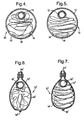
- the step of pushing the sub-assembly in the longitudinal direction X is continued ( Figure 2) until the airbag 14 is at least partially (and preferably fully) positioned inside the tubular housing 12 ( Figure 3).
- the structural member 16 provides support for the airbag 14 during installation of the airbag into the tubular housing 12. With this process, as shown in Figure 4, the airbag 14 has an irregular fold pattern when positioned inside the tubular housing 12.
- the airbag 14 may be folded into a predetermined regular pattern (as shown in Figure 5) either prior to pushing the sub-assembly of structural member 16 and airbag into the tubular housing 12, or whilst the sub-assembly is being pushed into position.
- a funnel-shaped member 22 or similar device may be positioned at the open end 20 of the tubular housing 12 to assist in the insertion of the sub-assembly of structural member 16 and airbag 14.
- the funnel-shaped member may be specially shaped to fold the airbag into the predetermined regular pattern during the insertion process. After assembly, the airbag 14 may be secured to the tubular housing 12 in any suitable manner.
- the tubular housing 12 may be moulded or extruded from plastics material.
- the tubular housing may be formed from fabric, shrink foil, or any other suitable material, which can be sewn or formed as a tubular housing.
- the tubular housing 12' is formed from fabric material which is joined along longitudinally extending edges 24' on the opposite side to the tear-line 18'.
- the tubular housing may contain separate shape maintaining elements (not shown).
- tubular housing 12 may be defined by a number of substantially axially aligned tubular members which either totally surround the sub-assembly of airbag 14 and structural member 16, or partially surround the sub-assembly along at least part of the length of the airbag.
- the structural member 16 is used for pushing the airbag 14 into the tubular housing 12. It will be appreciated that by using an alternative designed of structural member, the structural member could be used for pulling the airbag into the tubular housing.
- the present invention provides an airbag module 10,10' which is easy and cheap to assemble, and which has a minimal size.
Landscapes
- Engineering & Computer Science (AREA)
- Mechanical Engineering (AREA)
- Air Bags (AREA)
Description
- The present invention relates to a method of assembling an airbag module in which the airbag has an extended or longitudinally extending shape, and an airbag module assembled by such a method.
- Extended or longitudinally extending airbags are known, and are sometimes referred to as side curtains or side airbags. Such airbags can be mounted in the roof or door of a motor vehicle adjacent the side of an occupant seat, in general to provide protection for an occupant during a side impact on the vehicle. Assembly of such known airbag modules is both time-consuming and costly. US-A-5810390 describes a method and a module in accordance with the preamble of Claims 1 and 6.
- It is an object of the present invention to overcome the above mentioned disadvantages.
- A method of assembling an airbag module in accordance with the present invention comprises the steps of securing a longitudinally extending structural member inside an airbag having an extended profile to form a sub-assembly of the structural member and the airbag; drawing the sub-assembly through an open end of a longitudinally extending tubular housing; and continuing with the drawing step until the airbag is surrounded by the housing along at least part of the length of the airbag.
- The present invention also includes an airbag module comprising an airbag having an extended profile; a longitudinally extending structural member secured in positioned inside the airbag; and a longitudinally extending tubular housing having a longitudinally extending tear-line and surrounding the sub-assembly of structural member and airbag along at least part of the length of the airbag.
- The present invention provides a method of assembly with is easier and cheaper than previously known arrangements for airbag modules having an airbag with an extended profile; and also provides an airbag module which is minimal in size.
- The present invention will now be described, by way of example, with reference to the accompanying drawings, in which:-
- Figure 1 is a side view of a first step in the assembly of an airbag module in accordance with the present invention using a method in accordance with the present invention;
- Figure 2 is a side view of a second step in the assembly process of Figure 1;
- Figure 3 is a side view of a third step in the assembly process of Figure 1;
- Figure 4 is a cross-sectional view on the line IV-IV of Figure 3; and
- Figures 5 to 7 are cross-sectional views similar to that of Figure 4 of alternative embodiments of airbag module in accordance with the present invention.
-
- Referring to Figures 1 to 4, the
airbag module 10 in accordance with the present invention comprises a longitudinally extendingtubular housing 12; an airbag orcushion 14 having an extended profile; and a longitudinally extendingstructural member 16. Thestructural member 16 is positioned inside theairbag 14. Thestructural member 16 may be a gas lance or gas diffuser tube which is connected to an inflator (not shown) for the flow of inflation gas from the inflator into theairbag 14 during deployment of the airbag. In the latter case, the inflator may be secured to thestructural member 16 at the position where the structural member enters theairbag 14. Thetubular housing 12 has a longitudinally extending weakened section or tear-line 18 which splits during deployment of theairbag 14; and is open at oneend 20. - The method of assembling the
airbag module 10 in accordance with the present invention comprises securing thestructural member 16 inside theairbag 14 by any suitable method to form a sub-assembly; and then pushing the sub-assembly in the longitudinal direction X into thetubular housing 12 through theopen end 20 thereof, as shown in Figure 1. The step of pushing the sub-assembly in the longitudinal direction X is continued (Figure 2) until theairbag 14 is at least partially (and preferably fully) positioned inside the tubular housing 12 (Figure 3). Thestructural member 16 provides support for theairbag 14 during installation of the airbag into thetubular housing 12. With this process, as shown in Figure 4, theairbag 14 has an irregular fold pattern when positioned inside thetubular housing 12. In an alternative arrangement, theairbag 14 may be folded into a predetermined regular pattern (as shown in Figure 5) either prior to pushing the sub-assembly ofstructural member 16 and airbag into thetubular housing 12, or whilst the sub-assembly is being pushed into position. - A funnel-
shaped member 22 or similar device may be positioned at theopen end 20 of thetubular housing 12 to assist in the insertion of the sub-assembly ofstructural member 16 andairbag 14. The funnel-shaped member may be specially shaped to fold the airbag into the predetermined regular pattern during the insertion process. After assembly, theairbag 14 may be secured to thetubular housing 12 in any suitable manner. - The
tubular housing 12 may be moulded or extruded from plastics material. Alternatively, the tubular housing may be formed from fabric, shrink foil, or any other suitable material, which can be sewn or formed as a tubular housing. As shown in the alternative embodiments of airbag module 10' in Figures 6 and 7, where the airbag 14' has an irregular fold and a regular fold respectively, the tubular housing 12' is formed from fabric material which is joined along longitudinally extending edges 24' on the opposite side to the tear-line 18'. The tubular housing may contain separate shape maintaining elements (not shown). In a further alternative arrangement, thetubular housing 12 may be defined by a number of substantially axially aligned tubular members which either totally surround the sub-assembly ofairbag 14 andstructural member 16, or partially surround the sub-assembly along at least part of the length of the airbag. - In the above described process, the
structural member 16 is used for pushing theairbag 14 into thetubular housing 12. It will be appreciated that by using an alternative designed of structural member, the structural member could be used for pulling the airbag into the tubular housing. - The present invention provides an
airbag module 10,10' which is easy and cheap to assemble, and which has a minimal size.
Claims (12)
- A method of assembling an airbag module (10) comprising the steps of securing a longitudinally extending structural member (16) inside an airbag (14) having an extended profile to form a sub-assembly of the structural member and the airbag; characterized by drawing the sub-assembly through an open end (20) of a longitudinally extending tubular housing (12); and continuing with the drawing step until the airbag (14) is surrounded by the housing along at least part of the length of the airbag.
- A method as claimed in Claim 1, further comprising the step of folding the airbag (14) into a predetermined pattern either prior to, or during, the drawing step.
- A method as claimed in Claim 1 or Claim 2, wherein the drawing step comprises pushing the sub-assembly of the structural member (16) and the airbag (14) into the tubular housing (12) through the open end (20) thereof.
- A method as claimed in any one of Claims 1 to 3, further comprising placing a funnel shaped member (22) at the open end (20) of the tubular housing (12) prior to the drawing step.
- A method as claimed in Claim 2, further comprising placing a funnel shaped member (22) at the open end (20) of the tubular housing (12) prior to the drawing step, wherein the funnel shaped member is shaped to fold the airbag into the predetermined pattern during the drawing step.
- An airbag module (10) comprising an airbag (14) having an extended profile; and a longitudinally extending structural member (16) secured in position inside the airbag; characterized by a longitudinally extending tubular housing (12) having a longitudinally extending tear-line (18) and surrounding the sub-assembly of structural member and airbag along at least part of the length of the airbag.
- An airbag module as claimed in Claim 6, wherein the structural member (16) is a gas tube for delivering inflation gas to the airbag (14) during deployment of the airbag.
- An airbag module as claimed in Claim 6 or Claim 7, wherein the airbag (14) has an irregular fold pattern.
- An airbag module as claimed in any one of Claims 6 to 8, wherein the airbag (14) is secured to the tubular housing (12).
- An airbag module as claimed in any one of Claims 6 to 9, wherein the tubular housing (12) has been moulded or extruded from plastics material.
- An airbag module as claimed in any one of Claims 6 to 9, wherein the tubular housing (12) is formed from fabric material or shrink foil.
- An airbag module as claimed in any one of Claims 6 to 11, wherein the tubular housing (12) is defined by a number of tubular members which are substantially axially aligned.
Applications Claiming Priority (3)
| Application Number | Priority Date | Filing Date | Title |
|---|---|---|---|
| GB9910431A GB2349618B (en) | 1999-05-06 | 1999-05-06 | A method of assembling an airbag module |
| GB9910431 | 1999-05-06 | ||
| PCT/US2000/012273 WO2000068040A1 (en) | 1999-05-06 | 2000-05-04 | A method of assembling an airbag module |
Publications (2)
| Publication Number | Publication Date |
|---|---|
| EP1183169A1 EP1183169A1 (en) | 2002-03-06 |
| EP1183169B1 true EP1183169B1 (en) | 2004-08-11 |
Family
ID=10852887
Family Applications (1)
| Application Number | Title | Priority Date | Filing Date |
|---|---|---|---|
| EP00932090A Expired - Lifetime EP1183169B1 (en) | 1999-05-06 | 2000-05-04 | A method of assembling an airbag module |
Country Status (4)
| Country | Link |
|---|---|
| EP (1) | EP1183169B1 (en) |
| DE (1) | DE60012916T2 (en) |
| GB (1) | GB2349618B (en) |
| WO (1) | WO2000068040A1 (en) |
Families Citing this family (12)
| Publication number | Priority date | Publication date | Assignee | Title |
|---|---|---|---|---|
| DE10020677A1 (en) * | 2000-04-27 | 2001-10-31 | Delphi Tech Inc | Folding method and device |
| DE10056300A1 (en) * | 2000-11-14 | 2002-06-27 | Siemens Restraint Systems Gmbh | Airbag system for vehicles has pressurized gas supply that feeds gas into airbag via movable airbag connection in definable region of tubular housing on receiving trigger signal |
| US6808199B2 (en) * | 2002-04-09 | 2004-10-26 | Autoliv Asp, Inc. | Shrink wrap for inflatable curtain package |
| BRPI0412816A (en) | 2003-07-21 | 2006-09-26 | Siemens Energy & Automation | integral central plane balancing of a rotating fixture |
| US7083188B2 (en) | 2003-11-13 | 2006-08-01 | Autoliv Asp, Inc. | Tearable retention apparatus and method for an airbag cushion |
| JP4520504B2 (en) | 2004-11-15 | 2010-08-04 | タカタ・ペトリ アーゲー | Manufacturing method of gas bag package for airbag module |
| DE202005010864U1 (en) | 2004-11-15 | 2005-09-22 | Takata-Petri Ag | Airbag module for installation in motor vehicle has holding element and gas generator that are held on module housing by bayonet connection |
| GB2428408B (en) * | 2005-07-20 | 2007-06-20 | Nissan Technical Ct Europ Ltd | Vehicle airbag system |
| ATE543693T1 (en) | 2007-03-15 | 2012-02-15 | Takata Petri Ag | VEHICLE SEAT ARRANGEMENT AND METHOD FOR PROTECTING A VEHICLE OCCUPANT |
| DE102008012764B4 (en) * | 2008-03-05 | 2015-08-20 | Autoliv Development Ab | Door-side airbag module for motor vehicles |
| CN102099227B (en) | 2008-07-15 | 2014-04-16 | 高田-彼得里公开股份有限公司 | Vehicle seat arrangement and airbag arrangement for motor vehicle and method for protecting a vehicle occupant |
| CN104608733B (en) * | 2015-02-02 | 2017-01-11 | 上海东方久乐汽车安全气囊有限公司 | Curtain airbag wrapping cloth assembling device |
Citations (1)
| Publication number | Priority date | Publication date | Assignee | Title |
|---|---|---|---|---|
| US5810390A (en) * | 1996-12-09 | 1998-09-22 | Morton International, Inc. | Module case for side impact airbag module |
Family Cites Families (3)
| Publication number | Priority date | Publication date | Assignee | Title |
|---|---|---|---|---|
| JP3704844B2 (en) * | 1996-11-13 | 2005-10-12 | トヨタ自動車株式会社 | Arrangement structure of occupant protection device for automobile |
| JP3858325B2 (en) * | 1997-01-16 | 2006-12-13 | 豊田合成株式会社 | Side airbag device |
| JPH10203289A (en) * | 1997-01-24 | 1998-08-04 | Toyoda Gosei Co Ltd | Side airbag device |
-
1999
- 1999-05-06 GB GB9910431A patent/GB2349618B/en not_active Expired - Fee Related
-
2000
- 2000-05-04 DE DE60012916T patent/DE60012916T2/en not_active Expired - Lifetime
- 2000-05-04 EP EP00932090A patent/EP1183169B1/en not_active Expired - Lifetime
- 2000-05-04 WO PCT/US2000/012273 patent/WO2000068040A1/en not_active Ceased
Patent Citations (1)
| Publication number | Priority date | Publication date | Assignee | Title |
|---|---|---|---|---|
| US5810390A (en) * | 1996-12-09 | 1998-09-22 | Morton International, Inc. | Module case for side impact airbag module |
Also Published As
| Publication number | Publication date |
|---|---|
| WO2000068040A1 (en) | 2000-11-16 |
| EP1183169A1 (en) | 2002-03-06 |
| GB9910431D0 (en) | 1999-07-07 |
| DE60012916T2 (en) | 2004-12-23 |
| GB2349618B (en) | 2002-07-03 |
| DE60012916D1 (en) | 2004-09-16 |
| GB2349618A (en) | 2000-11-08 |
Similar Documents
| Publication | Publication Date | Title |
|---|---|---|
| EP0957007B1 (en) | Airbag for front passenger and folding method thereof | |
| EP1401687B1 (en) | A modular airbag inflator system | |
| US5730463A (en) | Air Bag Fold And Method | |
| EP1607277B1 (en) | Airbag apparatus for head-protecting | |
| US7185912B2 (en) | Knee protection airbag device | |
| KR101068648B1 (en) | Curtain airbags and vehicles | |
| EP0786383B1 (en) | Cover/director for air bag | |
| CN102219010B (en) | Safety airbag installation system | |
| EP2724901B1 (en) | Airbag device | |
| EP0787673B1 (en) | Folded air bag and air bag folding method | |
| US6808199B2 (en) | Shrink wrap for inflatable curtain package | |
| WO2000068040A1 (en) | A method of assembling an airbag module | |
| JP3338856B2 (en) | Gas bag for air bag module, method and apparatus for folding gas bag | |
| CN212500256U (en) | Airbag and combination system for a vehicle | |
| US20070001434A1 (en) | Air-bag | |
| CN102529869B (en) | The method of vehicle occupant restraint system and constraint Vehicular occupant | |
| US20150102588A1 (en) | Non-slitted tear seam for mini-wrappers | |
| JP2004210099A (en) | Curtain air bag and its assembly | |
| EP1212213B1 (en) | Airbag module | |
| EP1104724B1 (en) | Mounting arrangement for an airbag module | |
| CN101117112B (en) | Guide plate for side airbag | |
| KR101070147B1 (en) | Automotive Curtain Airbag Module | |
| JP3646593B2 (en) | Side airbag device | |
| US6938916B2 (en) | Vehicle with an airbag device connected to interior fittings | |
| US5785349A (en) | Elongated asymmetrical automotive airbag |
Legal Events
| Date | Code | Title | Description |
|---|---|---|---|
| PUAI | Public reference made under article 153(3) epc to a published international application that has entered the european phase |
Free format text: ORIGINAL CODE: 0009012 |
|
| 17P | Request for examination filed |
Effective date: 20011206 |
|
| AK | Designated contracting states |
Kind code of ref document: A1 Designated state(s): AT BE CH CY DE DK ES FI FR GB GR IE IT LI LU MC NL PT SE |
|
| RIN1 | Information on inventor provided before grant (corrected) |
Inventor name: ZIMMERBEUTEL, BERND, UWE Inventor name: GUTHKE, DETLEV, WILHELM Inventor name: NILSON, HANS, GERT |
|
| 17Q | First examination report despatched |
Effective date: 20030411 |
|
| GRAP | Despatch of communication of intention to grant a patent |
Free format text: ORIGINAL CODE: EPIDOSNIGR1 |
|
| GRAS | Grant fee paid |
Free format text: ORIGINAL CODE: EPIDOSNIGR3 |
|
| GRAA | (expected) grant |
Free format text: ORIGINAL CODE: 0009210 |
|
| AK | Designated contracting states |
Kind code of ref document: B1 Designated state(s): DE |
|
| REG | Reference to a national code |
Ref country code: IE Ref legal event code: FG4D |
|
| REF | Corresponds to: |
Ref document number: 60012916 Country of ref document: DE Date of ref document: 20040916 Kind code of ref document: P |
|
| PLBE | No opposition filed within time limit |
Free format text: ORIGINAL CODE: 0009261 |
|
| STAA | Information on the status of an ep patent application or granted ep patent |
Free format text: STATUS: NO OPPOSITION FILED WITHIN TIME LIMIT |
|
| 26N | No opposition filed |
Effective date: 20050512 |
|
| REG | Reference to a national code |
Ref country code: DE Ref legal event code: R081 Ref document number: 60012916 Country of ref document: DE Owner name: AUTOLIV DEVELOPMENT AB, SE Free format text: FORMER OWNER: DELPHI TECHNOLOGIES, INC., TROY, US Effective date: 20110415 Ref country code: DE Ref legal event code: R081 Ref document number: 60012916 Country of ref document: DE Owner name: AUTOLIV DEVELOPMENT AB, SE Free format text: FORMER OWNER: DELPHI TECHNOLOGIES, INC., TROY, MICH., US Effective date: 20110415 |
|
| REG | Reference to a national code |
Ref country code: DE Ref legal event code: R119 Ref document number: 60012916 Country of ref document: DE Effective date: 20121201 |
|
| PG25 | Lapsed in a contracting state [announced via postgrant information from national office to epo] |
Ref country code: DE Free format text: LAPSE BECAUSE OF NON-PAYMENT OF DUE FEES Effective date: 20121201 |
|
| PGFP | Annual fee paid to national office [announced via postgrant information from national office to epo] |
Ref country code: DE Payment date: 20110325 Year of fee payment: 12 |