EP1182838A2 - Multi-band DMT receiver - Google Patents
Multi-band DMT receiver Download PDFInfo
- Publication number
- EP1182838A2 EP1182838A2 EP01307114A EP01307114A EP1182838A2 EP 1182838 A2 EP1182838 A2 EP 1182838A2 EP 01307114 A EP01307114 A EP 01307114A EP 01307114 A EP01307114 A EP 01307114A EP 1182838 A2 EP1182838 A2 EP 1182838A2
- Authority
- EP
- European Patent Office
- Prior art keywords
- signal
- band
- demodulator
- discrete fourier
- fourier transform
- Prior art date
- Legal status (The legal status is an assumption and is not a legal conclusion. Google has not performed a legal analysis and makes no representation as to the accuracy of the status listed.)
- Granted
Links
- 238000000034 method Methods 0.000 claims abstract description 18
- 238000005070 sampling Methods 0.000 claims description 14
- 238000012545 processing Methods 0.000 claims description 9
- 238000001914 filtration Methods 0.000 claims description 6
- 230000003044 adaptive effect Effects 0.000 claims description 4
- 125000004122 cyclic group Chemical group 0.000 description 7
- 238000003780 insertion Methods 0.000 description 6
- 230000037431 insertion Effects 0.000 description 6
- 230000005540 biological transmission Effects 0.000 description 3
- 238000005516 engineering process Methods 0.000 description 3
- 238000007796 conventional method Methods 0.000 description 1
- 238000010586 diagram Methods 0.000 description 1
- 238000007493 shaping process Methods 0.000 description 1
- 238000011144 upstream manufacturing Methods 0.000 description 1
Images

Classifications
-
- H—ELECTRICITY
- H04—ELECTRIC COMMUNICATION TECHNIQUE
- H04L—TRANSMISSION OF DIGITAL INFORMATION, e.g. TELEGRAPHIC COMMUNICATION
- H04L27/00—Modulated-carrier systems
- H04L27/26—Systems using multi-frequency codes
- H04L27/2601—Multicarrier modulation systems
- H04L27/2647—Arrangements specific to the receiver only
- H04L27/2649—Demodulators
- H04L27/2653—Demodulators with direct demodulation of individual subcarriers
-
- H—ELECTRICITY
- H04—ELECTRIC COMMUNICATION TECHNIQUE
- H04L—TRANSMISSION OF DIGITAL INFORMATION, e.g. TELEGRAPHIC COMMUNICATION
- H04L27/00—Modulated-carrier systems
- H04L27/26—Systems using multi-frequency codes
- H04L27/2601—Multicarrier modulation systems
- H04L27/2647—Arrangements specific to the receiver only
- H04L27/2649—Demodulators
- H04L27/265—Fourier transform demodulators, e.g. fast Fourier transform [FFT] or discrete Fourier transform [DFT] demodulators
- H04L27/2651—Modification of fast Fourier transform [FFT] or discrete Fourier transform [DFT] demodulators for performance improvement
Definitions
- the present invention relates to the demodulation of a multi-band DMT signal in a receiver, and particularly but not exclusively to the demodulation of a multi-band DMT signal in the transceiver of a modem.
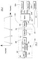
- FIG. 1 there is shown an example of a multi-band signal transmitted in the upstream (or uplink) of a communications system.
- the multi-band signal comprises two bands.
- a first band is defined between the frequencies f 1 and f 2
- a second band is defined between the frequencies f 3 and f 4 .
- a downstream frequency band may be provided between the frequencies f 2 and f 3
- a further downstream frequency band may be provided beyond the frequency f 4 .
- the processing speed of the receiver is determined by the highest frequency of the multi-band signal. That is, the receiver has to operate at a speed such that the received signals having the highest frequencies can be processed within system constraints.
- a receiver for receiving a multi-band signal modulated using an inverse discrete Fourier transform comprising: a plurality of demodulators, each demodulator for demodulating a respective one of the plurality of bands in a multi-band signal wherein each demodulator includes a discrete Fourier transform.
- each demodulator includes a discrete Fourier transform.
- the process speed of each demodulator may then be determined by the respective frequency band. That is, if a particular demodulator processes a frequency band having a high frequency, then a corresponding high sampling speed is required in the respective demodulator. A lower frequency band requires a lower sampling speed in the respective demodulator.
- the process speed of each demodulator is preferably determined by the respective frequency band of the signal processed therein.
- the multi-band signal may be generated by nulling selected tones in the modulator.
- the multi-band signal may be generated by filtering the output of the modulator.
- each demodulator may further include an echo canceller for removing an echo associated with the signal in a transmitter of the transceiver from the received signal.
- the echo canceller may be connected to remove the echo at the inputs of the discrete Fourier transform.
- Each echo canceller may comprise an adaptive filter.
- the present invention provides a method of demodulating a multi-band signal modulated using an inverse discrete Fourier transform, comprising the step of: providing a demodulator for each respective band in a multi-band signal, wherein each demodulator performs .a discrete Fourier transform.
- Each demodulator may further comprise an equalisation step.
- Each demodulator may further filter the received signal prior to the discrete Fourier transform.
- the multi-band signal may be generated by nulling selected tones in the modulator.
- the multi-band signal may be generated by filtering the output of the modulator.
- the demodulating step may be carried out in a transceiver.
- each demodulator further performs an echo cancellation step to remove an echo associated with a signal in a transmitter of the transceiver from the received signal.
- a modem transceiver transmits a DMT (discrete multi-tone) signal, and the DMT signal is received by a transceiver of another modem.
- DMT discrete multi-tone
- first modem 214 transmits a multi-band signal to the second modem 218. Therefore only the transmitter portion of a transceiver of the first modem 214 is discussed in detail and only a receiver portion of the transceiver of the second modem 218 is discussed in detail.
- the transmitter of the first modem 214 includes an inverse discrete Fourier transform 204, a digital to analogue converter 218, and a hybrid 212.
- a DMT transmitter As the transmitter described herein is a DMT transmitter, there is also provided a cyclic prefix (CP) insertion block 205.
- the inverse discrete Fourier transform (IDFT) block 204 receives on a plurality of signal lines 202 data to be encoded for transmission. The thus encoded data is output by the IDFT block 204 in series on line 207.
- the operation of the IDFT block 204 is outside the scope of the present invention, and its implementation will be well know to one skilled in the art.
- the CP insertion block inserts a 32 sample guard band in front of the 512 sample symbols generated by the IDFT. As known in the art, the CP insertion includes repeating the last 32 sample of the 512 sample symbol to thereby generate a 544 sample symbol.
- Modulated and encoded data output by the CP insertion block 205 on line 206 is converted into an analogue signal on line 210 by the digital to analogue converter 208, and the hybrid 212 transmits the analogue signal on a channel 216.
- the plurality of signals on line 202 are provided by a transmitter which generates a discrete multi-tone (DMT) signal with N/2 tones with a tone spacing of ⁇ F. Consequently the IDFT generates a transform having N points.
- the bands of the multi-band signal are generated by nulling certain tones at the input to the IDFT204. In addition, the nulling may be assisted by appropriate filters at the output of the IDFT 204.
- the symbols may be optionally windowed. Windowing shapes the symbols before transmission in order to reduce the leakage in the adjacent band. Windowing multiplies a certain number of samples at the beginning and end of a symbol by a weighting function. Usually the number of windowed samples is smaller than the length of the guard-band. The shaping of two contiguous symbols could overlap. This windowing principle is used, for example, in the VDSL multi-carrier standard.
- the analogue signal on a channel 216 is received by the transceiver of the modem 218.
- the transceiver of the modem 218 includes a hybrid 220 and a splitter 221.
- the receiver of the modem 218 in addition comprises a plurality, in this example two, of receivers 224a and 224b.
- the signal transmitted by the transmitter of the first modem 214 corresponds to the signal of Figure 1 and includes two frequency bands.
- the signal will include a plurality n of frequency bands, and the receiver of the modem 218 will be provided with a plurality n of the receivers 224.
- the modem 218 includes transmitter circuitry 223 which provides a signal to be transmitted to the hybrid 220 on line 225.
- Each of the demodulators 224a and 224b is constructed identically, and the various components therein have identical reference numerals except for the designation of a or b.
- the receiver 224a will be described hereinafter, and it will be understood that demodulator 224b is constructed in exactly the same manner.
- the signal on line 222 is converted into an analogue signal on line 316 by an analogue to digital converter 300, and then presented to respective low and high pass filters 302a and 302b.
- the output of the low pass filter 302a on line 314a is processed by block 304, which in turn generates a signal to the first receiver 224a.
- the block 304 is a downsampler.
- the principle of this device is to reduce the sampling speed by a certain factor. For example a downsampler by 2 divides the sampling speed by 2 between its input and output. The division is done by taking one sample every two samples. For the input sequence 1 2 3 4 5 6 7 8 9 10 ... to the downsampler, the output sequence is 1 3 5 7 9 11 ...
- the output of the high pass filter 302b on line 314b forms the signal on line 223b to the second receiver.
- the signal on line 222 is provided to respective low and high pass filters 310a and 310b.
- the outputs of these filters on lines 315a and 316b are converted into digital form by analogue to digital converters 312a and 312b, which generate the signals 223a and 223b to the receivers 224a and 224b.
- both streams are sampled at their respective Nyquist frequency even if the ADC is running at the Nyquist frequency of the highest band.
- Each filter stream in the digital implementation of Figure 3(a), and each stream in the analogue implementation of Figure 3(b), can be processed with a DFT of Fs,k/ ⁇ F points. This is because each stream need only process the points for its particular band.
- Each stream is sampled at a frequency Fs,k, where Fs,k is at least two times the maximum frequency of the band.
- the receiver 224a comprises a time equaliser 234a, a subtractor 238a, a cyclic prefix removal block 239a, a discrete Fourier transform (FFT) 244a, a frequency equaliser 248a, and an echo canceller 242a.
- the echo canceller 242a is comprised of an adaptive filter.
- the time equaliser 234a is preferably a finite impulse response (FIR) filter.
- the echo canceller 242a preferably comprises an adaptive filter and receives a representation on line 225 of the signal in the transceiver for the modem 218 which is being transmitted by the hybrid 220.
- the echo canceller 242a then provides an estimate of the echo associated with this transmitted signal on line 262a.
- the subtractor 238a subtracts the estimate of the echo on line 262a from the time equalised received signal on line 236a, to generate an estimate of the received signal on line 240a.
- the signal on line 240a is used to control the echo canceller 242a to adjust the estimate of the echo on line 262a.
- the cyclic prefix (CP) removal block 239a operates in the reverse manner to the cyclic prefix (CP) insertion block 205 to remove the 32 samples of the cyclic prefix, forming a guard band, from the 544 samples of the received symbol.
- CP cyclic prefix
- the estimate of the received signal on line 241a, after the cyclic prefix removal block, is then input to the discrete Fourier transform 244a.
- the outputs of the discrete Fourier transform on line 246a are provided to the frequency equaliser 248a for equalisation.
- the thus equalised signals provided on line 250a are provided for further processing in the receiver of the modem 218.
- the CP removal block 239a, the discrete Fourier transform 244a and the equaliser 248a each receive a clocked signal on line 264a for controlling the speed of the operations performed therein.
- the receiver 224b is similarly constructed.
- the main advantage of the invention is that the processing of the lower band, or bands, can be performed at a lower speed. Primarily this means that the time equaliser 234 and the echo canceller 242 consume less CPU processing.
- Each of the filters 302 or 310 implement the necessary processing to select the frequency band for the respective receiver.
Landscapes
- Physics & Mathematics (AREA)
- Discrete Mathematics (AREA)
- General Physics & Mathematics (AREA)
- Mathematical Physics (AREA)
- Engineering & Computer Science (AREA)
- Computer Networks & Wireless Communication (AREA)
- Signal Processing (AREA)
- Telephonic Communication Services (AREA)
- Cable Transmission Systems, Equalization Of Radio And Reduction Of Echo (AREA)
- Mobile Radio Communication Systems (AREA)
Abstract
Description
Claims (24)
- A receiver for demodulating a multi-tone multi-band signal modulated using an inverse discrete Fourier transform to have a plurality of tones spaced in frequency in a plurality of frequency bands, the receiver comprising:a plurality of demodulators for demodulating respective frequency bands of the multi-tone, multi-band signal, each demodulator including a discrete Fourier transform for carrying out a discrete Fourier transform on the plurality of tones within the respective frequency band.
- A receiver according to claim 1 further comprising a splitter for dividing the received multi-tone multi-band signal into a plurality of streams of respective frequency bands on respective splitter outputs, the respective splitter outputs being connected to respective demodulators to supply the individual streams to the respective demodulators according to the frequency band of the stream.
- A receiver according to claim 1 or 2 wherein the respective discrete Fourier transforms in the respective demodulators are carried out at respective sampling frequencies (Fs,k) where the sampling frequency varies between demodulators in accordance with the respective frequency band of the demodulator.
- A receiver according to claim 3 wherein the sampling frequency Fs,k used in each demodulator is at least double the maximum frequency in the respective frequency band.
- The receiver of any preceding claim wherein the process speed of each demodulator is determined by the respective frequency band.
- The receiver of any preceding claim wherein each demodulator further includes an equaliser connected to the output of the discrete Fourier transform.
- The receiver of any preceding claim wherein each demodulator further includes a filter for filtering the received signal prior to the discrete Fourier transform.
- A transceiver including a receiver according to any preceding claim and a transmitter.
- The transceiver of claim 8 in which each demodulator includes an echo canceller for removing an echo associated with a signal in the transmitter from the received signal.
- The transceiver of claim 9 in which the echo canceller is connected to remove the echo at the input to the discrete Fourier transform.
- The transceiver of claim 9 or claim 10 in which each echo canceller comprises an adaptive filter and is connected to the transmitter to receive a representation of the signal transmitted by the transmitter.
- A system comprising:a transmitter having a modulator for generating a multi-tone signal having a plurality of tones using an inverse discrete Fourier transform, the multi-tone signal having a plurality of frequency bands; anda receiver according to any of claims 1 to 7.
- The system of claim 12 in which the multi-band signal is generated by nulling selected tones in the modulator.
- The receiver of claim 12 or 13 in which the multi-band signal is generated by filtering the output of the modulator.
- A method of demodulating a multi-tone multi-band signal modulated using an inverse discrete Fourier transform, comprising the steps of:splitting the multi-band signal into a plurality of different frequency bands; anddemodulating each of the plurality of frequency bands with a respective demodulator using a discrete Fourier transform.
- A method of demodulating a multi-band signal modulated using an inverse discrete Fourier transform comprising the step of:demodulating each respective band of the multi-band signal with a demodulator wherein each demodulator performs a discrete Fourier transform.
- The method of claim 15 or 16 further comprising equalising the signal in each demodulator.
- The method of claim 15, 16 or 17 wherein each demodulator filters the received signal prior to the discrete Fourier transform.
- The method of any one of claims 15 to 18 in which the demodulating step is carried out in a transceiver.
- The method of claim 19 in which each demodulator further performs an echo cancellation step to remove an echo associated with the signal in a transmitter of the transceiver from the received signal.
- The method of any one of claims 15 to 20 in which the multi-band signal is generated by nulling selected tones in the modulator.
- The method of any one of claims 15 to 21 in which the multi-band signal is generated by filtering the output of the modulator.
- A receiver for receiving a multi-tone signal having a plurality of frequency bands, the signal within each frequency band having a plurality of spaced tones, the receiver comprising:wherein the respective streams are supplied to respective demodulators.a plurality of demodulators each including a discrete Fourier transform for demodulating a respective one of the plurality of frequency bands in the signal received, anda splitter for dividing the received multi-band multi-tone signal into a plurality of streams, each stream being of a respective frequency band;
- A receiver according to claim 2, 3, 4 or 23 further comprising:at least one downsampler between the splitter and at least one of the demodulators operating on a lower frequency band but not between the splitter and the demodulator or demodulators operating on a higher frequency band or bands than the lower frequency band,the or each downsampler reducing the sampling speed of the lower frequency band stream before processing by the respective demodulator.
Applications Claiming Priority (2)
| Application Number | Priority Date | Filing Date | Title |
|---|---|---|---|
| GB0020624 | 2000-08-21 | ||
| GBGB0020624.3A GB0020624D0 (en) | 2000-08-21 | 2000-08-21 | Multi band DMT receiver |
Publications (3)
| Publication Number | Publication Date |
|---|---|
| EP1182838A2 true EP1182838A2 (en) | 2002-02-27 |
| EP1182838A3 EP1182838A3 (en) | 2003-10-29 |
| EP1182838B1 EP1182838B1 (en) | 2006-11-15 |
Family
ID=9898048
Family Applications (1)
| Application Number | Title | Priority Date | Filing Date |
|---|---|---|---|
| EP01307114A Expired - Lifetime EP1182838B1 (en) | 2000-08-21 | 2001-08-21 | Multi-band DMT receiver |
Country Status (4)
| Country | Link |
|---|---|
| US (2) | US7406141B1 (en) |
| EP (1) | EP1182838B1 (en) |
| DE (1) | DE60124467T2 (en) |
| GB (1) | GB0020624D0 (en) |
Families Citing this family (3)
| Publication number | Priority date | Publication date | Assignee | Title |
|---|---|---|---|---|
| GB0020624D0 (en) * | 2000-08-21 | 2000-10-11 | Element 14 Inc | Multi band DMT receiver |
| US7796544B2 (en) * | 2002-06-07 | 2010-09-14 | Tokyo Electron Limited | Method and system for providing an analog front end for multiline transmission in communication systems |
| JP6226945B2 (en) * | 2015-12-11 | 2017-11-08 | アンリツ株式会社 | Multiband equalizer, error rate measurement system using the same, error rate measurement device, and path selection method |
Family Cites Families (25)
| Publication number | Priority date | Publication date | Assignee | Title |
|---|---|---|---|---|
| JP3183685B2 (en) * | 1991-09-13 | 2001-07-09 | 富士通株式会社 | Optical communication system |
| SE9203384L (en) * | 1992-11-13 | 1993-10-25 | Televerket | Method and apparatus for dynamic allocation of multiple carrier channels for multiple access through frequency multiplexing |
| US5317596A (en) * | 1992-12-01 | 1994-05-31 | The Board Of Trustees Of The Leland Stanford, Junior University | Method and apparatus for echo cancellation with discrete multitone modulation |
| US5365470A (en) * | 1993-02-10 | 1994-11-15 | Trw Inc. | Fast fourier transform multiplexed pipeline |
| JPH0723070A (en) | 1993-06-15 | 1995-01-24 | Fujitsu Ltd | Demodulator for multi-carrier modulation signal |
| US5930231A (en) * | 1995-06-30 | 1999-07-27 | Scientific-Atlanta, Inc. | Block spectrum receiver for a broadband communications system |
| GB2304504A (en) | 1995-08-19 | 1997-03-19 | Northern Telecom Ltd | OFDM receiver includes digital filter |
| AU6853996A (en) | 1995-08-31 | 1997-03-19 | Usa Digital Radio Partners L.P. | Am compatible digital waveform demodulation using a dual fft |
| DE19612108A1 (en) * | 1996-03-27 | 1997-10-02 | Bosch Gmbh Robert | Point-to-multipoint radio transmission system |
| US6055268A (en) * | 1996-05-09 | 2000-04-25 | Texas Instruments Incorporated | Multimode digital modem |
| US5949796A (en) * | 1996-06-19 | 1999-09-07 | Kumar; Derek D. | In-band on-channel digital broadcasting method and system |
| CA2184541A1 (en) * | 1996-08-30 | 1998-03-01 | Tet Hin Yeap | Method and apparatus for wavelet modulation of signals for transmission and/or storage |
| US6128276A (en) * | 1997-02-24 | 2000-10-03 | Radix Wireless, Inc. | Stacked-carrier discrete multiple tone communication technology and combinations with code nulling, interference cancellation, retrodirective communication and adaptive antenna arrays |
| US6148024A (en) | 1997-03-04 | 2000-11-14 | At&T Corporation | FFT-based multitone DPSK modem |
| US5818296A (en) | 1997-06-17 | 1998-10-06 | Hughes Electronics Corporation | FSK demodulator using goertzel's discrete fourier transform |
| US6442195B1 (en) * | 1997-06-30 | 2002-08-27 | Integrated Telecom Express, Inc. | Multiple low speed sigma-delta analog front ends for full implementation of high-speed data link protocol |
| EP0912023A1 (en) | 1997-10-27 | 1999-04-28 | Alcatel | Demodulation and equalisation of multicarrier signals |
| EP0969637A1 (en) | 1998-06-29 | 2000-01-05 | Alcatel | Equalisation in multicarrier receivers |
| EP0967763B1 (en) | 1998-06-29 | 2004-12-01 | Alcatel | Multicarrier receiver with per-carrier RLS frequency domain equalisation |
| US6496546B1 (en) * | 1998-07-15 | 2002-12-17 | Lucent Technologies Inc. | Software-defined transceiver for a wireless telecommunications system |
| US6470055B1 (en) * | 1998-08-10 | 2002-10-22 | Kamilo Feher | Spectrally efficient FQPSK, FGMSK, and FQAM for enhanced performance CDMA, TDMA, GSM, OFDN, and other systems |
| CA2299821C (en) * | 1999-03-04 | 2004-08-10 | Nippon Telegraph And Telephone Corporation | Variable transmission rate digital modem with multi-rate filter bank |
| JP2001069046A (en) * | 1999-08-30 | 2001-03-16 | Fujitsu Ltd | Transmission / reception system and reception device |
| US6449246B1 (en) * | 1999-09-15 | 2002-09-10 | Telcordia Technologies, Inc. | Multicarrier personal access communication system |
| GB0020624D0 (en) * | 2000-08-21 | 2000-10-11 | Element 14 Inc | Multi band DMT receiver |
-
2000
- 2000-08-21 GB GBGB0020624.3A patent/GB0020624D0/en not_active Ceased
- 2000-10-10 US US09/686,784 patent/US7406141B1/en not_active Expired - Fee Related
-
2001
- 2001-08-21 DE DE60124467T patent/DE60124467T2/en not_active Expired - Lifetime
- 2001-08-21 EP EP01307114A patent/EP1182838B1/en not_active Expired - Lifetime
-
2008
- 2008-07-22 US US12/177,800 patent/US7583742B2/en not_active Expired - Fee Related
Also Published As
| Publication number | Publication date |
|---|---|
| GB0020624D0 (en) | 2000-10-11 |
| DE60124467D1 (en) | 2006-12-28 |
| US7583742B2 (en) | 2009-09-01 |
| US20080279309A1 (en) | 2008-11-13 |
| US7406141B1 (en) | 2008-07-29 |
| EP1182838B1 (en) | 2006-11-15 |
| EP1182838A3 (en) | 2003-10-29 |
| DE60124467T2 (en) | 2007-09-13 |
Similar Documents
| Publication | Publication Date | Title |
|---|---|---|
| EP2315386B1 (en) | OFDM communications methods and apparatus | |
| EP0929172B1 (en) | Multicarrier modulation system, with variable symbol rates | |
| JP4410801B2 (en) | Modulation and demodulation of OFDM signal | |
| US7039000B2 (en) | Timing synchronization for OFDM-based wireless networks | |
| CN100448184C (en) | Receiver for Orthogonal Frequency Division Multiplexing System | |
| CN101119355A (en) | Sending equipment, receiving equipment and radio communication systems | |
| JP2002543673A (en) | Window function for maintaining orthogonality of channels in receiving OFDM symbols | |
| CN101926142A (en) | Method and apparatus for eliminating additive sinusoidal interference in OFDM receivers | |
| EP1005203A1 (en) | Multistandard DMT DSL transmission system | |
| US7583742B2 (en) | Multi-band DMT receiver | |
| KR100605109B1 (en) | Method and Device for Optimizing Signal-to-Noise Ratio Using Oversampling in Orthogonal Frequency Division Multiplexing System | |
| US7463678B2 (en) | Equalization scheme for DSL receivers in presence of an under-sampled or over-sampled transmit IDFT | |
| JP2001313594A (en) | DMT system time domain equalizer coefficient updating method, receiving method, DMT system and DMT modem | |
| CN106413006A (en) | OFDM communication method and system with uniform subband overlapping | |
| KR100440833B1 (en) | Digital receiver for a signal generated with discrete multi-tone modulation | |
| JP4345194B2 (en) | Demodulator | |
| CN100417052C (en) | Orthogonal frequency division multiplexing transmitter and method for processing orthogonal frequency division multiplexing signals | |
| WO2003079594A1 (en) | Equalization scheme for dsl receivers in presence of an under-sampled or over-sampled transmit idft | |
| EP1014638A1 (en) | Synchronisation techniques for OFDM communications systems | |
| HK1157092B (en) | Ofdm communications methods and apparatus | |
| EP1434363A1 (en) | Efficient echo canceller and method |
Legal Events
| Date | Code | Title | Description |
|---|---|---|---|
| PUAI | Public reference made under article 153(3) epc to a published international application that has entered the european phase |
Free format text: ORIGINAL CODE: 0009012 |
|
| AK | Designated contracting states |
Kind code of ref document: A2 Designated state(s): AT BE CH CY DE DK ES FI FR GB GR IE IT LI LU MC NL PT SE TR |
|
| AX | Request for extension of the european patent |
Free format text: AL;LT;LV;MK;RO;SI |
|
| PUAL | Search report despatched |
Free format text: ORIGINAL CODE: 0009013 |
|
| AK | Designated contracting states |
Kind code of ref document: A3 Designated state(s): AT BE CH CY DE DK ES FI FR GB GR IE IT LI LU MC NL PT SE TR |
|
| AX | Request for extension of the european patent |
Extension state: AL LT LV MK RO SI |
|
| 17P | Request for examination filed |
Effective date: 20040429 |
|
| AKX | Designation fees paid |
Designated state(s): DE FR GB |
|
| GRAP | Despatch of communication of intention to grant a patent |
Free format text: ORIGINAL CODE: EPIDOSNIGR1 |
|
| RAP1 | Party data changed (applicant data changed or rights of an application transferred) |
Owner name: BROADCOM CORPORATION |
|
| GRAS | Grant fee paid |
Free format text: ORIGINAL CODE: EPIDOSNIGR3 |
|
| GRAA | (expected) grant |
Free format text: ORIGINAL CODE: 0009210 |
|
| AK | Designated contracting states |
Kind code of ref document: B1 Designated state(s): DE FR GB |
|
| REG | Reference to a national code |
Ref country code: GB Ref legal event code: FG4D |
|
| REF | Corresponds to: |
Ref document number: 60124467 Country of ref document: DE Date of ref document: 20061228 Kind code of ref document: P |
|
| RAP2 | Party data changed (patent owner data changed or rights of a patent transferred) |
Owner name: BROADCOM CORPORATION |
|
| ET | Fr: translation filed | ||
| PLBE | No opposition filed within time limit |
Free format text: ORIGINAL CODE: 0009261 |
|
| STAA | Information on the status of an ep patent application or granted ep patent |
Free format text: STATUS: NO OPPOSITION FILED WITHIN TIME LIMIT |
|
| 26N | No opposition filed |
Effective date: 20070817 |
|
| REG | Reference to a national code |
Ref country code: FR Ref legal event code: CA |
|
| PGFP | Annual fee paid to national office [announced via postgrant information from national office to epo] |
Ref country code: GB Payment date: 20130823 Year of fee payment: 13 Ref country code: FR Payment date: 20130820 Year of fee payment: 13 |
|
| GBPC | Gb: european patent ceased through non-payment of renewal fee |
Effective date: 20140821 |
|
| REG | Reference to a national code |
Ref country code: FR Ref legal event code: ST Effective date: 20150430 |
|
| PG25 | Lapsed in a contracting state [announced via postgrant information from national office to epo] |
Ref country code: GB Free format text: LAPSE BECAUSE OF NON-PAYMENT OF DUE FEES Effective date: 20140821 |
|
| PG25 | Lapsed in a contracting state [announced via postgrant information from national office to epo] |
Ref country code: FR Free format text: LAPSE BECAUSE OF NON-PAYMENT OF DUE FEES Effective date: 20140901 |
|
| REG | Reference to a national code |
Ref country code: DE Ref legal event code: R082 Ref document number: 60124467 Country of ref document: DE Representative=s name: BOSCH JEHLE PATENTANWALTSGESELLSCHAFT MBH, DE Ref country code: DE Ref legal event code: R081 Ref document number: 60124467 Country of ref document: DE Owner name: AVAGO TECHNOLOGIES INTERNATIONAL SALES PTE. LT, SG Free format text: FORMER OWNER: BROADCOM CORP., IRVINE, CALIF., US Ref country code: DE Ref legal event code: R081 Ref document number: 60124467 Country of ref document: DE Owner name: AVAGO TECHNOLOGIES GENERAL IP (SINGAPORE) PTE., SG Free format text: FORMER OWNER: BROADCOM CORP., IRVINE, CALIF., US |
|
| REG | Reference to a national code |
Ref country code: DE Ref legal event code: R082 Ref document number: 60124467 Country of ref document: DE Representative=s name: BOSCH JEHLE PATENTANWALTSGESELLSCHAFT MBH, DE Ref country code: DE Ref legal event code: R081 Ref document number: 60124467 Country of ref document: DE Owner name: AVAGO TECHNOLOGIES INTERNATIONAL SALES PTE. LT, SG Free format text: FORMER OWNER: AVAGO TECHNOLOGIES GENERAL IP (SINGAPORE) PTE. LTD., SINGAPORE, SG |
|
| PGFP | Annual fee paid to national office [announced via postgrant information from national office to epo] |
Ref country code: DE Payment date: 20190831 Year of fee payment: 19 |
|
| REG | Reference to a national code |
Ref country code: DE Ref legal event code: R119 Ref document number: 60124467 Country of ref document: DE |
|
| PG25 | Lapsed in a contracting state [announced via postgrant information from national office to epo] |
Ref country code: DE Free format text: LAPSE BECAUSE OF NON-PAYMENT OF DUE FEES Effective date: 20210302 |