EP1182763A1 - Cell protective circuit - Google Patents
Cell protective circuit Download PDFInfo
- Publication number
- EP1182763A1 EP1182763A1 EP00962999A EP00962999A EP1182763A1 EP 1182763 A1 EP1182763 A1 EP 1182763A1 EP 00962999 A EP00962999 A EP 00962999A EP 00962999 A EP00962999 A EP 00962999A EP 1182763 A1 EP1182763 A1 EP 1182763A1
- Authority
- EP
- European Patent Office
- Prior art keywords
- battery
- current
- value
- current value
- region
- Prior art date
- Legal status (The legal status is an assumption and is not a legal conclusion. Google has not performed a legal analysis and makes no representation as to the accuracy of the status listed.)
- Withdrawn
Links
Images





Classifications
-
- H—ELECTRICITY
- H02—GENERATION; CONVERSION OR DISTRIBUTION OF ELECTRIC POWER
- H02H—EMERGENCY PROTECTIVE CIRCUIT ARRANGEMENTS
- H02H7/00—Emergency protective circuit arrangements specially adapted for specific types of electric machines or apparatus or for sectionalised protection of cable or line systems, and effecting automatic switching in the event of an undesired change from normal working conditions
- H02H7/18—Emergency protective circuit arrangements specially adapted for specific types of electric machines or apparatus or for sectionalised protection of cable or line systems, and effecting automatic switching in the event of an undesired change from normal working conditions for batteries; for accumulators
-
- H—ELECTRICITY
- H01—ELECTRIC ELEMENTS
- H01M—PROCESSES OR MEANS, e.g. BATTERIES, FOR THE DIRECT CONVERSION OF CHEMICAL ENERGY INTO ELECTRICAL ENERGY
- H01M10/00—Secondary cells; Manufacture thereof
- H01M10/42—Methods or arrangements for servicing or maintenance of secondary cells or secondary half-cells
- H01M10/425—Structural combination with electronic components, e.g. electronic circuits integrated to the outside of the casing
-
- H—ELECTRICITY
- H02—GENERATION; CONVERSION OR DISTRIBUTION OF ELECTRIC POWER
- H02J—ELECTRIC POWER NETWORKS; CIRCUIT ARRANGEMENTS OR SYSTEMS FOR SUPPLYING OR DISTRIBUTING ELECTRIC POWER; SYSTEMS FOR STORING ELECTRIC ENERGY
- H02J7/00—Circuit arrangements for charging or discharging batteries or for supplying loads from batteries
- H02J7/90—Regulation of charging or discharging current or voltage
- H02J7/971—Regulation of charging or discharging current or voltage the charge cycle being controlled or terminated in response to non-electric parameters
- H02J7/975—Regulation of charging or discharging current or voltage the charge cycle being controlled or terminated in response to non-electric parameters in response to temperature
-
- Y—GENERAL TAGGING OF NEW TECHNOLOGICAL DEVELOPMENTS; GENERAL TAGGING OF CROSS-SECTIONAL TECHNOLOGIES SPANNING OVER SEVERAL SECTIONS OF THE IPC; TECHNICAL SUBJECTS COVERED BY FORMER USPC CROSS-REFERENCE ART COLLECTIONS [XRACs] AND DIGESTS
- Y02—TECHNOLOGIES OR APPLICATIONS FOR MITIGATION OR ADAPTATION AGAINST CLIMATE CHANGE
- Y02E—REDUCTION OF GREENHOUSE GAS [GHG] EMISSIONS, RELATED TO ENERGY GENERATION, TRANSMISSION OR DISTRIBUTION
- Y02E60/00—Enabling technologies; Technologies with a potential or indirect contribution to GHG emissions mitigation
- Y02E60/10—Energy storage using batteries
Definitions
- the present invention relates to a battery protective circuit, and more particularly to a configuration for preventing a value of current flowing in a battery from exceeding a guaranteed current when a short or overcharge occurs.
- personal digital assistants such as a portable telephone, a notebook-sized personal computer and a video camera are widely used. These personal digital assistants use a battery for supplying power. A rechargeable secondary battery is used for such a battery.
- the battery protective circuit includes a PTC (Positive Temperature Coefficient) element and a thermal protector.
- the PTC element or the thermal protector serves as a current and temperature detecting circuit, operating in such a manner that electric resistance thereof increases as a larger current flows in the element and temperature becomes higher, and electric resistance thereof increases rapidly to suppress current when a certain temperature is reached. Further, a thermistor has its resistance value changed as an ambient temperature rises.
- the conventional battery protective circuit has a problem as described below. Referring to Fig. 12, the problem of the conventional battery protective circuit will be described.
- the ordinate and the abscissa respectively represent voltage and current.
- A represents a charge-guaranteed region in which a battery is rechargeable
- BZ represents a protection region in which a current and temperature detecting circuit such as a PTC element or a thermal protector is functional.
- the charge-guaranteed region A represents a relation between current flowing in the battery and voltage across terminals of the battery.
- the protection region BZ represents a relation between current flowing in the PTC element or the like (and the battery) and voltage across terminals of the PTC element or the like.
- the charge-guaranteed region A is a region in which the battery can protect itself, and the protection region BZ is a region in which the current and temperature detecting circuit is functional.
- the conventional battery protective circuit has performed its protecting function when heavy current flows, regardless of the charge-guaranteed region A, as shown in Fig. 12.
- the present invention is made to solve the above mentioned problem, and its object is to provide a battery protective circuit which can ensure the safety and reliability of a rechargeable battery and a device operated by the battery.
- the present invention provides a battery protective circuit for a rechargeable battery, including a current-amount control circuit including a current and temperature detecting circuit provided near the battery, operative to detect a value of current flowing in the battery and an ambient temperature, and to decrease the current value when the current value and the ambient temperature reach a value of a protection region, wherein the minimum current value in the protection region is less than the maximum current value in the charge-guaranteed region in which the battery is rechargeable, and the maximum current value in the protection region is greater than the maximum current value in the charge-guaranteed region.
- the present invention provides a battery protective circuit for a rechargeable battery, including: a current-amount control circuit including a current and temperature detecting circuit provided near the battery, operative to detect a value of current flowing in the battery and an ambient temperature, and to decrease the current value when the current value and the ambient temperature reach a value of a first protection region; and an interconnection layer supplying current to be flown in the battery, including a meltable portion to be melted and cut off when the value of current flowing in the battery reaches a value of a second protection region.
- a current-amount control circuit including a current and temperature detecting circuit provided near the battery, operative to detect a value of current flowing in the battery and an ambient temperature, and to decrease the current value when the current value and the ambient temperature reach a value of a first protection region
- an interconnection layer supplying current to be flown in the battery, including a meltable portion to be melted and cut off when the value of current flowing in the battery reaches a value of a second protection region.
- the minimum current value in the first protection region is less than the maximum current value in the charge-guaranteed region in which the battery is rechargeable, and the maximum current value in the first protection region is greater than the maximum current value in the charge-guaranteed region.
- the minimum current value in the second protection region is less than the maximum current value in the first protection region, and the minimum current value in the second protection region is greater than the maximum current value in the charge-guaranteed region.
- the meltable portion has a relatively small cross sectional area, while a portion other than the meltable portion of the interconnection layer has a relatively large cross sectional area.
- At least two or more meltable portions of the interconnection layer are arranged.
- the aforementioned battery protective circuit can decrease the current value before degradation and damage of the battery, even when the value of current flowing into the battery increases.
- the battery can surely be protected, and the safety and reliability of the battery and the device operated by the battery can be improved.
- the interconnection layer is melted and cut off at the time when the current-amount control circuit is not yet damaged, and therefore the current is interrupted.
- the undesirably high temperature of the battery can be prevented and the current-amount control circuit may not be burdened.
- the overall reliability and safety of the device including the battery and the current-amount control circuit can be improved.
- the present invention provides a battery protective circuit for a rechargeable battery, including: a current-amount control circuit including a current and temperature detecting circuit provided near the battery, operative to detect a value of current flowing in the battery and an ambient temperature, and to decrease the current value when the current value and the ambient temperature reach a value of a first protection region; and an interconnection layer supplying current to be flown in the battery, including a meltable portion to be melted and cut off when the value of current flowing in the battery reaches a value of a second protection region.
- a current-amount control circuit including a current and temperature detecting circuit provided near the battery, operative to detect a value of current flowing in the battery and an ambient temperature, and to decrease the current value when the current value and the ambient temperature reach a value of a first protection region
- an interconnection layer supplying current to be flown in the battery, including a meltable portion to be melted and cut off when the value of current flowing in the battery reaches a value of a second protection region.
- the minimum current value in the first protection region is less than the maximum current value in the charge-guaranteed region in which the battery is rechargeable, and the maximum current value in the first protection region is greater than the maximum current value in the charge-guaranteed region.
- the minimum current value in the second protection region is less than the maximum current value in the first protection region, and the minimum current value in the second protection region is greater than the maximum current value in the charge-guaranteed region.
- the meltable portion has a relatively small cross sectional area, while a portion other than the meltable portion of the interconnection layer has a relatively large cross sectional area. In the interconnection layer, the greater the current value in the second protection, the shorter the time for the meltable portion be melted and cut off.
- the aforementioned battery protective circuit can decrease the current value before degradation and damage of the battery, even when the value of current flowing into the battery increases, so that the battery can surely be protected, and in addition, the safety and reliability of the battery and the device operated by the battery can be improved. Furthermore, when the current amount approaches a boundary region of an operating condition of the current and temperature detecting circuit due to overcharge, charge in reverse direction or the like, the interconnection layer is melted and cut off at the time when the current-amount control circuit is not yet damaged, and the current is interrupted. Therefore, the undesirably high temperature of the battery can be prevented and the current-amount control circuit may not be burdened. As a result, the overall reliability and safety of the device including the battery and the current-amount control circuit can be improved.
- the time for the meltable portion to be melted and cut off becomes shorter. Therefore, even when heavy current flows, the meltable portion is not melted and cut off, if the time of current flow is short enough. As a result, even when the terminal of the battery causes a momentary short-circuit, the meltable portion does not melt, if the moment is short enough. Therefore, a short circuit over such a short time that does not affect the safety may not result in a failure of the battery.
- a configuration for battery protection in accordance with a first embodiment will be described. It is noted that in the following description, a portable telephone is taken as an example of a personal digital assistant for the purpose of illustration.
- Fig. 1 shows a configuration of a main portion of a portable telephone in accordance with the first embodiment.
- the portable telephone includes a main circuit 30 including a processing circuit and the like for sending and receiving a signal, a battery block 60 for supplying electricity to main circuit 30, and a control circuit 80.
- Battery block 60 includes a battery 20 and a current-amount control circuit 50 for protecting battery 20.
- an AC adapter 70 is connected to an AC adapter terminal 72.
- AC adapter terminal 72 is electrically connected to a node P, from which current flows into battery 20.
- Battery block 60 is contained inside a housing for the portable telephone. Alternatively, it may be formed removable from the housing of the portable telephone.
- Current-amount control circuit 50 is configured, for example, with a PTC element which is a current and temperature detecting circuit, a thermistor or the like which is a temperature sensing element, or a composite element thereof.
- the current and temperature detecting circuit as used herein refers to a PTC element, a thermal protector or the like, and it has a function of continuously detecting a current value and a temperature to control the value of current. It is noted that current is interrupted by the current and temperature detecting circuit when a certain value of current and temperature are reached.
- current-amount control circuit 50 is configured with PTC element 55. PTC element 55 is connected to the side of the negative terminal of battery 20.
- Main circuit 30 is connected with node P.
- Main circuit 30 is configured with an electronic component including an interconnection, a resistance, a capacitor, a coil and the like, and it is operated by power supply from battery 20.
- Main circuit 30 can monitor a change in resistance value (signal S) of current-amount control circuit 50.
- main circuit 30 can be configured to include a circuit for controlling the charge such that the voltage at node P can be kept constant by signal S.
- main circuit 30 includes a circuit (such as a clock) operated by supply voltage received from node R, which is electrically connected to AC adapter terminal 72.
- a circuit such as a clock operated by supply voltage received from node R, which is electrically connected to AC adapter terminal 72.
- Control circuit 80 controls voltage and current which is supplied from AC adapter 70 to battery 20 and main circuit 30.
- Control circuit 80 includes a resistance element RE and a transistor T.
- Transistor T is connected between node R and one terminal of resistance element RE, the other terminal of which is connected to node P.
- Transistor T turns on in response to a control signal received from main circuit 30. The current and voltage for charging the battery is controlled under the control of control circuit 80.
- PTC element 55 forming current-amount control circuit 50 gradually increases in electric resistance as the value of current flowing in the element increases and the ambient temperature increases. Then, when the current value and the ambient temperature exceed prescribed values, the resistance rapidly increases. Therefore, PTC element can operate to decrease the value of current flowing in battery 20 in response to the value of current flowing in battery 20 and the ambient temperature.
- Fig. 2 the battery-protecting function by current-amount control circuit 50 in accordance with the first embodiment will be described.
- the ordinate and the abscissa respectively represent voltage and current
- A represents a charge-guaranteed region in which the battery is rechargeable without damage
- B represents the protection region in which the current and temperature detecting circuit (PTC element 55) in accordance with the first embodiment is functional.
- the charge-guaranteed region A is a region in which the battery is rechargeable without damage, that is, the battery can protect itself.
- Charge-guaranteed region A ranges from 0 ampere to F0 ampere. In the figure, F0 is about (2+ ⁇ ) amperes (the current value varies with battery rating).
- the protection region B of the current and temperature detecting circuit is a region where the battery is protected. Protection region B ranges from the current value F1 to the current value F2.
- the current value F1 is included in a boundary region of charge-guaranteed region A. In the figure, F1 is about 2 amperes, and F2 is about (12+ ⁇ ) amperes.
- the current and temperature detecting circuit operates to increase its resistance and decrease the current flowing into battery 20. At this point, the current and temperature detecting circuit performs its protecting function from the vicinity of boundary value of charge-guaranteed region A of battery 20. Therefore, when the value of current flowing in battery 20 gets close to the boundary value of charge-guaranteed region A, the value of current flowing into battery 20 can be shifted to charge-guaranteed region A.
- current-amount control circuit 50 is not limited to the one shown in Fig. 1.
- a thermal protector may be used.
- battery 20 may have its positive terminal connected to PTC element 55 and its negative terminal connected to a temperature sensing element 56, such as a thermistor.
- an interconnection layer having a meltable portion to be melted and cut off in accordance with a current value is arranged in addition to the above mentioned current-amount control circuit 50, for battery 20.
- Fig. 4 illustrates a structure of a main portion of a portable telephone in accordance with the second embodiment of the present invention.
- a portable telephone 1 includes a housing 2, a printed board 10 as an insulating substrate, a main circuit 30, a battery 20 and an antenna 40.
- a large part of antenna 40 is accommodated in housing 2, and can be extended to protrude from housing 2 when portable telephone 1 is used.
- Printed board 10 is fixed to housing 2.
- Main circuit 30 is provided on printed board 10.
- Main circuit 30 is supplied with electricity from battery 20.
- Battery 20 is fixed to printed board 20.
- Battery 20 has a battery core 21 as a power generation element, an exterior member 26, a positive terminal 22 and a negative terminal 23. Positive terminal 22 and negative terminal 23 are electrically connected to battery core 21.
- An interconnection layer 24 and PTC element 55 as a current-amount control circuit are also arranged on printed board 10.
- PTC element 55 and interconnection layer 24 are connected between positive terminal 22 and main circuit 30.
- An interconnection layer 31 is connected between negative terminal 23 and the main circuit.
- Interconnection layer 24 is formed from copper. An interconnection portion 24b at both ends of interconnection layer 24 is formed to be relatively wide, and meltable portion 24a located at the center portion is formed to be relatively narrow.
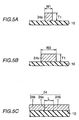
- Fig. 5A shows a cross section seen along line A-A in Fig. 4
- Fig. 5B shows a cross section seen along line B-B in Fig.4.
- Fig. 5C shows a cross section seen along line C-C in Fig. 4.
- meltable portion 24a is formed on printed board 10.
- the cross section of meltable portion 24a is generally rectangular.
- the height of meltable portion 24a is T1, and the width thereof is W1.
- interconnection portion 24b is formed on printed board 10.
- the cross section of interconnection portion 24b is generally rectangular.
- the height of interconnection portion 24b is T1 and the width thereof is W2 which is greater than W1.
- the length of meltable portion 24a is L.
- meltable portion 24a is smaller than the cross sectional area of interconnection portion 24b. Therefore, when interconnection layer is supplied with current, the density of current passing through interconnection portion 24b is relatively small, and the density of current passing through meltable portion 24a is greater. Accordingly, meltable portion 24a rapidly generates heat when current exceeds a prescribed value. This heat generation melts meltable portion 24a. Interconnection layer 24 is thereby broken.
- meltable portion 24a Smaller cross sectional area (T1 x W1) of meltable portion 24a increases the resistance of meltable portion 24a, so that meltable portion 24a can be melted and cut off with a small current.
- longer length L of meltable portion 24a increases the resistance of meltable portion 24a, so that meltable portion 24a can be melted and cut off with a small current. Therefore, the value of current at which meltable portion 24a is melted and cut off can be set by adjusting the length and cross sectional area of meltable portion 24a. For example, when height T1, width W1 and length L are respectively set to about 35 ⁇ m, about 150 ⁇ m and 10 mm, meltable portion 24a is melted and cut off at about 7 amperes. When two such interconnection layers are disposed in parallel, meltable portion 24a is melted and cut off at about 14 amperes.
- Fig. 6 the battery-protecting function by interconnection layer 24 and current-amount control circuit 50 will be described.
- the ordinate and the abscissa respectively represent voltage and current.
- A represents a charge-guaranteed region in which the battery is rechargeable without damage
- B represents a protection region in which the current and temperature detecting circuit (for example a PTC element, a thermal protector and the like) forming current-amount control circuit 50 can function.
- C represents a protection region of the interconnection layer.
- Charge-guaranteed region A in which the battery is rechargeable without damage ranges from 0 ampere to F0 ampere.
- F0 is about (2+ ⁇ ) amperes.
- Protection region B of the current and temperature detecting circuit ranges from the current value F1 to the current value F2, and the current value F1 is included in the boundary region of charge-guaranteed region A.
- F1 is about 2 amperes
- F2 is about (12+ ⁇ ) amperes.
- interconnection layer 24 is formed such that meltable portion 24a is melted when the value of current flowing in the battery becomes equal to or more than F3.
- the current value F3 is set to a value included in the boundary region of the protection region of the current and temperature detecting circuit. In the figure, F3 is about 12 amperes.
- interconnection layer 24 is formed such that the protection region by interconnection layer 24 (the current region in which meltable portion 24a is melted and the interconnection layer is cut off) overlaps the boundary value of the protection region of the current and temperature detecting circuit.
- the battery can be charged without damage.
- the current and temperature detecting circuit When the value of current flowing in the battery enters protection region B, the current and temperature detecting circuit operates to increase its resistance and decrease the current flowing into the battery. At this point, current-amount control circuit 50 performs its protecting function from the vicinity of the boundary value of charge-guaranteed region A of the battery.
- meltable portion 24a is melted, and interconnection layer 24 is cut off, so that the current flowing in current-amount control circuit 50 and battery 20 is interrupted. Therefore, a short between PTC elements due to carbonization of PTC element caused by the current exceeding protection region B can be prevented. Furthermore, the current-limiting effect by PTC element 55 has a time delay, of which effect on battery 20 can also be prevented.
- charge-guaranteed region A and protection region B of current and temperature detecting circuit overlap that portion in which the current value is not less than F1 and not more than F0
- charge-guaranteed region A of the battery which is at the left side of these regions
- protection region B of the current and temperature detecting circuit and protection region C of the interconnection layer overlap that portion in which the current value is not less than F3 and not more than F2
- protection region B of the current and temperature detecting circuit which is at the left side of these regions, is designed to function with priority.
- PTC element 55 when a short or the like causes heavy current to flow in battery core 21, PTC element 55 can operate to decrease the value of current flowing in battery core 21.
- meltable portion 24a when it comes close to such an environment that is out of the condition ensuring normal operation of PTC element 55 due to charge at an overvoltage, charge in reverse direction or the like, meltable portion 24a is melted and cut off.
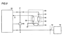
- FIG. 7 An example of such a relation between interconnection layer 24 and the current-amount control circuit is as shown in Figs. 7 to 9.
- current-amount control circuit 50 is configured with PTC element 55 and thermistor 56.
- Interconnection layer 24 and PTC element 55 are connected between the positive terminal of battery 20 and main circuit 30, and thermistor 56 is connected with the side of the negative terminal of battery 20.
- interconnection layer 24 is arranged between main circuit 30 and the positive terminal of battery 20, and PTC element and thermistor 26 configuring current-amount control circuit 50 is connected with the side of the negative terminal of battery 20.
- PTC element 55 and thermistor 26 configuring current-amount control circuit 50 is connected with the side with lower potential.
- Interconnection layer 24 is connected between PTC element 55 and a ground terminal.
- Figs. 7 to 9 show PTC element 55 and thermistor 56 configuring current-amount control circuit 50, but this invention is not limited thereto.
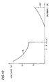
- Fig. 10 is a graph showing the relation between the value of current and the time at which each element may function, in the battery protective circuit in accordance with the second embodiment of the present invention.
- the ordinate shows the time required for each element to start an operation
- the abscissa shows the current value.
- Curve 110 shows the relation between the time and the value of current at which the current and temperature detecting circuit (such as a PTC element, a thermal protector or the like) configuring current-amount control circuit 50 may operate.
- Curve 120 shows the relation between the time and the value of current necessary for meltable portion 24a of interconnection layer 24 to be melted and cut off. Referring to Fig.
- the protection region of the current and temperature detecting circuit ranges from the current value F1 to the current value F2, and the current value F1 is included in the boundary region of the charge-guaranteed region.
- meltable portion 24a is melted when the value of current flowing in the battery reaches equal to or more than F3.
- the current value F3 is set to be a value which is included in the boundary region of the protection region of the current and temperature detecting circuit.
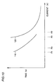
- Fig. 5A Three interconnection layers 24 were prepared, with 0.2 mm of the width W1, 35 ⁇ m of thickness T1, and 10 mm of the length of meltable portion 24a shown in Fig. 5A. These were connected in parallel, and in this interconnection layer, the time and the value of current at which the meltable portion began melting were measured in a high temperature atmosphere and a low temperature atmosphere. Further, the time and the value of current at which PTC began operating were measured in a high temperature atmosphere and a low temperature atmosphere. The result is shown in Fig. 11. In Fig. 11, the ordinate shows the time required for each element to start an operation, and the abscissa shows the current value. Curve 201 shows the relation between the time and the value of current necessary for PTC to operate in the high temperature atmosphere.
- Curve 202 shows the relation between the time and the value of current necessary for PTC to operate in the low temperature atmosphere.
- Curve 203 shows the relation between the time and the value of current necessary for meltable portion 24a to be melted and cut off in the high temperature atmosphere.
- Curve 204 shows the relation between the time and the value of current necessary for meltable portion 24a to be melted and cut off.
- Fig. 11 in the interconnection layer in accordance with this invention, as the value of current at which meltable portion 24a is melted and cut off becomes greater, the time required for meltable portion 24a to start melting and cutting off becomes shorter. In addition, it can be seen that meltable portion 24a is melted and cut off in a shorter time in the high temperature atmosphere compared with in the low temperature atmosphere.
- an external short (so called chain-short) with not more than 50 m ⁇ of resistance value and about one second of the duration may not melt and cut off meltable portion 24a, and therefore the battery can be reused.
- a portable telephone is taken as an example of a personal digital assistant
- the present invention is not limited thereto, and may be applied to a notebook-sized personal computer, a video tape recorder and the like.
- any of a lithium cell, a nickel-cadmium battery and a polymer battery may be used as battery 20.
- PTC element 55 and thermistor 56 and interconnection layer 24 which are arranged for the positive terminal 22 and the negative terminal 23 of the battery is not limited to the one described above.
- interconnection portion 24b may be formed of a material with higher melting point and meltable portion 24a may be formed of a material with lower melting point.
- the number of interconnection layers 24 is not limited to one, but may be changed properly as needed. In case where a plurality of interconnection layers 24 are provided, any one of meltable portion 24a is surely melted, and therefore the reliability of the device is further improved.
- the shape of the meltable portion in the interconnection layer is not limited to the linear shape as shown.
- the meltable portion may be formed, for example, to extend in a serpentine shape in order to secure the length.
- the value of current flowing into the battery increases, the value of current can be decreased before degradation and damage of the battery.
- the battery can surely be protected, and the reliability and safety of the battery and the device operated by the battery can be improved.
- the current amount approaches the boundary region of the operating condition of the current and temperature detecting circuit, due to overcharge, charge in reverse direction or the like, the interconnection layer is melted and cut off at the time when the current-amount control circuit is not yet damaged, and the current is interrupted.
- the undesirably high temperature of the battery can be prevented, and in addition, the current-amount control circuit may not be burdened. As a result, the reliability and safety of the battery and the device operated by the battery can be improved.
- a plurality of the interconnection layers having meltable portions may be provided, so that current can be interrupted at respective different positions when it enters the protection region of the interconnection layer.
- the reliability can be enhanced.
- a battery protective circuit in accordance with the present invention can be applied to a portable telephone, a notebook-sized personal computer, a word processor, a liquid crystal television, a VTR with camera and the like.
Landscapes
- Engineering & Computer Science (AREA)
- Power Engineering (AREA)
- Microelectronics & Electronic Packaging (AREA)
- Manufacturing & Machinery (AREA)
- Chemical & Material Sciences (AREA)
- Chemical Kinetics & Catalysis (AREA)
- Electrochemistry (AREA)
- General Chemical & Material Sciences (AREA)
- Protection Of Static Devices (AREA)
- Connection Of Batteries Or Terminals (AREA)
- Charge And Discharge Circuits For Batteries Or The Like (AREA)
Abstract
A battery protective circuit which can ensure the safety and
reliability of a rechargeable secondary battery is provided. Personal
digital assistants include a main circuit (30) and a battery block (60). The
battery block (60) includes a battery (20) and a current-amount control
circuit (50). The battery (20) is charged via an AC adapter. The current-amount
control circuit (50) includes a current and temperature detecting
circuit (for example a PTC element) operative to reduce a current amount
when an amount of current flowing in the battery (20) approaches a
boundary value of a charge-guaranteed region in which the battery (20) is
rechargeable.
Description
The present invention relates to a battery protective circuit, and
more particularly to a configuration for preventing a value of current
flowing in a battery from exceeding a guaranteed current when a short or
overcharge occurs.
Recently, personal digital assistants such as a portable telephone, a
notebook-sized personal computer and a video camera are widely used.
These personal digital assistants use a battery for supplying power. A
rechargeable secondary battery is used for such a battery.
When current flowing in a battery increases for some reason (a short
of an electric circuit or charge at an overvoltage and the like), the battery
may generate excessive heat and possibly become degraded or damaged.
Therefore, these tools are conventionally equipped with a battery
protective circuit for protecting the battery. An example of the battery
protective circuit includes a PTC (Positive Temperature Coefficient)
element and a thermal protector. The PTC element or the thermal
protector serves as a current and temperature detecting circuit, operating
in such a manner that electric resistance thereof increases as a larger
current flows in the element and temperature becomes higher, and electric
resistance thereof increases rapidly to suppress current when a certain
temperature is reached. Further, a thermistor has its resistance value
changed as an ambient temperature rises.
The conventional battery protective circuit, however, has a problem
as described below. Referring to Fig. 12, the problem of the conventional
battery protective circuit will be described.
With respect to Fig. 12, the ordinate and the abscissa respectively
represent voltage and current. A represents a charge-guaranteed region
in which a battery is rechargeable, and BZ represents a protection region in
which a current and temperature detecting circuit such as a PTC element
or a thermal protector is functional.
The charge-guaranteed region A represents a relation between
current flowing in the battery and voltage across terminals of the battery.
The protection region BZ represents a relation between current flowing in
the PTC element or the like (and the battery) and voltage across terminals
of the PTC element or the like.
The charge-guaranteed region A is a region in which the battery can
protect itself, and the protection region BZ is a region in which the current
and temperature detecting circuit is functional.
When the value of current flowing in the battery enters the
protection region BZ for some reason, the internal resistance of the PTC
element or the like increases. As a result, an amount of current flowing in
the circuit decreases.
The conventional battery protective circuit has performed its
protecting function when heavy current flows, regardless of the charge-guaranteed
region A, as shown in Fig. 12.
Therefore, for the current value between the charge-guaranteed
region A and the protection region BZ, any safety and reliability of the
battery is not assured. Thus, unfortunately, for some types of batteries,
the battery cannot protect itself, and in addition, the safety and reliability
of a device operated by the battery cannot be assured.
Then, the present invention is made to solve the above mentioned
problem, and its object is to provide a battery protective circuit which can
ensure the safety and reliability of a rechargeable battery and a device
operated by the battery.
According to an aspect, the present invention provides a battery
protective circuit for a rechargeable battery, including a current-amount
control circuit including a current and temperature detecting circuit
provided near the battery, operative to detect a value of current flowing in
the battery and an ambient temperature, and to decrease the current value
when the current value and the ambient temperature reach a value of a
protection region, wherein the minimum current value in the protection
region is less than the maximum current value in the charge-guaranteed
region in which the battery is rechargeable, and the maximum current
value in the protection region is greater than the maximum current value
in the charge-guaranteed region.
According to another aspect, the present invention provides a battery
protective circuit for a rechargeable battery, including: a current-amount
control circuit including a current and temperature detecting circuit
provided near the battery, operative to detect a value of current flowing in
the battery and an ambient temperature, and to decrease the current value
when the current value and the ambient temperature reach a value of a
first protection region; and an interconnection layer supplying current to be
flown in the battery, including a meltable portion to be melted and cut off
when the value of current flowing in the battery reaches a value of a second
protection region. The minimum current value in the first protection region
is less than the maximum current value in the charge-guaranteed region in
which the battery is rechargeable, and the maximum current value in the
first protection region is greater than the maximum current value in the
charge-guaranteed region. The minimum current value in the second
protection region is less than the maximum current value in the first
protection region, and the minimum current value in the second protection
region is greater than the maximum current value in the charge-guaranteed
region. In the interconnection layer, the meltable portion has
a relatively small cross sectional area, while a portion other than the
meltable portion of the interconnection layer has a relatively large cross
sectional area.
Preferably, at least two or more meltable portions of the
interconnection layer are arranged.
The aforementioned battery protective circuit can decrease the
current value before degradation and damage of the battery, even when the
value of current flowing into the battery increases.
As a result, the battery can surely be protected, and the safety and
reliability of the battery and the device operated by the battery can be
improved.
Further, when the current amount approaches a boundary region of
an operating condition of the current and temperature detecting circuit due
to overcharge, charge in reverse direction or the like, the interconnection
layer is melted and cut off at the time when the current-amount control
circuit is not yet damaged, and therefore the current is interrupted.
Therefore, the undesirably high temperature of the battery can be
prevented and the current-amount control circuit may not be burdened.
As a result, the overall reliability and safety of the device including the
battery and the current-amount control circuit can be improved.
According to a further aspect, the present invention provides a
battery protective circuit for a rechargeable battery, including: a current-amount
control circuit including a current and temperature detecting
circuit provided near the battery, operative to detect a value of current
flowing in the battery and an ambient temperature, and to decrease the
current value when the current value and the ambient temperature reach a
value of a first protection region; and an interconnection layer supplying
current to be flown in the battery, including a meltable portion to be melted
and cut off when the value of current flowing in the battery reaches a value
of a second protection region. The minimum current value in the first
protection region is less than the maximum current value in the charge-guaranteed
region in which the battery is rechargeable, and the maximum
current value in the first protection region is greater than the maximum
current value in the charge-guaranteed region. The minimum current
value in the second protection region is less than the maximum current
value in the first protection region, and the minimum current value in the
second protection region is greater than the maximum current value in the
charge-guaranteed region. In the interconnection layer, the meltable
portion has a relatively small cross sectional area, while a portion other
than the meltable portion of the interconnection layer has a relatively large
cross sectional area. In the interconnection layer, the greater the current
value in the second protection, the shorter the time for the meltable portion
be melted and cut off.
The aforementioned battery protective circuit can decrease the
current value before degradation and damage of the battery, even when the
value of current flowing into the battery increases, so that the battery can
surely be protected, and in addition, the safety and reliability of the battery
and the device operated by the battery can be improved. Furthermore,
when the current amount approaches a boundary region of an operating
condition of the current and temperature detecting circuit due to
overcharge, charge in reverse direction or the like, the interconnection layer
is melted and cut off at the time when the current-amount control circuit is
not yet damaged, and the current is interrupted. Therefore, the
undesirably high temperature of the battery can be prevented and the
current-amount control circuit may not be burdened. As a result, the
overall reliability and safety of the device including the battery and the
current-amount control circuit can be improved. Further, as the current
value in the second protection region becomes greater, the time for the
meltable portion to be melted and cut off becomes shorter. Therefore, even
when heavy current flows, the meltable portion is not melted and cut off, if
the time of current flow is short enough. As a result, even when the
terminal of the battery causes a momentary short-circuit, the meltable
portion does not melt, if the moment is short enough. Therefore, a short
circuit over such a short time that does not affect the safety may not result
in a failure of the battery.
Embodiments of the present invention will be described with
reference to the figures. Note that the same or corresponding parts in the
figures are denoted with the same reference characters and the description
thereof is not repeated.
Referring to Fig. 1, a configuration for battery protection in
accordance with a first embodiment will be described. It is noted that in
the following description, a portable telephone is taken as an example of a
personal digital assistant for the purpose of illustration. Fig. 1 shows a
configuration of a main portion of a portable telephone in accordance with
the first embodiment.
Turning now to Fig. 1, the portable telephone includes a main circuit
30 including a processing circuit and the like for sending and receiving a
signal, a battery block 60 for supplying electricity to main circuit 30, and a
control circuit 80.
Current-amount control circuit 50 is configured, for example, with a
PTC element which is a current and temperature detecting circuit, a
thermistor or the like which is a temperature sensing element, or a
composite element thereof. The current and temperature detecting circuit
as used herein refers to a PTC element, a thermal protector or the like, and
it has a function of continuously detecting a current value and a
temperature to control the value of current. It is noted that current is
interrupted by the current and temperature detecting circuit when a
certain value of current and temperature are reached. In Fig. 1, current-amount
control circuit 50 is configured with PTC element 55. PTC
element 55 is connected to the side of the negative terminal of battery 20.
Furthermore, main circuit 30 includes a circuit (such as a clock)
operated by supply voltage received from node R, which is electrically
connected to AC adapter terminal 72.
Referring now to Fig. 2, the battery-protecting function by current-amount
control circuit 50 in accordance with the first embodiment will be
described. In Fig. 2, the ordinate and the abscissa respectively represent
voltage and current, A represents a charge-guaranteed region in which the
battery is rechargeable without damage, and B represents the protection
region in which the current and temperature detecting circuit (PTC
element 55) in accordance with the first embodiment is functional.
The charge-guaranteed region A is a region in which the battery is
rechargeable without damage, that is, the battery can protect itself.
Charge-guaranteed region A ranges from 0 ampere to F0 ampere. In the
figure, F0 is about (2+ α) amperes (the current value varies with battery
rating).
The protection region B of the current and temperature detecting
circuit is a region where the battery is protected. Protection region B
ranges from the current value F1 to the current value F2. The current
value F1 is included in a boundary region of charge-guaranteed region A.
In the figure, F1 is about 2 amperes, and F2 is about (12+β) amperes.
As the value of current flowing in battery 20 enters protection region
B, the current and temperature detecting circuit operates to increase its
resistance and decrease the current flowing into battery 20. At this point,
the current and temperature detecting circuit performs its protecting
function from the vicinity of boundary value of charge-guaranteed region A
of battery 20. Therefore, when the value of current flowing in battery 20
gets close to the boundary value of charge-guaranteed region A, the value of
current flowing into battery 20 can be shifted to charge-guaranteed region
A.
As a result, degradation and damage of battery 20 can surely be
prevented, and the overall safety and reliability of the device including the
battery can be assured.
Note that the configuration of current-amount control circuit 50 is
not limited to the one shown in Fig. 1. As an example of current-amount
control circuit 50, a thermal protector may be used. Further, as shown in
Fig. 3, battery 20 may have its positive terminal connected to PTC element
55 and its negative terminal connected to a temperature sensing element
56, such as a thermistor.
A configuration for battery protection in accordance with a second
embodiment will be now described. According to the second embodiment,
an interconnection layer having a meltable portion to be melted and cut off
in accordance with a current value is arranged in addition to the above
mentioned current-amount control circuit 50, for battery 20.
Fig. 4 illustrates a structure of a main portion of a portable telephone
in accordance with the second embodiment of the present invention.
Referring to Fig. 4, a portable telephone 1 includes a housing 2, a printed
board 10 as an insulating substrate, a main circuit 30, a battery 20 and an
antenna 40. A large part of antenna 40 is accommodated in housing 2,
and can be extended to protrude from housing 2 when portable telephone 1
is used.
Printed board 10 is fixed to housing 2. Main circuit 30 is provided
on printed board 10. Main circuit 30 is supplied with electricity from
battery 20.
An interconnection layer 24 and PTC element 55 as a current-amount
control circuit are also arranged on printed board 10. PTC
element 55 and interconnection layer 24 are connected between positive
terminal 22 and main circuit 30. An interconnection layer 31 is connected
between negative terminal 23 and the main circuit.
Fig. 5A shows a cross section seen along line A-A in Fig. 4, and Fig.
5B shows a cross section seen along line B-B in Fig.4. Fig. 5C shows a
cross section seen along line C-C in Fig. 4.
Referring to Fig. 5A, meltable portion 24a is formed on printed board
10. The cross section of meltable portion 24a is generally rectangular.
The height of meltable portion 24a is T1, and the width thereof is W1.
Referring to Fig. 5B, interconnection portion 24b is formed on printed board
10. The cross section of interconnection portion 24b is generally
rectangular. The height of interconnection portion 24b is T1 and the
width thereof is W2 which is greater than W1. Referring to Fig. 5C, the
length of meltable portion 24a is L.
The cross sectional area of meltable portion 24a is smaller than the
cross sectional area of interconnection portion 24b. Therefore, when
interconnection layer is supplied with current, the density of current
passing through interconnection portion 24b is relatively small, and the
density of current passing through meltable portion 24a is greater.
Accordingly, meltable portion 24a rapidly generates heat when current
exceeds a prescribed value. This heat generation melts meltable portion
24a. Interconnection layer 24 is thereby broken.
Smaller cross sectional area (T1 x W1) of meltable portion 24a
increases the resistance of meltable portion 24a, so that meltable portion
24a can be melted and cut off with a small current. Alternatively, longer
length L of meltable portion 24a increases the resistance of meltable
portion 24a, so that meltable portion 24a can be melted and cut off with a
small current. Therefore, the value of current at which meltable portion
24a is melted and cut off can be set by adjusting the length and cross
sectional area of meltable portion 24a. For example, when height T1,
width W1 and length L are respectively set to about 35 µm, about 150 µm
and 10 mm, meltable portion 24a is melted and cut off at about 7 amperes.
When two such interconnection layers are disposed in parallel, meltable
portion 24a is melted and cut off at about 14 amperes.
Referring now to Fig. 6, the battery-protecting function by
interconnection layer 24 and current-amount control circuit 50 will be
described. In Fig. 6, the ordinate and the abscissa respectively represent
voltage and current. A represents a charge-guaranteed region in which
the battery is rechargeable without damage, and B represents a protection
region in which the current and temperature detecting circuit (for example
a PTC element, a thermal protector and the like) forming current-amount
control circuit 50 can function. Further, C represents a protection region
of the interconnection layer.
Charge-guaranteed region A in which the battery is rechargeable
without damage ranges from 0 ampere to F0 ampere. In the figure, F0 is
about (2+α) amperes.
Protection region B of the current and temperature detecting circuit
ranges from the current value F1 to the current value F2, and the current
value F1 is included in the boundary region of charge-guaranteed region A.
In the figure, F1 is about 2 amperes, and F2 is about (12+β) amperes.
In this case, interconnection layer 24 is formed such that meltable
portion 24a is melted when the value of current flowing in the battery
becomes equal to or more than F3. Here, the current value F3 is set to a
value included in the boundary region of the protection region of the
current and temperature detecting circuit. In the figure, F3 is about 12
amperes.
In other words, in the second embodiment, interconnection layer 24
is formed such that the protection region by interconnection layer 24 (the
current region in which meltable portion 24a is melted and the
interconnection layer is cut off) overlaps the boundary value of the
protection region of the current and temperature detecting circuit.
If the current flowing in the battery has a current value within
charge-guaranteed region A (0 ampere to F0 ampere), the battery can be
charged without damage.
When the value of current flowing in the battery enters protection
region B, the current and temperature detecting circuit operates to increase
its resistance and decrease the current flowing into the battery. At this
point, current-amount control circuit 50 performs its protecting function
from the vicinity of the boundary value of charge-guaranteed region A of
the battery.
Further, when the value of current flowing in the battery gets close
to the boundary value of protection region B, meltable portion 24a is melted,
and interconnection layer 24 is cut off, so that the current flowing in
current-amount control circuit 50 and battery 20 is interrupted. Therefore,
a short between PTC elements due to carbonization of PTC element caused
by the current exceeding protection region B can be prevented.
Furthermore, the current-limiting effect by PTC element 55 has a time
delay, of which effect on battery 20 can also be prevented.
It is noted that in the portion where two regions overlap, for example,
in the region where charge-guaranteed region A and protection region B of
current and temperature detecting circuit overlap (that portion in which
the current value is not less than F1 and not more than F0), charge-guaranteed
region A of the battery, which is at the left side of these regions,
is designed to function with priority. Further, in the region where
protection region B of the current and temperature detecting circuit and
protection region C of the interconnection layer overlap (that portion in
which the current value is not less than F3 and not more than F2),
protection region B of the current and temperature detecting circuit, which
is at the left side of these regions, is designed to function with priority.
In this manner, according to the second embodiment, when a short or
the like causes heavy current to flow in battery core 21, PTC element 55
can operate to decrease the value of current flowing in battery core 21. In
addition, when it comes close to such an environment that is out of the
condition ensuring normal operation of PTC element 55 due to charge at an
overvoltage, charge in reverse direction or the like, meltable portion 24a is
melted and cut off.
Since this can interrupt the current, the undesirably high
temperature of battery core 21 can be prevented. In addition, degradation
and damage of current-amount control circuit 50 can be prevented. As a
result, the overall safety and reliability of the device including the battery
can be assured.
An example of such a relation between interconnection layer 24 and
the current-amount control circuit is as shown in Figs. 7 to 9. In an
example shown in Fig. 7, current-amount control circuit 50 is configured
with PTC element 55 and thermistor 56. Interconnection layer 24 and
PTC element 55 are connected between the positive terminal of battery 20
and main circuit 30, and thermistor 56 is connected with the side of the
negative terminal of battery 20.
In an example shown in Fig. 8, interconnection layer 24 is arranged
between main circuit 30 and the positive terminal of battery 20, and PTC
element and thermistor 26 configuring current-amount control circuit 50 is
connected with the side of the negative terminal of battery 20.
Further, in an example shown in Fig. 9, PTC element 55 and
thermistor 26 configuring current-amount control circuit 50 is connected
with the side with lower potential. Interconnection layer 24 is connected
between PTC element 55 and a ground terminal.
Figs. 7 to 9 show PTC element 55 and thermistor 56 configuring
current-amount control circuit 50, but this invention is not limited thereto.
Fig. 10 is a graph showing the relation between the value of current
and the time at which each element may function, in the battery protective
circuit in accordance with the second embodiment of the present invention.
In Fig. 10, the ordinate shows the time required for each element to start
an operation, and the abscissa shows the current value. Curve 110 shows
the relation between the time and the value of current at which the current
and temperature detecting circuit (such as a PTC element, a thermal
protector or the like) configuring current-amount control circuit 50 may
operate. Curve 120 shows the relation between the time and the value of
current necessary for meltable portion 24a of interconnection layer 24 to be
melted and cut off. Referring to Fig. 10, as shown with curve 110, as the
value of current flowing in the temperature detecting circuit (such as a PTC
element, a thermal protector or the like) becomes greater, the time required
for current-amount control circuit 50 to start an operation becomes shorter.
Similarly, as shown with curve 120, as the value of current flowing in
interconnection layer 24 becomes greater, the time required for meltable
portion 24a to start melting and cutting off becomes shorter. Both of curve
110 and curve 120 are convex downward, which shows that the
corresponding element takes shorter time to operate as the current value
becomes greater.
The protection region of the current and temperature detecting
circuit ranges from the current value F1 to the current value F2, and the
current value F1 is included in the boundary region of the charge-guaranteed
region.
In this case, for interconnection layer 24, meltable portion 24a is
melted when the value of current flowing in the battery reaches equal to or
more than F3. Here, the current value F3 is set to be a value which is
included in the boundary region of the protection region of the current and
temperature detecting circuit.
Next, three interconnection layers 24 were prepared, with 0.2 mm of
the width W1, 35 µm of thickness T1, and 10 mm of the length of meltable
portion 24a shown in Fig. 5A. These were connected in parallel, and in
this interconnection layer, the time and the value of current at which the
meltable portion began melting were measured in a high temperature
atmosphere and a low temperature atmosphere. Further, the time and the
value of current at which PTC began operating were measured in a high
temperature atmosphere and a low temperature atmosphere. The result is
shown in Fig. 11. In Fig. 11, the ordinate shows the time required for each
element to start an operation, and the abscissa shows the current value.
Curve 201 shows the relation between the time and the value of current
necessary for PTC to operate in the high temperature atmosphere. Curve
202 shows the relation between the time and the value of current necessary
for PTC to operate in the low temperature atmosphere. Curve 203 shows
the relation between the time and the value of current necessary for
meltable portion 24a to be melted and cut off in the high temperature
atmosphere. Curve 204 shows the relation between the time and the value
of current necessary for meltable portion 24a to be melted and cut off. As
can be seen from Fig. 11, in the interconnection layer in accordance with
this invention, as the value of current at which meltable portion 24a is
melted and cut off becomes greater, the time required for meltable portion
24a to start melting and cutting off becomes shorter. In addition, it can be
seen that meltable portion 24a is melted and cut off in a shorter time in the
high temperature atmosphere compared with in the low temperature
atmosphere.
For the protective circuit in accordance with the present invention,
an external short (so called chain-short) with not more than 50 mΩ of
resistance value and about one second of the duration may not melt and cut
off meltable portion 24a, and therefore the battery can be reused.
Although the first and second embodiments have been described
above, various modifications may be made on the embodiments described
herein.
Although a portable telephone is taken as an example of a personal
digital assistant, the present invention is not limited thereto, and may be
applied to a notebook-sized personal computer, a video tape recorder and
the like.
Any of a lithium cell, a nickel-cadmium battery and a polymer
battery may be used as battery 20.
The relation between PTC element 55 and thermistor 56 and
interconnection layer 24 which are arranged for the positive terminal 22
and the negative terminal 23 of the battery is not limited to the one
described above.
Various kinds of material can be used rather than copper and the
like, as a material of interconnection layer 24. More specifically,
interconnection portion 24b may be formed of a material with higher
melting point and meltable portion 24a may be formed of a material with
lower melting point.
Further, the number of interconnection layers 24 is not limited to one,
but may be changed properly as needed. In case where a plurality of
interconnection layers 24 are provided, any one of meltable portion 24a is
surely melted, and therefore the reliability of the device is further improved.
Still further, the shape of the meltable portion in the interconnection
layer is not limited to the linear shape as shown. The meltable portion
may be formed, for example, to extend in a serpentine shape in order to
secure the length.
In accordance with the present invention, even when the value of
current flowing into the battery increases, the value of current can be
decreased before degradation and damage of the battery. As a result, the
battery can surely be protected, and the reliability and safety of the battery
and the device operated by the battery can be improved.
In accordance with the present invention, the current amount
approaches the boundary region of the operating condition of the current
and temperature detecting circuit, due to overcharge, charge in reverse
direction or the like, the interconnection layer is melted and cut off at the
time when the current-amount control circuit is not yet damaged, and the
current is interrupted.
Therefore, the undesirably high temperature of the battery can be
prevented, and in addition, the current-amount control circuit may not be
burdened. As a result, the reliability and safety of the battery and the
device operated by the battery can be improved.
In addition, in accordance with the present invention, a plurality of
the interconnection layers having meltable portions may be provided, so
that current can be interrupted at respective different positions when it
enters the protection region of the interconnection layer. In particular,
when the identical interconnection layers are provided in parallel, the
reliability can be enhanced.
Although the present invention has been described and illustrated in
detail, it is clearly understood that the same is by way of illustration and
example only and is not to be taken by way of limitation, the spirit and
scope of the present invention being limited only by the terms of the
appended claims.
A battery protective circuit in accordance with the present invention
can be applied to a portable telephone, a notebook-sized personal computer,
a word processor, a liquid crystal television, a VTR with camera and the
like.
Claims (4)
- A battery protective circuit for a rechargeable battery, comprisingwherein a minimum current value in said protection region is less than a maximum current value in a charge-guaranteed region in which said battery is rechargeable, and a maximum current value in said protection region is greater than the maximum current value in said charge-guaranteed region.a current-amount control circuit including a current and temperature detecting circuit provided near said battery, operative to detect a value of current flowing in said battery and an ambient temperature and to decrease said current value when said current value and said ambient temperature reach a value of a protection region,
- A battery protective circuit for a rechargeable battery, comprising:a current-amount control circuit including a current and temperature detecting circuit provided near said battery, operative to detect a value of current flowing in said battery and an ambient temperature and to decrease said current value when said current value and said ambient temperature reach a value of a first protection region; andan interconnection layer supplying current to be flown in said battery, including a meltable portion to be melted and cut off when a value of current flowing in said battery reaches a value of second protection region, whereina minimum current value in said first protection region is less than a maximum current value in a charge-guaranteed region in which said battery is rechargeable, a maximum current value in said first protection region is greater than the maximum current value in said charge-guaranteed region,a minimum current value in said second protection region is less than the maximum current value in said first protection region, the minimum current value in said second protection region is greater than the maximum current value in said charge-guaranteed region, andin said interconnection layer, said meltable portion has a relatively small cross sectional area, while a portion other than the meltable portion in said interconnection layer has a relatively large cross sectional area.
- The battery protective circuit according to claim 2, wherein at least two meltable portions of said interconnection layer are arranged.
- A battery protective circuit for a rechargeable battery, comprising:a current-amount control circuit including a current and temperature detecting circuit provided near said battery, operative to detect a value of current flowing in said battery and an ambient temperature and to decrease said current value when said current value and said ambient temperature reach a value of a first protection region; andan interconnection layer supplying current to be flown in said battery, including a meltable portion to be melted and cut off when said value of current flowing in the battery reaches a value of second protection region, whereina minimum current value in said first protection region is less than a maximum current value in a charge-guaranteed region in which said battery is rechargeable, a maximum current value in said first protection region is greater than the maximum current value in said charge-guaranteed region,a minimum current value in said second protection region is less than the maximum current value in said first protection region, a minimum current value in said second protection region is greater than maximum current value in said charge-guaranteed region,in said interconnection layer, said meltable portion has a relatively small cross sectional area, while a portion other than the meltable portion of said interconnection layer has a relatively large cross sectional area, andin said interconnection layer, as a current value in said second protection region becomes greater, time for said meltable portion to be melted and cut off becomes shorter.
Applications Claiming Priority (3)
| Application Number | Priority Date | Filing Date | Title |
|---|---|---|---|
| JP2000072390 | 2000-03-15 | ||
| JP2000072390 | 2000-03-15 | ||
| PCT/JP2000/006794 WO2001069748A1 (en) | 2000-03-15 | 2000-09-29 | Cell protective circuit |
Publications (2)
| Publication Number | Publication Date |
|---|---|
| EP1182763A1 true EP1182763A1 (en) | 2002-02-27 |
| EP1182763A4 EP1182763A4 (en) | 2004-09-01 |
Family
ID=18590812
Family Applications (1)
| Application Number | Title | Priority Date | Filing Date |
|---|---|---|---|
| EP00962999A Withdrawn EP1182763A4 (en) | 2000-03-15 | 2000-09-29 | PROTECTIVE CIRCUIT FOR BATTERY |
Country Status (5)
| Country | Link |
|---|---|
| US (2) | US6462515B1 (en) |
| EP (1) | EP1182763A4 (en) |
| KR (1) | KR100450361B1 (en) |
| CN (1) | CN1269281C (en) |
| WO (1) | WO2001069748A1 (en) |
Families Citing this family (16)
| Publication number | Priority date | Publication date | Assignee | Title |
|---|---|---|---|---|
| CN1269281C (en) * | 2000-03-15 | 2006-08-09 | 三菱电机株式会社 | Battery protection circuit |
| JP2007520180A (en) * | 2003-10-14 | 2007-07-19 | ブラック アンド デッカー インク | Secondary battery, power tool, charger, and protection method, protection circuit, and protection device for battery pack adapted to provide protection from battery pack failure conditions |
| US7145444B2 (en) * | 2003-12-05 | 2006-12-05 | Trw Automotive U.S. Llc | Circuit for controlling voltage in a tire-based unit of tire parameter sensing system and associated method |
| US7363518B2 (en) * | 2004-07-22 | 2008-04-22 | Dell Products L.P. | Information handling system with power fault protection circuit |
| JP2008518798A (en) * | 2004-11-08 | 2008-06-05 | ブラック アンド デッカー インク | Ergonomically useful cordless power tool |
| KR100584404B1 (en) | 2004-11-11 | 2006-05-26 | 삼성전자주식회사 | Battery device of mobile communication terminal and its operation method |
| US20060119323A1 (en) * | 2004-12-03 | 2006-06-08 | Don Reed | Temperature responsive charging control circuit |
| KR20060110579A (en) * | 2005-04-20 | 2006-10-25 | 주식회사 엘지화학 | Secondary battery including loop antenna patterned on PC |
| US20070240892A1 (en) * | 2005-11-04 | 2007-10-18 | Black & Decker Inc. | Cordless outdoor power tool system |
| JP4659886B2 (en) * | 2009-01-27 | 2011-03-30 | シャープ株式会社 | Secondary battery protection circuit |
| KR100933864B1 (en) * | 2008-03-31 | 2009-12-24 | 삼성에스디아이 주식회사 | Battery pack |
| JP5415318B2 (en) * | 2010-02-19 | 2014-02-12 | デクセリアルズ株式会社 | Protection circuit, battery control device, and battery pack |
| CN102280902B (en) * | 2010-06-10 | 2014-01-15 | 鸿富锦精密工业(深圳)有限公司 | Protector for battery charging |
| EP3402034B1 (en) * | 2017-05-08 | 2020-03-04 | Braun GmbH | Electrical circuit and method for charging a secondary battery |
| JP7024463B2 (en) * | 2018-02-01 | 2022-02-24 | 株式会社Gsユアサ | Management device, power storage device, management method of power storage element |
| CN111030239B (en) * | 2019-12-24 | 2024-02-13 | 通力科技股份有限公司 | Over-temperature protection charging management circuit, method, device and electronic equipment |
Family Cites Families (12)
| Publication number | Priority date | Publication date | Assignee | Title |
|---|---|---|---|---|
| US5150033A (en) * | 1988-12-09 | 1992-09-22 | Norand Corporation | Flat plate sealed lead-acid battery charging system and method |
| JP2869896B2 (en) * | 1990-09-04 | 1999-03-10 | 株式会社村田製作所 | Overvoltage protection components |
| JP2989313B2 (en) | 1991-04-25 | 1999-12-13 | 三洋電機株式会社 | Battery device having protection element |
| JP3035677B2 (en) * | 1991-09-13 | 2000-04-24 | 旭化成工業株式会社 | Secondary battery with safety element |
| JPH06349480A (en) * | 1993-06-08 | 1994-12-22 | Matsushita Electric Ind Co Ltd | Composite protective element and battery pack with composite protective element |
| US5633573A (en) | 1994-11-10 | 1997-05-27 | Duracell, Inc. | Battery pack having a processor controlled battery operating system |
| JPH08149701A (en) * | 1994-11-25 | 1996-06-07 | Toshiba Battery Co Ltd | Overcurrent protector for secondary battery |
| JP3204178B2 (en) | 1996-10-29 | 2001-09-04 | ソニーケミカル株式会社 | Battery and protection element for battery |
| JPH10172574A (en) | 1996-12-16 | 1998-06-26 | Japan Storage Battery Co Ltd | Battery |
| WO1999039421A1 (en) * | 1998-01-31 | 1999-08-05 | Oglesbee John W | Supplemental battery overcharge protection device |
| CN1269281C (en) * | 2000-03-15 | 2006-08-09 | 三菱电机株式会社 | Battery protection circuit |
| US6977343B2 (en) * | 2000-05-18 | 2005-12-20 | Sony Corporation | Heat-sensitive material and heat-sensitive element |
-
2000
- 2000-09-29 CN CNB008076200A patent/CN1269281C/en not_active Expired - Fee Related
- 2000-09-29 KR KR10-2001-7014492A patent/KR100450361B1/en not_active Expired - Fee Related
- 2000-09-29 US US09/926,528 patent/US6462515B1/en not_active Expired - Lifetime
- 2000-09-29 EP EP00962999A patent/EP1182763A4/en not_active Withdrawn
- 2000-09-29 WO PCT/JP2000/006794 patent/WO2001069748A1/en not_active Ceased
-
2002
- 2002-09-06 US US10/235,787 patent/US6630815B2/en not_active Expired - Lifetime
Also Published As
| Publication number | Publication date |
|---|---|
| WO2001069748A1 (en) | 2001-09-20 |
| CN1269281C (en) | 2006-08-09 |
| KR100450361B1 (en) | 2004-09-30 |
| CN1350712A (en) | 2002-05-22 |
| KR20010113941A (en) | 2001-12-28 |
| US6462515B1 (en) | 2002-10-08 |
| EP1182763A4 (en) | 2004-09-01 |
| US20030011345A1 (en) | 2003-01-16 |
| US6630815B2 (en) | 2003-10-07 |
Similar Documents
| Publication | Publication Date | Title |
|---|---|---|
| US6462515B1 (en) | Cell protective circuit | |
| CN102217118B (en) | Apparatus and method for protecting a battery pack by detecting damage to a sense resistor in the battery pack | |
| EP1107344B1 (en) | Circuit and device for protecting secondary battery | |
| EP1787339B1 (en) | Safety device for preventing overcharge and secondary battery therewith | |
| KR100899425B1 (en) | Protection circuit of battery pack and battery pack having same | |
| EP1189325A2 (en) | Electronic device protection circuit | |
| EP1102338B1 (en) | Ptc element, ptc element-mounted pcb board, secondary cell protection circuit device and secondary cell assembly | |
| KR100890092B1 (en) | Circuit protection device | |
| KR101946106B1 (en) | Protective element and battery pack | |
| KR20150040954A (en) | Protective element and battery pack | |
| US6649302B2 (en) | Temperature sensing device for use in secondary battery pack, and secondary battery pack incorporating the same | |
| WO2020189225A1 (en) | Battery pack and protection circuit | |
| JP3914831B2 (en) | Battery protection circuit | |
| KR20040037547A (en) | Secondary battery pack | |
| JP3420672B2 (en) | Secondary battery protection circuit | |
| KR20050107605A (en) | Polymer ptc device | |
| JP2003070153A (en) | Method for preventing overheat of secondary battery pack | |
| KR200302619Y1 (en) | Secondary battery pack | |
| KR20070108758A (en) | Battery pack manufacturing device | |
| JPWO2001069748A1 (en) | battery protection circuit | |
| KR20220037793A (en) | Battery protection circuit and battery pack including same | |
| KR20070056835A (en) | Battery pack with battery cell protector |
Legal Events
| Date | Code | Title | Description |
|---|---|---|---|
| PUAI | Public reference made under article 153(3) epc to a published international application that has entered the european phase |
Free format text: ORIGINAL CODE: 0009012 |
|
| 17P | Request for examination filed |
Effective date: 20011123 |
|
| AK | Designated contracting states |
Kind code of ref document: A1 Designated state(s): AT BE CH CY DE DK ES FI FR GB GR IE IT LI LU MC NL PT SE |
|
| RBV | Designated contracting states (corrected) |
Designated state(s): DE FR GB |
|
| A4 | Supplementary search report drawn up and despatched |
Effective date: 20040720 |
|
| RAP1 | Party data changed (applicant data changed or rights of an application transferred) |
Owner name: MITSUBISHI DENKI KABUSHIKI KAISHA |
|
| STAA | Information on the status of an ep patent application or granted ep patent |
Free format text: STATUS: THE APPLICATION HAS BEEN WITHDRAWN |
|
| 18W | Application withdrawn |
Effective date: 20080226 |