EP1182477A1 - Optical connector housing, optical connector using the optical connector housing and connection structure between optical connector and optical component using the optical connector housing - Google Patents
Optical connector housing, optical connector using the optical connector housing and connection structure between optical connector and optical component using the optical connector housing Download PDFInfo
- Publication number
- EP1182477A1 EP1182477A1 EP00908063A EP00908063A EP1182477A1 EP 1182477 A1 EP1182477 A1 EP 1182477A1 EP 00908063 A EP00908063 A EP 00908063A EP 00908063 A EP00908063 A EP 00908063A EP 1182477 A1 EP1182477 A1 EP 1182477A1
- Authority
- EP
- European Patent Office
- Prior art keywords
- optical
- optical connector
- ferrule
- housing
- objects
- Prior art date
- Legal status (The legal status is an assumption and is not a legal conclusion. Google has not performed a legal analysis and makes no representation as to the accuracy of the status listed.)
- Withdrawn
Links
Images



Classifications
-
- G—PHYSICS
- G02—OPTICS
- G02B—OPTICAL ELEMENTS, SYSTEMS OR APPARATUS
- G02B6/00—Light guides; Structural details of arrangements comprising light guides and other optical elements, e.g. couplings
- G02B6/24—Coupling light guides
- G02B6/36—Mechanical coupling means
- G02B6/38—Mechanical coupling means having fibre to fibre mating means
- G02B6/3807—Dismountable connectors, i.e. comprising plugs
- G02B6/389—Dismountable connectors, i.e. comprising plugs characterised by the method of fastening connecting plugs and sockets, e.g. screw- or nut-lock, snap-in, bayonet type
- G02B6/3893—Push-pull type, e.g. snap-in, push-on
-
- G—PHYSICS
- G02—OPTICS
- G02B—OPTICAL ELEMENTS, SYSTEMS OR APPARATUS
- G02B6/00—Light guides; Structural details of arrangements comprising light guides and other optical elements, e.g. couplings
- G02B6/24—Coupling light guides
- G02B6/36—Mechanical coupling means
- G02B6/38—Mechanical coupling means having fibre to fibre mating means
- G02B6/3807—Dismountable connectors, i.e. comprising plugs
- G02B6/381—Dismountable connectors, i.e. comprising plugs of the ferrule type, e.g. fibre ends embedded in ferrules, connecting a pair of fibres
- G02B6/3818—Dismountable connectors, i.e. comprising plugs of the ferrule type, e.g. fibre ends embedded in ferrules, connecting a pair of fibres of a low-reflection-loss type
- G02B6/3821—Dismountable connectors, i.e. comprising plugs of the ferrule type, e.g. fibre ends embedded in ferrules, connecting a pair of fibres of a low-reflection-loss type with axial spring biasing or loading means
-
- G—PHYSICS
- G02—OPTICS
- G02B—OPTICAL ELEMENTS, SYSTEMS OR APPARATUS
- G02B6/00—Light guides; Structural details of arrangements comprising light guides and other optical elements, e.g. couplings
- G02B6/24—Coupling light guides
- G02B6/42—Coupling light guides with opto-electronic elements
- G02B6/4292—Coupling light guides with opto-electronic elements the light guide being disconnectable from the opto-electronic element, e.g. mutually self aligning arrangements
-
- G—PHYSICS
- G02—OPTICS
- G02B—OPTICAL ELEMENTS, SYSTEMS OR APPARATUS
- G02B6/00—Light guides; Structural details of arrangements comprising light guides and other optical elements, e.g. couplings
- G02B6/24—Coupling light guides
- G02B6/42—Coupling light guides with opto-electronic elements
- G02B6/43—Arrangements comprising a plurality of opto-electronic elements and associated optical interconnections
-
- G—PHYSICS
- G02—OPTICS
- G02B—OPTICAL ELEMENTS, SYSTEMS OR APPARATUS
- G02B6/00—Light guides; Structural details of arrangements comprising light guides and other optical elements, e.g. couplings
- G02B6/24—Coupling light guides
- G02B6/36—Mechanical coupling means
- G02B6/38—Mechanical coupling means having fibre to fibre mating means
- G02B6/3807—Dismountable connectors, i.e. comprising plugs
- G02B6/381—Dismountable connectors, i.e. comprising plugs of the ferrule type, e.g. fibre ends embedded in ferrules, connecting a pair of fibres
- G02B6/3825—Dismountable connectors, i.e. comprising plugs of the ferrule type, e.g. fibre ends embedded in ferrules, connecting a pair of fibres with an intermediate part, e.g. adapter, receptacle, linking two plugs
-
- G—PHYSICS
- G02—OPTICS
- G02B—OPTICAL ELEMENTS, SYSTEMS OR APPARATUS
- G02B6/00—Light guides; Structural details of arrangements comprising light guides and other optical elements, e.g. couplings
- G02B6/24—Coupling light guides
- G02B6/36—Mechanical coupling means
- G02B6/38—Mechanical coupling means having fibre to fibre mating means
- G02B6/3807—Dismountable connectors, i.e. comprising plugs
- G02B6/3873—Connectors using guide surfaces for aligning ferrule ends, e.g. tubes, sleeves, V-grooves, rods, pins, balls
- G02B6/3874—Connectors using guide surfaces for aligning ferrule ends, e.g. tubes, sleeves, V-grooves, rods, pins, balls using tubes, sleeves to align ferrules
- G02B6/3878—Connectors using guide surfaces for aligning ferrule ends, e.g. tubes, sleeves, V-grooves, rods, pins, balls using tubes, sleeves to align ferrules comprising a plurality of ferrules, branching and break-out means
-
- G—PHYSICS
- G02—OPTICS
- G02B—OPTICAL ELEMENTS, SYSTEMS OR APPARATUS
- G02B6/00—Light guides; Structural details of arrangements comprising light guides and other optical elements, e.g. couplings
- G02B6/24—Coupling light guides
- G02B6/36—Mechanical coupling means
- G02B6/38—Mechanical coupling means having fibre to fibre mating means
- G02B6/3807—Dismountable connectors, i.e. comprising plugs
- G02B6/3873—Connectors using guide surfaces for aligning ferrule ends, e.g. tubes, sleeves, V-grooves, rods, pins, balls
- G02B6/3885—Multicore or multichannel optical connectors, i.e. one single ferrule containing more than one fibre, e.g. ribbon type
Definitions
- the present invention relates to an optical connector housing used for detachably connecting an optical connector mainly employed in optical transmissions and an optical component, an optical connector using the same optical connector housing, and a structure for connecting between an optical connector using the optical connector housing and an optical component.
- optical transmissions using optical fibers have been frequently employed, wherein high bit rate mounting of optical fibers is demanded.
- studies and research have been carried out with respect to downsizing of optical connectors used to connect optical fibers and high bit rate mounting of optical modules, etc.
- An MU type connector is one-fourth the size in cross-sectional area in comparison to the conventional SC type connectors. Further, recently, an MT type optical connector has been widely utilized, in which multiple optical fibers are disposed and fixed.
- this type of MT optical connector is formed so that an optical fiber tape ribbon 12 in which a plurality of optical fibers are disposed in parallel are inserted in a ferrule 6.
- 13 indicates a boot which protect the optical fiber tape ribbon 12
- 19 indicates a flange portion of the ferrule 6.
- a plurality of optical fiber insertion holes are formed in the ferrule 6. Respective optical fibers of the optical fiber tape ribbon 12 are inserted into these respective optical fiber insertion holes while the tip ends of these optical fibers are exposed to the connection end face 21 of the ferrule 6.
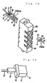
- FIG. 14 As a means for connecting such optical fibers to each other, as shown in FIG. 14, a method has been proposed, in which, using an adapter 35 having a plurality of optical connector insertion holes 36, optical connectors 10 are inserted from both directions of the optical connector insertion holes 36 and connected to each other.
- the proposed method there is one which is disclosed in an extract B-10-34 of the 1997 Transmission Society Meeting of the Electronic Information Transmission Society.
- an optical connector housing 3 is provided at the optical connector 10 at one side (the left side of the drawing) of the optical connectors to be connected, thereby constituting an optical connector 10(10a) having an optical connector housing 3.
- the optical connector 10a and another optical connector 10b (the right side in the drawing) not provided with the optical connector housing 3 are connected to each other in an optical connector insertion hole 36, utilizing the optical connector housing 3.
- the optical connector housing 3 has arm portions 1 each extending from both side ends of the face (base end face) 2 at the base side, and the space put between the arm portions 1 is constituted as accommodation space of the ferrule 6 of the optical connector 10.
- a claw portion 4 is formed at the tip end side of the respective arm portions 1, and the respective tip ends of the arm portions 1 are constituted as a wedge-like latch structure.
- a spring 5 is provided so as to extend from the rear end face 18 of the ferrule 6 to the face at the base end side of the optical connector housing 3.
- the spring 5 presses the ferrule 6 of the optical connector 10a against the optical connector 10 being an object to which the ferrule 6 is connected.
- the respective tip ends of the arm portions 1 of the optical connector housing 3 is provided so as to extend beyond the connection end face 21 of the ferrule 6 outwardly.
- the claw portions 4 at the tip ends of the arm portions 1 are caught by the flange portion 19 of the optical connector 10b illustrated at the right side in the drawing, whereby the optical connectors 10 are coupled to each other.
- the optical connector 10 When attaching and detaching the optical connector 10, that is, connecting and disconnecting the optical connectors 10, a specified tool or fixture exclusively used for connection and disconnection is used. For example, when the optical connectors 10 are connected to each other, the right side optical connector 10b held by the fixture is pressed into the optical connector housing 3 and is connected to the left side optical connector 10a. Also, when disconnecting the optical connectors 10 from each other, the claw portions 4 of the left side optical connector 10a, which is caught by the flange portion 19 of the right side optical connector 10b, is removed by a wedge, and the optical connector 10b is pulled out, whereby the optical connectors 10a and 10b are disconnected from each other.
- the optical connectors 10 connected to each other are caused to overlap each other in the vertical direction of the drawing and they are disposed and accommodated.
- an exclusive attaching and detaching tool is required to connect the optical connectors 10 to each other and to disconnect the same from each other.
- Such an attaching and detaching tool will be used less in line with advances in high integrated optical connectors.
- optical connectors disposed at a high integration density are detachably connected to each other, and optical connectors are detachably connected to an optical module mounted on a substrate at a high integration density, it was difficult to connect the optical connectors to each other and to disconnect the same from each other, using the proposed method for connecting optical connectors.
- the present invention was developed in view of the above problems, and it is therefore a first object of the invention to provide an optical connector housing which enables easy attachment and detachment of optical connectors without any need for any exclusive attachment and detachment tool, and an optical connector using the optical connector housing.
- an optical connector housing which is provided with arm portions extending from both end sides of the face at the base end side, space put between said arm portions is constituted as the accommodation space of a ferrule of said optical connector, comprises an engaging portion formed so as to be engaged with an object to be connected, at the tip end side of said respective arm portions, and an angle widening drive cam face, which can open the clearance between the arm portions when said ferrule is drawn near the face side of said base end side, protruding from and formed at the inner wall of said arm portions, extending from the position of the rear end face of said ferrule to be accommodated in said accommodation space to the base end side of an optical connector housing.
- a first aspect of an optical connector according to the invention is featured in that it is provided with an optical connector housing thus constructed above, a ferrule is accommodated in the ferrule accommodation space of said optical connector housing, and a resilient member, which presses said ferrule against an object to be connected, secured so as to extend from the rear end face of said ferrule to the face at the base end side of the optical connector housing.
- a second aspect of an optical connector according to the invention is featured in that, in addition to the first aspect of the optical connector according to the invention, the tip end portions of the arm portions of an optical connector housing extend beyond the connection end face of said ferrule.
- a third aspect of an optical connector according to the invention is featured in that, in addition to the first or second aspect of the optical connector according to the invention, an optical fiber protection housing is provided so that an optical fiber ribbon led out from the rear end side of a ferrule accommodated in the ferrule accommodation space of an optical connector housing is placed between both the sides thereof, or so that the outer circumferential surface thereof is covered, said optical fiber protection housing is provided in said optical connector housing in a state where it does not come out, and in a state where it can advance and retract in the extending direction of the arm portions of said optical connector housing, and a cam surface contacting portion which, when pulling said optical fiber protection housing rearwards, is brought into contact with the surface of an angle widening drive cam of the arm portions of said optical connector housing and drives so as to open the optical connector housing is formed in said optical fiber protection housing so as to protrude toward said arm portion side.
- a fourth aspect of an optical connector of the invention is featured in that, in addition to the third aspect of the invention, a ferrule stopping portion to be engaged with a flange portion or in a recess portion formed at the ferrule is provided in the optical fiber protection housing.
- a first aspect of a connection structure between an optical connector and an optical component according to the invention is featured in that, by an engaging portion of an optical connector in the first or second construction of the optical connector according to the invention with a portion to be engaged of an optical component being an object to be connected, said optical connector is connected to said optical component being an object to be connected, wherein when a ferrule is drawn near the rear end side of the arm portion against a pressing force of a resilient member, the rear end side of the ferrule moves along the surface of the angle widening drive cam to cause the arm portions to be widened and said engaging portion is disengaged from said portion to be engaged, whereby the connection between the optical connector and said optical component being an object to be connected is released.
- a second aspect of a connection structure between an optical connector and an optical component according to the invention is featured in that, by engaging an engaging portion of an optical connector in the third or fourth aspect of the optical connector according to the invention with a portion to be engaged of an optical component to be connected, said connector is connected to the optical component being an object to be connected, wherein when an optical fiber protection housing is drawn toward the rear end side thereof, the cam surface contacting portion of the optical fiber protection housing moves along the surface of an angle widening drive cam to cause the arm portions to be widened, and wherein when said engaging portion is disengaged from said portion to be engaged, the connection between the optical connector and the optical component being an object to be connected is released.
- a third aspect of a connection structure between an optical connector and an optical component according to the invention is featured in that, in addition to the first or second aspect of the connection structure between an optical connector and an optical component according to the invention, a plurality of optical fibers are disposed in parallel in a ferrule of the optical connector, and optical components being objects to be connected are arrayed and formed on a substrate in an erect state in the form of an array along the surface of said substrate, wherein by an engaging portion of an optical connector housing being engaged with a portion to be engaged of an optical component being an object to be connected, said optical components being objects to be connected and said optical connector are detachably connected to each other so that a plurality of optical fibers of said respective optical connector are arrayed in a perpendicular direction with respect to the surface of said substrate.
- a fourth aspect of a connection structure between an optical connector and an optical component according to the invention is featured in that, in addition to the first or second aspect of the connection structure between an optical connector and an optical component according to the invention, a plurality of optical fibers are disposed in parallel in a ferrule of an optical connector, section guiding walls are arrayed and formed on a substrate in an erect state in the form of an array along the surface of said substrate, optical components being objects to be connected are disposed in an erect state between the respective section guiding walls, and the tip end sides of the respective section guiding walls protrude forwards from the connection end faces of optical components being objects to be connected, so that they become an optical connector insertion guide, wherein said optical connectors are guided by and inserted into said optical connector insertion guide, and by an engaging portion of the optical connector housing being engaged with a portion to be engaged of the optical components being objects to be connected, said respective optical components being objects to be connected are detachably connected to said optical connector.
- arm portions extend from both end sides of the face at the base end side of an optical connector housing, and a ferrule of the optical connector is accommodated in an accommodation space of the optical connector placed between the arm portions.
- an engaging portion engaged with an object to be connected is formed at the tip end side of the respective arm portions. Therefore, for example, by pressing the optical connector housing to the objects to be connected, and engaging the engaging portion with a portion to be engaged of the object to be connected such as, for example, an optical module, the optical connector can be connected to an optical component being an object to be connected.
- the surface of an angle widening drive cam is formed to protrude on the inner wall of the arm portions from the position of the rear end face of a ferrule accommodated in the accommodation space, to the base end side of the optical connector housing. Therefore, when the ferrule is drawn to the face side of the base end side of the optical connector housing, the tip ends of the arm portions of the optical connector housing are widened by actions of the surface of the angle widening drive cam (by the rear end face of the ferrule being drawn to the base end side of the optical connector housing along the surface of the angle widening drive cam). Therefore, the engaging portion of the optical connector housing is disengaged from the portion to be engaged, at the side of objects being connected, whereby the optical connector is disconnected from the objects to be connected.
- an optical fiber protection housing is provided in a ferrule accommodation space of the optical connector housing
- the cam surface contacting portion of the optical fiber protection housing moves along the surface of the angle widening drive cam to cause the tip ends of the arm portions to be widened as the arm portions are widened. Therefore, the engaging portion of the optical connector housing is disengaged from the portion to be engaged at the side of objects to be connected, whereby the optical connector is disconnected from the objects to be connected.
- the optical connector can be easily connected to or disconnected from objects to be connected, without the use of any special connection tool.
- an optical connector housing, an optical connector, and a connection structure between the optical connector and optical components according to the invention it is possible to very easily detachably connect optical connectors to objects to be connected, without the use of any special connection tool. Furthermore, the construction of the optical connector housing and optical connectors is very simple. Therefore, it is possible to array optical connectors and objects to be connected such as optical modules, etc., at a high integration density.
- a plurality of optical modules are arrayed on a substrate in an erect state in the form of an array along said substrate.
- optical connectors of the respective constructions are detachably connected to the respective optical modules, optical connectors and optical modules can be disposed at a yet higher integration density, whereby a plurality of optical fibers arrayed in an optical connector can be disposed at a higher integration density.
- an optical connector constructed so that an optical fiber protection housing is provided in a ferrule accommodation space of the optical connector housing, when disconnecting the optical connector from an object to be connected, the optical fiber ribbon leading from the rear end side of the ferrule of the optical connector is not pulled, but as shown above, the optical fiber protection housing is pulled rearward, whereby the tip ends of the arm portions of the optical connector housing are widened, and the optical connector is disconnected from the object to be connected.
- the connection of the optical connector is released not by pulling the optical fiber ribbon but pulling the optical fiber protection housing, a fear that the optical fibers may be damaged can be completely prevented when disconnecting the optical connector.
- the optical fiber protection housing and ferrule are made integral with each other. Therefore, when pulling the optical fiber protection housing rearward, the ferrule can pulled rearward at the same time. Accordingly, when releasing the engaged optical connector, the connection between the ferrule and objects to be connected can be carried out at the same time.
- section guiding walls are arrayed and formed on a substrate in an erect state in the form of an array along the surface of the substrate, and optical components being objects to be connected are arrayed in an erect state between respective section guiding walls. Since the tip end side of the respective section guiding walls can be used as an optical connector insertion guide, connection between the optical connector and optical components being objects to be connected can be further easily carried out.
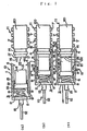
- FIG. 1(a) an example of a connection structure between an optical connector and optical components, which is the first preferred embodiment of the connection structure between the optical connector using an optical connector housing according to the invention and optical components, is illustrated in the form of a plan view.
- an optical connector housing 3 is provided with arm portions 1 each extending from both end sides of the face 2 at the base end side and is formed channel-like. Space placed between the above respective arm portions 1 constitutes an accommodation space in a ferrule 6 of an optical connector 6. Claws 4 acting as engaging portions which are engaged with objects to be connected (in the first preferred embodiment, optical module 11) are formed at the tip end side of the respective arm portions 1.
- the ferrule 6, optical fiber ribbon 12 and boot 13 are formed as in the prior art examples.
- a characteristic point of the optical connector housing according to the first preferred embodiment resides in that the surface 9 of an angle widening drive cam protrudes from and is formed on the inner walls of the arm portions 1 extending from the position of the rear end face 18 of the ferrule accommodated in the abovementioned accommodation space to the base end side of the optical connector housing 3.
- a protrusion portion 8 is formed on both the inner walls of the arm portions 1, and the surface 9 of the angle-widening drive cam is in the form of a tapered surface at the side opposed to the rear end face 18 of the ferrule, which is formed at the protrusion portions 8.
- the surface 9 of the angle widening drive cam is to widen the arm portions 1 when the ferrule 6 is drawn to the side of the face 2 at the base end side.
- a spring 5 is provided so as to extend from the rear end face 18 of the ferrule 6 to the face 2 at the base end side of the optical connector housing 3.
- the spring 5 functions as a resilient body which presses the ferrule 6 to the objects to be connected.
- the tip end of the arm portions 1 of the optical connector housing 3 extends forward of the connection end face of the ferrule 6.
- a stopper 15 protrudes from the inner wall of the arm portions 1 at the central portion thereof. The stopper 15 stops a flange portion 19 in engagement with each other, whereby the ferrule 6 is prevented from coming off from the optical connector housing 3.
- an optical module 11 connected to the optical connector 10 has an MT ferrule type package 20.
- the package 20 has a plurality of lead terminals 7 provided at both sides thereof, in order to mount, for example, the module 11 on a substrate.
- the optical module 11 is provided with a recess 14 as a portion to be engaged, with which the claw portions at the tip end of the optical connector housing 3 are engaged.
- a pair of guide pin holes 17 are formed on the connection end face 22 of the optical module 11, and as shown in FIG. 11(a), guide pins 16 for connection with the optical connector 10 are, respectively, inserted into the guide pin holes 17.
- connection structure when connecting the optical connector 10 with the optical module 11, for example, they press the optical connector 10 into the optical module 11 side holding the optical connector housing 3, and as shown in FIG. 1(b), the claw portions 4 of the optical connector 10 are engaged with the recess 14 of the optical module 11, whereby connection between the optical connector 10 and the optical module 11 is carried out.
- work of drawing the ferrule 6 of the optical connector 6 to the rear end side of the arm portions 1 may be carried out by holding the ferrule 6 directly, by pulling the optical fiber tape ribbon 12, or by pulling the boot 13.
- the optical connector housing 3 is formed channel-like and it can directly touch both the upper and lower sides of the ferrule 6. Therefore, when disconnecting the optical connector 10, by drawing the corresponding ferrule 6 with the ferrule held directly, it is possible to very easily carry out disconnection of the optical connector.
- the claw portion 4 is provided at the tip end side of the arm portions 1 of the optical connector housing 3 of the optical connector 10, and the recess 14, which is engaged with the claw portion 4 is provided at the optical module being an object to be connected. Therefore, by only engaging the claw portion 4 of the optical connector 10 in the recess 4 of the optical module 11, the optical connector 10 can be connected to the optical module 11.
- the optical connector 10 can be disconnected from the optical module by only drawing the ferrule 6 of the optical connector 10 to the base end side of the optical connector housing 3.
- the optical connector 10 and optical module 11 can be detachably connected very easily, it is possible to array and dispose the optical connector 10 and optical module 11 at a high integration density. Based thereon, a still higher integration density mounting can be provided. Furthermore, in the first preferred embodiment, the construction of the optical connector housing 3 and optical connector 10 is very simple. Therefore, components connecting between the optical connector 10 and optical module 11 can be disposed at a high integration density surely, and since it is possible to very easily produce the optical connector 10 and optical connection housing 3, production cost thereof can be further reduced.
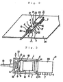
- FIG. 2 one example of a connection structure between an optical module 11 and an optical connector 10, to which the first embodiment is applied, is illustrated in the form of a perspective view.
- the optical module 11 shown in FIG. 2 is mounted on an electronic circuit substrate 24.
- FIG. 3 shows an example of the structure, further showing a connected state where the second preferred embodiment of a connection structure between an optical connector using an optical connector housing according to the invention and an optical component connects an optical connector to an optical module. Also, in the description of the second preferred embodiment, parts which are identical to those in the first preferred embodiment are given the same reference numbers, and overlapping description of the common components is omitted.
- a characteristic point at which the connection structure between the optical connector 10 and optical module 11 according to the second embodiment differs from that in the first preferred embodiment resides in that the optical module 11 is constructed so as to have lead terminals 7 at only one side of the package 20, and the optical connector 10 is connected to such an optical module. All the others remain the same as those in the first preferred embodiment.
- the optical module 11 is mounted on a substrate in an erect state, whereby the optical module 11 and optical connector 10 can be mounted at still higher integration density.
- the method for connecting the optical connector 10 to the optical module 11 and disconnecting the former from the latter is similar to that in the first preferred embodiment, wherein the same effects can be brought about.
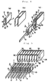
- an optical module 11 shown in FIG. 4(a) may be guided by section guiding walls 30 shown in FIG. 4(b), and disposed and mounted on a substrate 24.
- the tip end side 32 of the section guiding wall 30 protrudes forward from the connection end face 22 of the optical module 11, and the protruding part thereof may function as an optical connector insertion guide.
- the connection end faces of the optical connector 10 and optical module 11 are opposed to each other.
- the optical connector 10 is inserted between the section guiding walls 30 along the optical connector insertion guide of the section guiding walls 30, wherein the claw portion 4 of the optical connector housing 3 of the optical connector 10 is engaged with the recess 14 of the optical module 11. Thereby, the optical connector 10 is connected to the optical module 11. Since an optical connector-insertion guide is provided at the section guiding walls 30, it is possible to further easily and securely connect the optical connector 10 and the optical module 11 to each other.
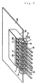
- a connected body consisting of the optical module 11 and optical connector 10 at a high integration density. That is, a plurality of section guiding walls 30 are arrayed and disposed on a substrate 24 in an erect state in the form of an array along the substrate surface, and the section guiding walls 30 are supported by a guide supporting portion 31. Optical modules 11 are, respectively, disposed between these section guiding walls 30 in an erect state, and optical connectors 10 are, respectively, connected to the respective optical modules 11, whereby a connected body consisting of the optical modules 11 and optical connectors 10 can be disposed at a higher integration density.
- the tip end sides 2 of the section guiding walls 30 may protrude forward from the connection end face 22 of the respective optical modules 11 and constitute an optical connector insertion guide as in the example shown in FIG. 4.
- the optical connector insertion guide is formed on the section guiding walls 30, it is possible to very easily connect the respective optical modules 11 and optical connector 10 to each other as in the above description.
- the optical modules 11 and optical connectors 10 can be detachably connected to each other without the use of any connection tool, and it is very convenient.
- optical modules can be arrayed in the vertical direction with respect to the reference surface of the substrate 24, it is possible to mount optical fibers at a very high integration density.
- FIG. 6 shows an example, to which a connection structure between an optical connector and optical modules according to the second preferred embodiment is applied, in the form of a perspective view.
- an optical module 10 is connected to the optical modules 11 mounted on an electronic circuit substrate 24, wherein the optical module 11 and optical connector 10 are provided with a unique construction shown in the second preferred embodiment.
- the section guiding walls 30 shown in FIG. 5 are accommodated in a guide package 33.
- the optical modules 11 and optical connector 10 can be detachably connected to each other.
- the optical connector 10 in order to prevent the optical connector 10 from coming off from the optical modules 11 as a result of the optical fiber ribbon 12 being carelessly caught by something, the optical connector 10 is fixed by providing the cover 25.
- the disconnection can be carried out by removing the cover 25 and drawing a desired optical connector 10 to the base end side of the optical connector housing 3.
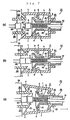
- FIG. 7 a connection structure between an optical connector and a connector being an object to be connected, which is a third preferred embodiment of a connection structure between an optical connector using an optical connector housing and optical components according the present invention, is illustrated in the form of a cross-sectional view.
- FIG. 8 is a disassembled view showing an optical connector shown in the third preferred embodiment along with an optical connector being an object to be connected, in the form of a perspective view. Also, in the description of the third preferred embodiment, parts which are identical to those in the respective preferred embodiments are given the same reference numbers, and overlapping description of the common parts is omitted.
- a characteristic point of the optical connector to which the third preferred embodiment is applied resides in its being constructed so as to prevent an optical fiber ribbon from being damaged when disconnecting the optical connector. That is, as shown in FIG. 7 and FIG. 8, an optical fiber ribbon (in the preferred embodiment fiber tape ribbon 12) is drawn out from the rear end side of the ferrule 6 accommodated in the ferrule accommodation space of the optical connector housing 3.
- a cylindrical optical fiber protection housing 40 is provided in the form that covers the outer circumferential surface of the optical fiber tape ribbon 12. By means of the optical fiber protection housing 40, it becomes possible to disconnect the optical connector 10 without pulling the ferrule 6 and optical fiber tape ribbon 12.
- the ferrule 6 is an MT type in the third preferred embodiment. In FIG. 7 and FIG. 8, illustration of the flange portion 19 shown in FIG. 1 is omitted.
- the optical fiber protection housing 40 is provided with two hole portions 42, and the base end portion of the optical connector housing 3 is inserted into the two hole portions 42 at a suitable interval.
- the optical fiber protection housing 40 is provided so as to advance and retract in the extending direction of the arm portions 1 of the optical connector housing so that it does not come off from the optical connector housing 3.
- the cam surface-contacting portion 41 protrudes from and is formed at the arm portion 1 sides in the optical fiber protection housing 40.
- the cam surface contacting portion 41 is brought into contact with the surface 9 of the angle widening drive cam of the arm portions 1 of the optical connector housing 3 when the optical fiber protection housing 40 is pulled rearwards, and causes the tip end side of the optical connector housing 3 to be widened.
- the cam surface contacting portion 41 is constructed so as to have a tapered surface which is widened toward the tip end side.
- the interval between the hole portion 42 of the optical fiber protection housing 40 and the base end side of the optical connector housing 3 is formed to be an interval, in which, when the optical fiber protection housing 40 is pulled rearwards, the cam surface contacting portion 41 is brought into contact with the surface 9 of the angle widening drive cam of the arm portions 1 of the optical connector housing 3 and the optical connector hosing 3 can be widened.
- a connector being an object to be connected is accommodated in a connector casing 50 fixed at the substrate 24.
- a claw 51 to be engaged with, which acts as a portion to be engaged, is provided at the tip end of the connector casing 50.
- connection structure according to the third preferred embodiment when the optical connector 10 is connected to the connector being an object to be connected, the optical connector 10 is pressed into the ferrule 26 side, for example, holding the optical connector housing 3, in a state as shown in FIG. 7(a) as in the connection structure according to the abovementioned first preferred embodiment, whereby as shown in FIG. 7(b), the claw portion 4 is engaged in the claw 5 to be engaged with of the connector casing 50. If so, the ferrule 6 of the optical connector 10 is connected to the ferrule 26 of the connector being an object to be connected.
- the optical protection housing 40 When disconnecting such a connection structure, as shown in FIG. 7(c), the optical protection housing 40 is pulled rearward, whereby the cam surface contacting portion 41 of the optical fiber protection housing 40 moves along the surface 9 of the angle widening drive cam to widen the arm portions 1, whereby the claw portion 4 is disconnected from the claw 51 to be engaged. Therefore, the connection between the optical connector 10 and the connector being an object to be connected is released.
- the arm portions 1 of the optical connector housing 3 are deformed as shown in FIG. 9 to widen the tip end sides thereof. Also, widening resulting from deformation of the arm portions may be available in the first and second preferred embodiments as well.
- the third preferred embodiment was constructed as described above, the third preferred embodiment can bring about the same effects as those in the respective preferred embodiments.
- the optical connector 10 can be disconnected from the side being connected. Since the third preferred embodiment is constructed as described above, no optical fiber tape ribbon 12 may be directly pulled. For example, if the optical fiber tape ribbon 12 is directly pulled when disconnecting the optical connector 10, there is absolutely no possibility that the optical fiber tape ribbon 12 is damaged.
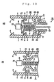
- a protrusion portion 48 for preventing the housing 40 from coming off is provided on the inner wall of the arm portions of the optical connector housing 3 as shown in FIG. 10(a), and the protrusion portion 48 may be inserted into the hole portion 42 of the optical fiber protection housing 40 with a suitable allowance.
- the interval between the hole portion 42 of the optical fiber protection housing 40 and the protrusion portion 48 for preventing the housing 40 from coming off is formed to be an interval in which, when the optical fiber protection housing 40 is pulled rearward, the cam surface contacting portion 41 is brought into contact with the surface 9 of the angle widening drive cam of the arm portions 1 of the optical connector housing 3, and the optical connector housing 3 can be widened.
- the optical fiber protection housing 40 may be constructed in the form as shown in FIG. 10(b). That is, in the example of an optical fiber protection housing 40 shown in FIG. 10(b), a constriction portion 49 is provided at the opposed portions of the optical fiber protection housing 40 with respect to the surface 9 of the angle widening drive cam of the optical connector housing 3.
- the optical fiber protection housing 40 may be constructed in the respective forms shown in FIG.11(a) and (b). That is, in the example of the optical fiber protection housing 40 shown in FIG. 11(a) and (b), a ferrule holding portion 43 is provided, which is engaged with a flange portion 19 or engaged in a recess 28, either of which is formed on the ferrule 6. If constructed so, when the optical fiber protection housing 40 is pulled rearward, the ferrule 6 can be pulled rearward along with the optical fiber protection housing 40.
- a recess 44 may be provided, as shown in FIG. 11(c), instead of the hole portions 42 of the optical fiber protection housing 40 applied to the third preferred embodiment.
- optical fiber protection housing 40 which is applied to the third preferred embodiment is provided in the form such that the outer circumferential side of the optical fiber tape ribbon 12 drawn out from the rear end side of the ferrule 6 can be covered with, it may be provided in the form such that the optical fiber tape ribbon 12 is sandwiched from both its sides.
- the section guiding walls 30 are not necessarily provided.
- optical modules 11 may be disposed and arrayed on the surface of a substrate 24 in an erect state in the form of an array along the substrate surface without providing any section guiding wall 30.
- the claw 4 of the optical connector housing 3 being engaged in the recess 14 of the respective optical modules 11, a plurality of optical fibers of the respective optical connector 10 will be arrayed in the vertical direction with respect to the substrate surface.
- the connection of the optical connector 10 to optical modules 11 can be further easily carried out.
- connection structure between an optical connector and optical components according to the invention is applied to a plurality of connections between the optical components and the optical connector
- the optical components disposed on a substrate in an erect state are not necessarily connected to the optical connector 10.
- they may be connected in the form such that optical fibers arrayed in the ferrule 6 of the optical connector 10 or ferrule of the connector being an object to be connected are placed in parallel along the substrate 24.
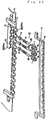
- connection structure shown in FIG. 13 is shown in a disassembled state, using an image view in which the connection structure shown in FIG. 7 and FIG. 8 is applied to a connection between optical connectors and a plurality of connectors being objects to be connected, which are placed on the substrate 24 in parallel.
- FIG. 13 by assembling the upper part 50a of the connector casing to the lower part 50b thereof, a connector casing shown in FIG. 8 can be formed.
- a ferrule (not illustrated) secured in the connector casing 50 is connected to the ferrule 6 of the optical connector 10.
- the engaging portion is not necessarily the claw 4.
- a recess 14 is provided at the optical modules 14 as a portion to be engaged, which is engaged in the engaging portion, and in the third preferred embodiment, a claw 51 to be engaged is provided in the connector casing 50.
- the portion to be engaged is not necessary the recess 14 or the claw 51 to be engaged.
- the tip end of the arm portions 1 of the optical connector housing 3 extends forward from the connection end face 21 of the ferrule 6
- the tip end of the arm portions 1 of the optical connector housing 3 may be provided rearward from the connection end face 21 in the case where the position of the portion to be engaged at the object side to be connected extends midway of the ferrule 6 or at the rear end side.
- extending the tip end of the arm portions 1 forward from the connection end face 21 of the ferrule 6 provides a better connection between the optical connector 10 and objects to be connected.
- an optical connector according to the invention is not necessarily connected to optical modules and a connector at the side of objects to be connected, but optical components being objects to be connected to the optical connector may be adequately set.
- the optical connector applied to the invention does not necessarily have an MT type ferrule.
- it may be of such a type in which the ferrule 6 is provided with an optical fiber protection portion 47.
- the spring 5 may be provided on the outer circumferential side of the optical fiber protection portion 47.
- it is constructed such that, when pulling the ferrule 6 rearwards, the tapered portion 46 of the ferrule 6 is brought into contact with the surface 9 of the angle widening drive cam formed at the arm portions 1 of the optical connector housing 3 and moves along the surface 9 of the corresponding angle widening drive cam.
- the tapered portion 46 of the corresponding ferrule 6 moving along the surface 9 of the angle widening drive cam, the arm portions 1 are widened, thereby enabling disconnection of the optical connector 10 from optical components being objects to be connected.
- ferrule 6 of an optical connector applied to the invention may be a single-fiber cylindrical ferrule.
- a sleeve may be used as in the prior arts.
- the invention relates to an optical connector housing by which connection of an optical connector to objects to be connected, and disconnection of the optical connector from the objects can be easily carried out, an optical connector using the same optical connector housing, and a connection structure between an optical connector using the same optical connector housing and optical components, whereby the invention is very applicable to cases where an optical connector is connected to optical components at a high integration density.
Landscapes
- Physics & Mathematics (AREA)
- General Physics & Mathematics (AREA)
- Optics & Photonics (AREA)
- Mechanical Coupling Of Light Guides (AREA)
Abstract
An optical connector housing (3) having arm portions (1)
extending from both end sides of the face (2) of the base end
side, and a ferrule (6) is accommodated in space placed between
the arm portions (1). When the claws (4) at the tip ends of
the respective arm portions are engaged in a recess (14) of
an optical module (11), an optical connector (10) can be
connected to an optical module (11). A surface (9) of an angle
widening drive cam is provided on the inner walls of the arm
portions (1) extending from a position at the rear end face
(18) of the ferrule (6) to the base end side of the optical
connector housing (3). When the ferrule (6) is drawn to the
face (2) side of the base end side, the rear end face (18) of
the ferrule (6) moves along the surface (9) of the angle
widening drive cam to cause the arm portions (1) to be widened,
whereby the claws (4) are disengaged from the recess (14) and
the optical connector (10) can be disconnected from the optical
module (11). Highly integrated mounting of optical connectors
can be achieved without the use of any connecting tool, by which
the optical connectors can be detachably connected to optical
components being objects to be connected.
Description
The present invention relates to an optical connector
housing used for detachably connecting an optical connector
mainly employed in optical transmissions and an optical
component, an optical connector using the same optical
connector housing, and a structure for connecting between an
optical connector using the optical connector housing and an
optical component.
Recently, optical transmissions using optical fibers have
been frequently employed, wherein high bit rate mounting of
optical fibers is demanded. To meet the requirements of high
bit rate mounting of optical fibers, studies and research have
been carried out with respect to downsizing of optical
connectors used to connect optical fibers and high bit rate
mounting of optical modules, etc.
An MU type connector is one-fourth the size in cross-sectional
area in comparison to the conventional SC type
connectors. Further, recently, an MT type optical connector
has been widely utilized, in which multiple optical fibers are
disposed and fixed.
As shown in FIG. 15, this type of MT optical connector is
formed so that an optical fiber tape ribbon 12 in which a
plurality of optical fibers are disposed in parallel are
inserted in a ferrule 6. In the drawing, 13 indicates a boot
which protect the optical fiber tape ribbon 12, and 19 indicates
a flange portion of the ferrule 6. A plurality of optical fiber
insertion holes (not illustrated) are formed in the ferrule
6. Respective optical fibers of the optical fiber tape ribbon
12 are inserted into these respective optical fiber insertion
holes while the tip ends of these optical fibers are exposed
to the connection end face 21 of the ferrule 6.
As a means for connecting such optical fibers to each other,
as shown in FIG. 14, a method has been proposed, in which, using
an adapter 35 having a plurality of optical connector insertion
holes 36, optical connectors 10 are inserted from both
directions of the optical connector insertion holes 36 and
connected to each other. As the proposed method, there is one
which is disclosed in an extract B-10-34 of the 1997
Transmission Society Meeting of the Electronic Information
Transmission Society.
In the proposed method, an optical connector housing
3 is provided at the optical connector 10 at one side (the left
side of the drawing) of the optical connectors to be connected,
thereby constituting an optical connector 10(10a) having an
optical connector housing 3. The optical connector 10a and
another optical connector 10b (the right side in the drawing)
not provided with the optical connector housing 3 are connected
to each other in an optical connector insertion hole 36,
utilizing the optical connector housing 3. The optical
connector housing 3 has arm portions 1 each extending from both
side ends of the face (base end face) 2 at the base side, and
the space put between the arm portions 1 is constituted as
accommodation space of the ferrule 6 of the optical connector
10. A claw portion 4 is formed at the tip end side of the
respective arm portions 1, and the respective tip ends of the
arm portions 1 are constituted as a wedge-like latch structure.
In the optical connector 10a provided with the optical
connector housing 3, a spring 5 is provided so as to extend
from the rear end face 18 of the ferrule 6 to the face at the
base end side of the optical connector housing 3. The spring
5 presses the ferrule 6 of the optical connector 10a against
the optical connector 10 being an object to which the ferrule
6 is connected. The respective tip ends of the arm portions
1 of the optical connector housing 3 is provided so as to extend
beyond the connection end face 21 of the ferrule 6 outwardly.
The claw portions 4 at the tip ends of the arm portions 1 are
caught by the flange portion 19 of the optical connector 10b
illustrated at the right side in the drawing, whereby the
optical connectors 10 are coupled to each other.
When attaching and detaching the optical connector 10, that
is, connecting and disconnecting the optical connectors 10,
a specified tool or fixture exclusively used for connection
and disconnection is used. For example, when the optical
connectors 10 are connected to each other, the right side
optical connector 10b held by the fixture is pressed into the
optical connector housing 3 and is connected to the left side
optical connector 10a. Also, when disconnecting the optical
connectors 10 from each other, the claw portions 4 of the left
side optical connector 10a, which is caught by the flange
portion 19 of the right side optical connector 10b, is removed
by a wedge, and the optical connector 10b is pulled out, whereby
the optical connectors 10a and 10b are disconnected from each
other. In the case where the respective optical connectors 10
are inserted into the respective optical connector insertion
holes 36, and connection of the optical connectors 10 is
completed, the optical connectors 10 connected to each other
are caused to overlap each other in the vertical direction of
the drawing and they are disposed and accommodated.
However, as described, an exclusive attaching and
detaching tool is required to connect the optical connectors
10 to each other and to disconnect the same from each other.
Such an attaching and detaching tool will be used less in line
with advances in high integrated optical connectors. Also, in
the case where the optical connectors are connected to and
disconnected from each other by utilizing such an attaching
and detaching tool, a problem arises, by which the attaching
and detaching management of optical connectors becomes
cumbersome. Therefore, in the case where the optical connectors
disposed at a high integration density are detachably connected
to each other, and optical connectors are detachably connected
to an optical module mounted on a substrate at a high
integration density, it was difficult to connect the optical
connectors to each other and to disconnect the same from each
other, using the proposed method for connecting optical
connectors.
The present invention was developed in view of the above
problems, and it is therefore a first object of the invention
to provide an optical connector housing which enables easy
attachment and detachment of optical connectors without any
need for any exclusive attachment and detachment tool, and an
optical connector using the optical connector housing. In
addition, it is a second object of the invention to provide
an optical connector using an optical connector housing by
which an optical connector can be detachably connected to an
optical component such as an optical module at a high
integration density, and a connection structure between the
optical connector and an optical component.
In order to achieve the abovementioned objects, the
invention is constructed so as to have the following means in
order to solve the problems. That is, an optical connector
housing according to the invention, which is provided with arm
portions extending from both end sides of the face at the base
end side, space put between said arm portions is constituted
as the accommodation space of a ferrule of said optical
connector, comprises an engaging portion formed so as to be
engaged with an object to be connected, at the tip end side
of said respective arm portions, and an angle widening drive
cam face, which can open the clearance between the arm portions
when said ferrule is drawn near the face side of said base end
side, protruding from and formed at the inner wall of said arm
portions, extending from the position of the rear end face of
said ferrule to be accommodated in said accommodation space
to the base end side of an optical connector housing.
A first aspect of an optical connector according to the
invention is featured in that it is provided with an optical
connector housing thus constructed above, a ferrule is
accommodated in the ferrule accommodation space of said optical
connector housing, and a resilient member, which presses said
ferrule against an object to be connected, secured so as to
extend from the rear end face of said ferrule to the face at
the base end side of the optical connector housing.
Further, a second aspect of an optical connector according
to the invention is featured in that, in addition to the first
aspect of the optical connector according to the invention,
the tip end portions of the arm portions of an optical connector
housing extend beyond the connection end face of said ferrule.
A third aspect of an optical connector according to the
invention is featured in that, in addition to the first or
second aspect of the optical connector according to the
invention, an optical fiber protection housing is provided so
that an optical fiber ribbon led out from the rear end side
of a ferrule accommodated in the ferrule accommodation space
of an optical connector housing is placed between both the sides
thereof, or so that the outer circumferential surface thereof
is covered, said optical fiber protection housing is provided
in said optical connector housing in a state where it does not
come out, and in a state where it can advance and retract in
the extending direction of the arm portions of said optical
connector housing, and a cam surface contacting portion which,
when pulling said optical fiber protection housing rearwards,
is brought into contact with the surface of an angle widening
drive cam of the arm portions of said optical connector housing
and drives so as to open the optical connector housing is formed
in said optical fiber protection housing so as to protrude
toward said arm portion side.
In addition, a fourth aspect of an optical connector of
the invention is featured in that, in addition to the third
aspect of the invention, a ferrule stopping portion to be
engaged with a flange portion or in a recess portion formed
at the ferrule is provided in the optical fiber protection
housing.
Still further, a first aspect of a connection structure
between an optical connector and an optical component according
to the invention is featured in that, by an engaging portion
of an optical connector in the first or second construction
of the optical connector according to the invention with a
portion to be engaged of an optical component being an object
to be connected, said optical connector is connected to said
optical component being an object to be connected, wherein when
a ferrule is drawn near the rear end side of the arm portion
against a pressing force of a resilient member, the rear end
side of the ferrule moves along the surface of the angle
widening drive cam to cause the arm portions to be widened and
said engaging portion is disengaged from said portion to be
engaged, whereby the connection between the optical connector
and said optical component being an object to be connected is
released.
Also, a second aspect of a connection structure between
an optical connector and an optical component according to the
invention is featured in that, by engaging an engaging portion
of an optical connector in the third or fourth aspect of the
optical connector according to the invention with a portion
to be engaged of an optical component to be connected, said
connector is connected to the optical component being an object
to be connected, wherein when an optical fiber protection
housing is drawn toward the rear end side thereof, the cam
surface contacting portion of the optical fiber protection
housing moves along the surface of an angle widening drive cam
to cause the arm portions to be widened, and wherein when said
engaging portion is disengaged from said portion to be engaged,
the connection between the optical connector and the optical
component being an object to be connected is released.
A third aspect of a connection structure between an optical
connector and an optical component according to the invention
is featured in that, in addition to the first or second aspect
of the connection structure between an optical connector and
an optical component according to the invention, a plurality
of optical fibers are disposed in parallel in a ferrule of the
optical connector, and optical components being objects to be
connected are arrayed and formed on a substrate in an erect
state in the form of an array along the surface of said substrate,
wherein by an engaging portion of an optical connector housing
being engaged with a portion to be engaged of an optical
component being an object to be connected, said optical
components being objects to be connected and said optical
connector are detachably connected to each other so that a
plurality of optical fibers of said respective optical
connector are arrayed in a perpendicular direction with respect
to the surface of said substrate.
Further, a fourth aspect of a connection structure between
an optical connector and an optical component according to the
invention is featured in that, in addition to the first or
second aspect of the connection structure between an optical
connector and an optical component according to the invention,
a plurality of optical fibers are disposed in parallel in a
ferrule of an optical connector, section guiding walls are
arrayed and formed on a substrate in an erect state in the form
of an array along the surface of said substrate, optical
components being objects to be connected are disposed in an
erect state between the respective section guiding walls, and
the tip end sides of the respective section guiding walls
protrude forwards from the connection end faces of optical
components being objects to be connected, so that they become
an optical connector insertion guide, wherein said optical
connectors are guided by and inserted into said optical
connector insertion guide, and by an engaging portion of the
optical connector housing being engaged with a portion to be
engaged of the optical components being objects to be connected,
said respective optical components being objects to be
connected are detachably connected to said optical connector.
In the invention thus constructed, arm portions extend from
both end sides of the face at the base end side of an optical
connector housing, and a ferrule of the optical connector is
accommodated in an accommodation space of the optical connector
placed between the arm portions. In the optical connector
housing, an engaging portion engaged with an object to be
connected is formed at the tip end side of the respective arm
portions. Therefore, for example, by pressing the optical
connector housing to the objects to be connected, and engaging
the engaging portion with a portion to be engaged of the object
to be connected such as, for example, an optical module, the
optical connector can be connected to an optical component
being an object to be connected.
Also, in the optical connector housing, the surface of an
angle widening drive cam is formed to protrude on the inner
wall of the arm portions from the position of the rear end face
of a ferrule accommodated in the accommodation space, to the
base end side of the optical connector housing. Therefore, when
the ferrule is drawn to the face side of the base end side of
the optical connector housing, the tip ends of the arm portions
of the optical connector housing are widened by actions of the
surface of the angle widening drive cam (by the rear end face
of the ferrule being drawn to the base end side of the optical
connector housing along the surface of the angle widening drive
cam). Therefore, the engaging portion of the optical connector
housing is disengaged from the portion to be engaged, at the
side of objects being connected, whereby the optical connector
is disconnected from the objects to be connected.
In addition, in such a construction that an optical fiber
protection housing is provided in a ferrule accommodation space
of the optical connector housing, when the optical fiber
protection housing is pulled rearward, the cam surface
contacting portion of the optical fiber protection housing
moves along the surface of the angle widening drive cam to cause
the tip ends of the arm portions to be widened as the arm
portions are widened. Therefore, the engaging portion of the
optical connector housing is disengaged from the portion to
be engaged at the side of objects to be connected, whereby the
optical connector is disconnected from the objects to be
connected.
As described above, in the invention, by only engaging the
engaging portion at the tip end of the arm portions of the
optical connector housing with the portion to be engaged at
the side of objects to be connected, it is possible to very
easily connect an optical connector to objects to be connected.
Besides, when disconnecting them from each other, by only
drawing the ferrule of the optical connector to the base end
side of the optical connector housing or pulling the optical
fiber protection housing rearwards, it is possible to very
easily disconnect the optical connector from the objects to
be connected. Thus, in the invention, the optical connector
can be easily connected to or disconnected from objects to be
connected, without the use of any special connection tool.
As described above, according to an optical connector
housing, an optical connector, and a connection structure
between the optical connector and optical components according
to the invention, it is possible to very easily detachably
connect optical connectors to objects to be connected, without
the use of any special connection tool. Furthermore, the
construction of the optical connector housing and optical
connectors is very simple. Therefore, it is possible to array
optical connectors and objects to be connected such as optical
modules, etc., at a high integration density.
In particular, for example, as in the third and fourth
constructions of a connection structure between optical
connectors and optical modules according to the invention, a
plurality of optical modules are arrayed on a substrate in an
erect state in the form of an array along said substrate. And,
if optical connectors of the respective constructions are
detachably connected to the respective optical modules,
optical connectors and optical modules can be disposed at a
yet higher integration density, whereby a plurality of optical
fibers arrayed in an optical connector can be disposed at a
higher integration density.
In an optical connector constructed so that an optical
fiber protection housing is provided in a ferrule accommodation
space of the optical connector housing, when disconnecting the
optical connector from an object to be connected, the optical
fiber ribbon leading from the rear end side of the ferrule of
the optical connector is not pulled, but as shown above, the
optical fiber protection housing is pulled rearward, whereby
the tip ends of the arm portions of the optical connector
housing are widened, and the optical connector is disconnected
from the object to be connected. Thus, since the connection
of the optical connector is released not by pulling the optical
fiber ribbon but pulling the optical fiber protection housing,
a fear that the optical fibers may be damaged can be completely
prevented when disconnecting the optical connector.
Still further, in an optical fiber protection housing in
which a ferrule holding portion engaged in a flange portion
or a recess formed in the ferrule, by engaging the ferrule
holding portion of an optical fiber protection housing with
the flange portion of the ferrule or in a recess portion thereof,
the optical fiber protection housing and ferrule are made
integral with each other. Therefore, when pulling the optical
fiber protection housing rearward, the ferrule can pulled
rearward at the same time. Accordingly, when releasing the
engaged optical connector, the connection between the ferrule
and objects to be connected can be carried out at the same time.
Further, according to the fourth construction of a
connection structure between an optical connector and optical
components according to the invention, section guiding walls
are arrayed and formed on a substrate in an erect state in the
form of an array along the surface of the substrate, and optical
components being objects to be connected are arrayed in an erect
state between respective section guiding walls. Since the tip
end side of the respective section guiding walls can be used
as an optical connector insertion guide, connection between
the optical connector and optical components being objects to
be connected can be further easily carried out.
In order to describe the invention in further detail, a
description is given of modes of embodiments of the invention
with reference to the accompanying drawings. Besides, in the
following description of respective embodiments described
below, parts which are identical to those in the prior art
examples are given the same reference numbers, and overlapping
description of the common components is omitted.
In FIG. 1(a), an example of a connection structure between
an optical connector and optical components, which is the first
preferred embodiment of the connection structure between the
optical connector using an optical connector housing according
to the invention and optical components, is illustrated in the
form of a plan view. As shown in FIG. 1(a), in the first
preferred embodiment, an optical connector housing 3 is
provided with arm portions 1 each extending from both end sides
of the face 2 at the base end side and is formed channel-like.
Space placed between the above respective arm portions 1
constitutes an accommodation space in a ferrule 6 of an optical
connector 6. Claws 4 acting as engaging portions which are
engaged with objects to be connected (in the first preferred
embodiment, optical module 11) are formed at the tip end side
of the respective arm portions 1. Also, The ferrule 6, optical
fiber ribbon 12 and boot 13 are formed as in the prior art
examples.
A characteristic point of the optical connector housing
according to the first preferred embodiment resides in that
the surface 9 of an angle widening drive cam protrudes from
and is formed on the inner walls of the arm portions 1 extending
from the position of the rear end face 18 of the ferrule
accommodated in the abovementioned accommodation space to the
base end side of the optical connector housing 3. In the first
preferred embodiment, a protrusion portion 8 is formed on both
the inner walls of the arm portions 1, and the surface 9 of
the angle-widening drive cam is in the form of a tapered surface
at the side opposed to the rear end face 18 of the ferrule,
which is formed at the protrusion portions 8. The surface 9
of the angle widening drive cam is to widen the arm portions
1 when the ferrule 6 is drawn to the side of the face 2 at the
base end side.
As shown in FIG. 1(a), in the optical connector 10, a spring
5 is provided so as to extend from the rear end face 18 of the
ferrule 6 to the face 2 at the base end side of the optical
connector housing 3. The spring 5 functions as a resilient body
which presses the ferrule 6 to the objects to be connected.
Also, the tip end of the arm portions 1 of the optical connector
housing 3 extends forward of the connection end face of the
ferrule 6. In addition, a stopper 15 protrudes from the inner
wall of the arm portions 1 at the central portion thereof. The
stopper 15 stops a flange portion 19 in engagement with each
other, whereby the ferrule 6 is prevented from coming off from
the optical connector housing 3.
Further, an optical module 11 connected to the optical
connector 10 has an MT ferrule type package 20. The package
20 has a plurality of lead terminals 7 provided at both sides
thereof, in order to mount, for example, the module 11 on a
substrate. Also, the optical module 11 is provided with a recess
14 as a portion to be engaged, with which the claw portions
at the tip end of the optical connector housing 3 are engaged.
Also, a pair of guide pin holes 17 are formed on the connection
end face 22 of the optical module 11, and as shown in FIG. 11(a),
guide pins 16 for connection with the optical connector 10 are,
respectively, inserted into the guide pin holes 17.
In the connection structure according to the first
preferred embodiment, when connecting the optical connector
10 with the optical module 11, for example, they press the
optical connector 10 into the optical module 11 side holding
the optical connector housing 3, and as shown in FIG. 1(b),
the claw portions 4 of the optical connector 10 are engaged
with the recess 14 of the optical module 11, whereby connection
between the optical connector 10 and the optical module 11 is
carried out.
Besides, when disconnecting such a state, for example, the
ferrule 6 is pulled to the rear end side of the arm portions
1 against the force of the spring 5, whereby as shown in FIG.
1(c), the rear end portion of the ferrule 6 moves along the
surface 9 of the angle widening drive cam to widen the arm
portions 1, wherein the claw portion 4 is disconnected from
the recess 14, and the connection between the optical connector
10 and the optical module 11 is broken.
Also, work of drawing the ferrule 6 of the optical connector
6 to the rear end side of the arm portions 1 may be carried
out by holding the ferrule 6 directly, by pulling the optical
fiber tape ribbon 12, or by pulling the boot 13. In the first
preferred embodiment, as described above, such a construction
is employed, in which the optical connector housing 3 is formed
channel-like and it can directly touch both the upper and lower
sides of the ferrule 6. Therefore, when disconnecting the
optical connector 10, by drawing the corresponding ferrule 6
with the ferrule held directly, it is possible to very easily
carry out disconnection of the optical connector.
According to the first preferred embodiment, as described
above, the claw portion 4 is provided at the tip end side of
the arm portions 1 of the optical connector housing 3 of the
optical connector 10, and the recess 14, which is engaged with
the claw portion 4 is provided at the optical module being an
object to be connected. Therefore, by only engaging the claw
portion 4 of the optical connector 10 in the recess 4 of the
optical module 11, the optical connector 10 can be connected
to the optical module 11.
Also, since the surface 9 of the angle widening drive cam
is provided on the inner wall surface of the optical connector
housing 3 of the optical connector 10, the optical connector
10 can be disconnected from the optical module by only drawing
the ferrule 6 of the optical connector 10 to the base end side
of the optical connector housing 3.
As described above, in the first preferred embodiment, no
very cumbersome work, in which a special connection tool is
used, is required, and it is possible to very easily connect
the optical connector 10 to the optical module 11 and to
disconnect the former from the latter.
Thus, since the optical connector 10 and optical module
11 can be detachably connected very easily, it is possible to
array and dispose the optical connector 10 and optical module
11 at a high integration density. Based thereon, a still higher
integration density mounting can be provided. Furthermore, in
the first preferred embodiment, the construction of the optical
connector housing 3 and optical connector 10 is very simple.
Therefore, components connecting between the optical
connector 10 and optical module 11 can be disposed at a high
integration density surely, and since it is possible to very
easily produce the optical connector 10 and optical connection
housing 3, production cost thereof can be further reduced.
In FIG. 2, one example of a connection structure between
an optical module 11 and an optical connector 10, to which the
first embodiment is applied, is illustrated in the form of a
perspective view. The optical module 11 shown in FIG. 2 is
mounted on an electronic circuit substrate 24. By applying the
first embodiment to a connection structure between such an
optical module and an optical connector 10, without a
connection tool the optical connector 10 can be very easily,
securely and detachably connected to the optical module mounted
on the electronic substrate 24.
FIG. 3 shows an example of the structure, further showing
a connected state where the second preferred embodiment of a
connection structure between an optical connector using an
optical connector housing according to the invention and an
optical component connects an optical connector to an optical
module. Also, in the description of the second preferred
embodiment, parts which are identical to those in the first
preferred embodiment are given the same reference numbers, and
overlapping description of the common components is omitted.
A characteristic point at which the connection structure
between the optical connector 10 and optical module 11
according to the second embodiment differs from that in the
first preferred embodiment resides in that the optical module
11 is constructed so as to have lead terminals 7 at only one
side of the package 20, and the optical connector 10 is
connected to such an optical module. All the others remain the
same as those in the first preferred embodiment.
In the second preferred embodiment, for example, utilizing
the lead terminals 7 of the optical module 11, the optical
module 11 is mounted on a substrate in an erect state, whereby
the optical module 11 and optical connector 10 can be mounted
at still higher integration density. The method for connecting
the optical connector 10 to the optical module 11 and
disconnecting the former from the latter is similar to that
in the first preferred embodiment, wherein the same effects
can be brought about.
Also, an optical module 11 shown in FIG. 4(a) may be guided
by section guiding walls 30 shown in FIG. 4(b), and disposed
and mounted on a substrate 24. In this case, for example, the
tip end side 32 of the section guiding wall 30 protrudes forward
from the connection end face 22 of the optical module 11, and
the protruding part thereof may function as an optical
connector insertion guide. In such a case, when connecting the
optical connector 10 to the optical module 11, for example,
as shown in FIG. 4(c), the connection end faces of the optical
connector 10 and optical module 11 are opposed to each other.
And, the optical connector 10 is inserted between the section
guiding walls 30 along the optical connector insertion guide
of the section guiding walls 30, wherein the claw portion 4
of the optical connector housing 3 of the optical connector
10 is engaged with the recess 14 of the optical module 11.
Thereby, the optical connector 10 is connected to the optical
module 11. Since an optical connector-insertion guide is
provided at the section guiding walls 30, it is possible to
further easily and securely connect the optical connector 10
and the optical module 11 to each other.
In addition, in the second preferred embodiment, for
example, utilizing an assembled body of such section guiding
walls 30 as shown in FIG. 5, it is possible to dispose a
connected body consisting of the optical module 11 and optical
connector 10 at a high integration density. That is, a plurality
of section guiding walls 30 are arrayed and disposed on a
substrate 24 in an erect state in the form of an array along
the substrate surface, and the section guiding walls 30 are
supported by a guide supporting portion 31. Optical modules
11 are, respectively, disposed between these section guiding
walls 30 in an erect state, and optical connectors 10 are,
respectively, connected to the respective optical modules 11,
whereby a connected body consisting of the optical modules 11
and optical connectors 10 can be disposed at a higher
integration density.
In an example shown in FIG. 5, the tip end sides 2 of the
section guiding walls 30 may protrude forward from the
connection end face 22 of the respective optical modules 11
and constitute an optical connector insertion guide as in the
example shown in FIG. 4. Thus, in the case where the optical
connector insertion guide is formed on the section guiding
walls 30, it is possible to very easily connect the respective
optical modules 11 and optical connector 10 to each other as
in the above description. As a matter of course, as in the
example shown in FIG. 5, in the case where optical connectors
10 are, respectively, connected to a plurality of optical
modules 11, the optical modules 11 and optical connectors 10
can be detachably connected to each other without the use of
any connection tool, and it is very convenient.
In the examples shown in FIG. 4 and FIG. 5, since optical
modules can be arrayed in the vertical direction with respect
to the reference surface of the substrate 24, it is possible
to mount optical fibers at a very high integration density.
FIG. 6 shows an example, to which a connection structure
between an optical connector and optical modules according to
the second preferred embodiment is applied, in the form of a
perspective view. In the example shown in FIG. 6, an optical
module 10 is connected to the optical modules 11 mounted on
an electronic circuit substrate 24, wherein the optical module
11 and optical connector 10 are provided with a unique
construction shown in the second preferred embodiment. Also,
the section guiding walls 30 shown in FIG. 5 are accommodated
in a guide package 33. In the example shown in FIG. 6, the
optical modules 11 and optical connector 10 can be detachably
connected to each other.
In addition, in the example shown in FIG. 6, in order to
prevent the optical connector 10 from coming off from the
optical modules 11 as a result of the optical fiber ribbon 12
being carelessly caught by something, the optical connector
10 is fixed by providing the cover 25. When disconnecting the
optical connector 10 from the optical modules 11, the
disconnection can be carried out by removing the cover 25 and
drawing a desired optical connector 10 to the base end side
of the optical connector housing 3.
In FIG. 7, a connection structure between an optical
connector and a connector being an object to be connected, which
is a third preferred embodiment of a connection structure
between an optical connector using an optical connector housing
and optical components according the present invention, is
illustrated in the form of a cross-sectional view. Further,
FIG. 8 is a disassembled view showing an optical connector shown
in the third preferred embodiment along with an optical
connector being an object to be connected, in the form of a
perspective view. Also, in the description of the third
preferred embodiment, parts which are identical to those in
the respective preferred embodiments are given the same
reference numbers, and overlapping description of the common
parts is omitted.
A characteristic point of the optical connector to which
the third preferred embodiment is applied resides in its being
constructed so as to prevent an optical fiber ribbon from being
damaged when disconnecting the optical connector. That is, as
shown in FIG. 7 and FIG. 8, an optical fiber ribbon (in the
preferred embodiment fiber tape ribbon 12) is drawn out from
the rear end side of the ferrule 6 accommodated in the ferrule
accommodation space of the optical connector housing 3. A
cylindrical optical fiber protection housing 40 is provided
in the form that covers the outer circumferential surface of
the optical fiber tape ribbon 12. By means of the optical fiber
protection housing 40, it becomes possible to disconnect the
optical connector 10 without pulling the ferrule 6 and optical
fiber tape ribbon 12. In addition, the ferrule 6 is an MT type
in the third preferred embodiment. In FIG. 7 and FIG. 8,
illustration of the flange portion 19 shown in FIG. 1 is
omitted.
The optical fiber protection housing 40 is provided with
two hole portions 42, and the base end portion of the optical
connector housing 3 is inserted into the two hole portions 42
at a suitable interval. Thus, in the third preferred embodiment,
the optical fiber protection housing 40 is provided so as to
advance and retract in the extending direction of the arm
portions 1 of the optical connector housing so that it does
not come off from the optical connector housing 3.
Also, the cam surface-contacting portion 41 protrudes from
and is formed at the arm portion 1 sides in the optical fiber
protection housing 40. The cam surface contacting portion 41
is brought into contact with the surface 9 of the angle widening
drive cam of the arm portions 1 of the optical connector housing
3 when the optical fiber protection housing 40 is pulled
rearwards, and causes the tip end side of the optical connector
housing 3 to be widened. In the third preferred embodiment,
the cam surface contacting portion 41 is constructed so as to
have a tapered surface which is widened toward the tip end side.
In addition, the interval between the hole portion 42 of
the optical fiber protection housing 40 and the base end side
of the optical connector housing 3 is formed to be an interval,
in which, when the optical fiber protection housing 40 is pulled
rearwards, the cam surface contacting portion 41 is brought
into contact with the surface 9 of the angle widening drive
cam of the arm portions 1 of the optical connector housing 3
and the optical connector hosing 3 can be widened.
Also, in the third preferred embodiment, a connector being
an object to be connected is accommodated in a connector casing
50 fixed at the substrate 24. A claw 51 to be engaged with,
which acts as a portion to be engaged, is provided at the tip
end of the connector casing 50.
In the connection structure according to the third
preferred embodiment, when the optical connector 10 is
connected to the connector being an object to be connected,
the optical connector 10 is pressed into the ferrule 26 side,
for example, holding the optical connector housing 3, in a state
as shown in FIG. 7(a) as in the connection structure according
to the abovementioned first preferred embodiment, whereby as
shown in FIG. 7(b), the claw portion 4 is engaged in the claw
5 to be engaged with of the connector casing 50. If so, the
ferrule 6 of the optical connector 10 is connected to the
ferrule 26 of the connector being an object to be connected.
When disconnecting such a connection structure, as shown
in FIG. 7(c), the optical protection housing 40 is pulled
rearward, whereby the cam surface contacting portion 41 of the
optical fiber protection housing 40 moves along the surface
9 of the angle widening drive cam to widen the arm portions
1, whereby the claw portion 4 is disconnected from the claw
51 to be engaged. Therefore, the connection between the optical
connector 10 and the connector being an object to be connected
is released.
Further, in some material of the optical connector housing
3, the arm portions 1 of the optical connector housing 3 are
deformed as shown in FIG. 9 to widen the tip end sides thereof.
Also, widening resulting from deformation of the arm portions
may be available in the first and second preferred embodiments
as well.
Since the third preferred embodiment was constructed as
described above, the third preferred embodiment can bring about
the same effects as those in the respective preferred
embodiments.
Also, according to the third preferred embodiment, by
providing it with an optical fiber protection housing 40 and
pulling the optical fiber protection housing 40 rearward, the
optical connector 10 can be disconnected from the side being
connected. Since the third preferred embodiment is constructed
as described above, no optical fiber tape ribbon 12 may be
directly pulled. For example, if the optical fiber tape ribbon
12 is directly pulled when disconnecting the optical connector
10, there is absolutely no possibility that the optical fiber
tape ribbon 12 is damaged.
Further, the invention is not limited to the abovementioned
embodiments, but may be subjected to various modifications.
For example, as in the third preferred embodiment, in the case
where the optical connector 10 is provided with an optical fiber
protection housing 40, a protrusion portion 48 for preventing
the housing 40 from coming off is provided on the inner wall
of the arm portions of the optical connector housing 3 as shown
in FIG. 10(a), and the protrusion portion 48 may be inserted
into the hole portion 42 of the optical fiber protection housing
40 with a suitable allowance.
In this case, the interval between the hole portion 42 of
the optical fiber protection housing 40 and the protrusion
portion 48 for preventing the housing 40 from coming off is
formed to be an interval in which, when the optical fiber
protection housing 40 is pulled rearward, the cam surface
contacting portion 41 is brought into contact with the surface
9 of the angle widening drive cam of the arm portions 1 of the
optical connector housing 3, and the optical connector housing
3 can be widened.
In addition, thus, in the case where the protrusion portion
48 for peventing the housing 40 from coming off is provided,
it is highly recommended that a spring 5 intervenes between
the rear end face of the ferrule 6 and the protrusion portion
48.
Also, as in the third preferred embodiment, in the case
where the optical connector 10 is provided with an optical fiber
protection housing 40, the optical fiber protection housing
40 may be constructed in the form as shown in FIG. 10(b). That
is, in the example of an optical fiber protection housing 40
shown in FIG. 10(b), a constriction portion 49 is provided at
the opposed portions of the optical fiber protection housing
40 with respect to the surface 9 of the angle widening drive
cam of the optical connector housing 3.
Further, as in the third preferred embodiment, in the case
where an optical fiber protection housing 40 is provided in
the optical connector 10, the optical fiber protection housing
40 may be constructed in the respective forms shown in FIG.11(a)
and (b). That is, in the example of the optical fiber protection
housing 40 shown in FIG. 11(a) and (b), a ferrule holding
portion 43 is provided, which is engaged with a flange portion
19 or engaged in a recess 28, either of which is formed on the
ferrule 6. If constructed so, when the optical fiber protection
housing 40 is pulled rearward, the ferrule 6 can be pulled
rearward along with the optical fiber protection housing 40.
In addition, a recess 44 may be provided, as shown in FIG. 11(c),
instead of the hole portions 42 of the optical fiber protection
housing 40 applied to the third preferred embodiment.
Further, although the optical fiber protection housing 40
which is applied to the third preferred embodiment is provided
in the form such that the outer circumferential side of the
optical fiber tape ribbon 12 drawn out from the rear end side
of the ferrule 6 can be covered with, it may be provided in
the form such that the optical fiber tape ribbon 12 is
sandwiched from both its sides.
Still further, as in the second preferred embodiment, when
the optical module 11 is disposed on a substrate in an erect
state, the section guiding walls 30 are not necessarily
provided. For example, optical modules 11 may be disposed and
arrayed on the surface of a substrate 24 in an erect state in
the form of an array along the substrate surface without
providing any section guiding wall 30. In this case, by the
claw 4 of the optical connector housing 3 being engaged in the
recess 14 of the respective optical modules 11, a plurality
of optical fibers of the respective optical connector 10 will
be arrayed in the vertical direction with respect to the
substrate surface.
However, as shown in the second preferred embodiment, by
providing the section guiding walls 30 and using the tip end
side 32 of the section guiding walls 30 as a connector insertion
guide, the connection of the optical connector 10 to optical
modules 11 can be further easily carried out.
Still further, where a connection structure between an
optical connector and optical components according to the
invention is applied to a plurality of connections between the
optical components and the optical connector, the optical
components disposed on a substrate in an erect state are not
necessarily connected to the optical connector 10. For example,
as shown in FIG. 13, they may be connected in the form such
that optical fibers arrayed in the ferrule 6 of the optical
connector 10 or ferrule of the connector being an object to
be connected are placed in parallel along the substrate 24.
Also, the connection structure shown in FIG. 13 is shown
in a disassembled state, using an image view in which the
connection structure shown in FIG. 7 and FIG. 8 is applied to
a connection between optical connectors and a plurality of
connectors being objects to be connected, which are placed on
the substrate 24 in parallel.
In FIG. 13, by assembling the upper part 50a of the
connector casing to the lower part 50b thereof, a connector
casing shown in FIG. 8 can be formed. A ferrule (not
illustrated) secured in the connector casing 50 is connected
to the ferrule 6 of the optical connector 10. Besides, by
providing a cover 25 so that the positions A and B shown in
FIG. 13 are brought into contact with each other, it is possible
to make the connection between the optical connector 10 and
the optical connectors being objects to be connected more
reliable.
Furthermore, in each of the abovementioned preferred
embodiments, although the claw 4 is provided, as an engaging
portion, at the tip end side of the arm portions 1 of the optical
connector housing 3, the engaging portion is not necessarily
the claw 4. Also, in the first and second preferred embodiments,
a recess 14 is provided at the optical modules 14 as a portion
to be engaged, which is engaged in the engaging portion, and
in the third preferred embodiment, a claw 51 to be engaged is
provided in the connector casing 50. However, the portion to
be engaged is not necessary the recess 14 or the claw 51 to
be engaged.
Further, in the respective preferred embodiments
described above, although the tip end of the arm portions 1
of the optical connector housing 3 extends forward from the
connection end face 21 of the ferrule 6, the tip end of the
arm portions 1 of the optical connector housing 3 may be
provided rearward from the connection end face 21 in the case
where the position of the portion to be engaged at the object
side to be connected extends midway of the ferrule 6 or at the
rear end side. However, as shown in the respective embodiments,
extending the tip end of the arm portions 1 forward from the
connection end face 21 of the ferrule 6 provides a better
connection between the optical connector 10 and objects to be
connected.
Also, in the respective preferred embodiments, a
description was given of the examples of connecting an optical
connector 10 and optical modules 11 to each other, and
connecting an optical connector 10 to another connector at the
side of objects to be connected. However, an optical connector
according to the invention is not necessarily connected to
optical modules and a connector at the side of objects to be
connected, but optical components being objects to be connected
to the optical connector may be adequately set.
Further, the optical connector applied to the invention
does not necessarily have an MT type ferrule. For example, as
shown in FIG. 12, it may be of such a type in which the ferrule
6 is provided with an optical fiber protection portion 47. In
the case where the ferrule is of such a type, for example, as
shown in FIG. 12, the spring 5 may be provided on the outer
circumferential side of the optical fiber protection portion
47. And, in this case, it is constructed such that, when pulling
the ferrule 6 rearwards, the tapered portion 46 of the ferrule
6 is brought into contact with the surface 9 of the angle
widening drive cam formed at the arm portions 1 of the optical
connector housing 3 and moves along the surface 9 of the
corresponding angle widening drive cam. By means of the tapered
portion 46 of the corresponding ferrule 6 moving along the
surface 9 of the angle widening drive cam, the arm portions
1 are widened, thereby enabling disconnection of the optical
connector 10 from optical components being objects to be
connected.
Still further, the ferrule 6 of an optical connector
applied to the invention may be a single-fiber cylindrical
ferrule. At this time, when aligning the ferrules to each other,
a sleeve may be used as in the prior arts.
As described above, the invention relates to an optical
connector housing by which connection of an optical connector
to objects to be connected, and disconnection of the optical
connector from the objects can be easily carried out, an optical
connector using the same optical connector housing, and a
connection structure between an optical connector using the
same optical connector housing and optical components, whereby
the invention is very applicable to cases where an optical
connector is connected to optical components at a high
integration density.
Claims (14)
- An optical connector housing having arm portions extending from both end sides of the face of the base end side, in which space placed between said arm portions is constituted as ferrule accommodation space, whereinan engaging portion which is engaged in an object to be connected is formed at the tip end side of said respective arm portions, anda surface of an angle widening drive cam, which widens the arm portions when said ferrule is drawn to the face of the base end side, protrudes from and is formed on the inner wall of said arm portions extending from the position of the rear end face of said ferrule accommodated in said accommodation space to the base end side of the optical connector housing.
- An optical connector having an optical connector housing described in Claim 1, wherein a ferrule is accommodated in ferrule accommodation space of said optical connector housing, and a resilient body which presses said ferrule to an object to be connected is provided from the rear end face of said ferrule to the face of the base end side of the optical connector housing.
- An optical connector having an optical connector housing described in Claim 2, wherein the tip end portions of the arm portions of an optical connector housing extend forward beyond the connection end face of said ferrule.
- An optical connector having an optical connector housing described in Claim 2 or 3, wherein an optical fiber protection housing is provided so that an optical fiber ribbon led out from the rear end side of a ferrule accommodated in ferrule accommodation space of an optical connector housing is placed between both the sides thereof, or so that the outer circumferential surface thereof is covered, said optical fiber protection housing is provided in said optical connector housing in a state such that it does not come out, and in a state where it can advance and retract in the extending direction of the arm portions of said optical connector housing, and a cam surface contacting portion, which, when pulling said optical fiber protection housing rearwards, is brought into contact with the surface of an angle widening drive cam of the arm portions of said optical connector housing and drives to open or widen the optical connector housing, is formed in said optical fiber protection housing so as to protrude toward said arm portion side.
- An optical connector having an optical connector housing described in Claim 4, wherein a ferrule stopping portion which is engaged with or in a flange portion or a recess formed on said ferrule is provided on the optical fiber protection housing.
- A connection structure between an optical connector and an optical component, in which, by engaging an engaging portion of an optical connector described in Claim 2 or 3 in a portion to be engaged of an optical component being an object to be connected, said optical connector is connected to said optical component being an object to be connected,
wherein, when a ferrule is drawn to the rear end side of the arm portion against the pressing force of a resilient member, the rear end portion of the ferrule moves along the surface of the angle widening drive cam to cause the arm portions to be widened, and by said engaging portion being disengaged from said portion to be engaged, the optical connector is disconnected from said optical component being an object to be connected. - A connection structure between an optical connector and an optical component, in which , by engaging an engaging portion of an optical connector described in Claim 4 in a portion to be engaged of an optical component to be connected, said connector is connected to the optical component being an object to be connected,wherein, when an optical fiber protection housing is drawn toward the rear end side thereof, the cam surface contacting portion of the optical fiber protection housing moves along the surface of an angle widening drive cam to cause the arm portions to be widened, andwherein, when said engaging portion is disengaged from said portion to be engaged, the optical connector is disconnected from the optical component being an object to be connected.
- A connection structure between an optical connector and an optical component, in which, by engaging an engaging portion of an optical connector described in Claim 5 in a portion to be engaged of an optical component to be connected, said connector is connected to the optical component being an object to be connected,
wherein, when the optical fiber protection housing is pulled rearward, the cam surface contacting portion of the optical fiber protection housing moves along the surface of the angle widening drive cam to cause the arm portions to be widened, and by said engaging portion being disengaged from the portion to be engaged, the optical connector is disconnected from an optical component being an object to be connected. - A connection structure between an optical connector and optical components as set forth in Claim 6, wherein a plurality of optical fibers are disposed in parallel in a ferrule of the optical connector, and optical components being objects to be connected are arrayed and formed on a substrate in an erect state in the form of an array along the surface of said substrate, wherein, by an engaging portion of an optical connector housing being engaged in a portion to be engaged of an optical component being an object to be connected, said optical components being objects to be connected and said optical connector are detachably connected to each other so that a plurality of optical fibers of said respective optical connector are arrayed in a perpendicular direction with respect to the surface of said substrate.
- A connection structure between an optical connector and optical components as set forth in Claim 7, wherein a plurality of optical fibers are disposed in parallel in a ferrule of the optical connector, and optical components being objects to be connected are arrayed and formed on a substrate in an erect state in the form of an array along the surface of said substrate, wherein, by an engaging portion of an optical connector housing being engaged in a portion to be engaged of an optical component being an object to be connected, said optical components being objects to be connected and said optical connector are detachably connected to each other so that a plurality of optical fibers of said respective optical connector are arrayed in a perpendicular direction with respect to the surface of said substrate.
- A connection structure between an optical connector and optical components as set forth in Claim 8, wherein a plurality of optical fibers are disposed in parallel in a ferrule of the optical connector, and optical components being objects to be connected are arrayed and formed on a substrate in an erect state in the form of an array along the surface of said substrate, wherein, by an engaging portion of an optical connector housing being engaged in a portion to be engaged of an optical component being an object to be connected, said optical components being objects to be connected and said optical connector are detachably connected to each other so that a plurality of optical fibers of said respective optical connector are arrayed in a perpendicular direction with respect to the surface of said substrate.
- A connection structure between an optical connector and optical components as set forth in Claim 6, wherein a plurality of optical fibers are disposed in parallel in a ferrule of an optical connector, section guiding walls are arrayed and formed on a substrate in an erect state in the form of an array along the surface of said substrate, optical components being objects to be connected are disposed in an erect state between the respective section guiding walls, and the tip end sides of the respective section guiding walls protrude forward from the connection end faces of optical components being objects to be connected, so that they become an optical connector insertion guide, and said optical connectors are guided by and inserted into said optical connector insertion guide,
wherein, by engaging an engaging portion of the optical connector housing in a portion to be engaged of the optical components being objects to be connected, said respective optical components being objects to be connected are detachably connected to said optical connector. - A connection structure between an optical connector and optical components as set forth in Claim 7, wherein a plurality of optical fibers are disposed in parallel in a ferrule of an optical connector, section guiding walls are arrayed and formed on a substrate in an erect state in the form of an array along the surface of said substrate, optical components being objects to be connected are disposed in an erect state between the respective section guiding walls, and the tip end sides of the respective section guiding walls protrude forward from the connection end faces of optical components being objects to be connected, so that they become an optical connector insertion guide, and said optical connectors are guided by and inserted into said optical connector insertion guide,
wherein, by engaging an engaging portion of the optical connector housing in a portion to be engaged of the optical components being objects to be connected, said respective optical components being objects to be connected are detachably connected to said optical connector. - A connection structure between an optical connector and optical components as set forth in Claim 8, wherein a plurality of optical fibers are disposed in parallel in a ferrule of an optical connector, section guiding walls are arrayed and formed on a substrate in an erect state in the form of an array along the surface of said substrate, optical components being objects to be connected are disposed in an erect state between the respective section guiding walls, and the tip end sides of the respective section guiding walls protrude forward from the connection end faces of optical components being objects to be connected, so that they become an optical connector insertion guide, and said optical connectors are guided by and inserted into said optical connector insertion guide,
wherein, by engaging an engaging portion of the optical connector housing in a portion to be engaged of the optical components being objects to be connected, said respective optical components being objects to be connected are detachably connected to said optical connector.
Applications Claiming Priority (3)
| Application Number | Priority Date | Filing Date | Title |
|---|---|---|---|
| JP30898799 | 1999-10-29 | ||
| JP30898799A JP4205272B2 (en) | 1998-10-30 | 1999-10-29 | Optical connector and connection structure between optical connector and optical component |
| PCT/JP2000/001541 WO2001033273A1 (en) | 1999-10-29 | 2000-03-14 | Optical connector housing, optical connector using the optical connector housing and connection structure between optical connector and optical component using the optical connector housing |
Publications (2)
| Publication Number | Publication Date |
|---|---|
| EP1182477A1 true EP1182477A1 (en) | 2002-02-27 |
| EP1182477A4 EP1182477A4 (en) | 2005-08-17 |
Family
ID=17987591
Family Applications (1)
| Application Number | Title | Priority Date | Filing Date |
|---|---|---|---|
| EP00908063A Withdrawn EP1182477A4 (en) | 1999-10-29 | 2000-03-14 | Optical connector housing, optical connector using the optical connector housing and connection structure between optical connector and optical component using the optical connector housing |
Country Status (3)
| Country | Link |
|---|---|
| US (1) | US6435728B2 (en) |
| EP (1) | EP1182477A4 (en) |
| WO (1) | WO2001033273A1 (en) |
Families Citing this family (16)
| Publication number | Priority date | Publication date | Assignee | Title |
|---|---|---|---|---|
| US6572275B2 (en) * | 2000-11-28 | 2003-06-03 | The Furukawa Electric Co., Ltd. | Optical connector |
| US6799900B2 (en) * | 2001-05-08 | 2004-10-05 | The Furukawa Electric Co., Ltd. | Optical connector for connecting a plurality of fiber ribbons to one another |
| JP3989316B2 (en) * | 2002-07-15 | 2007-10-10 | 株式会社巴川製紙所 | Optical fiber connection method and optical fiber connection structure |
| KR100671121B1 (en) * | 2002-07-15 | 2007-01-17 | 가부시키가이샤 도모에가와 세이시쇼 | Fiber Optic Splice Components, Fiber Optic Splice Structures and Fiber Optic Splice Methods |
| US6899464B2 (en) * | 2002-10-28 | 2005-05-31 | Rick Stevens | Optical connector |
| US7314317B2 (en) * | 2004-03-25 | 2008-01-01 | Kabushiki Kaisha Toshiba | Optical fiber connector and connecting method |
| EP2363739A3 (en) * | 2006-06-21 | 2011-09-21 | Firecomms Limited | An optical connector |
| JP4262740B2 (en) * | 2006-12-12 | 2009-05-13 | 日本航空電子工業株式会社 | Optical connector |
| US8346047B2 (en) * | 2009-08-13 | 2013-01-01 | Commscope, Inc. Of North Carolina | Fiber management component |
| JP5182893B2 (en) * | 2009-11-17 | 2013-04-17 | Nttエレクトロニクス株式会社 | Optical connector plug |
| US10139573B2 (en) | 2012-08-31 | 2018-11-27 | Corning Optical Communications LLC | Cable assemblies, optical connector assemblies, and optical connector subassemblies employing a unitary alignment pin and cover |
| US9417406B2 (en) | 2012-08-31 | 2016-08-16 | Corning Cable Systems Llc | Cable assemblies and optical connector assemblies employing a unitary alignment pin and translating element |
| EP2936225A4 (en) * | 2012-12-21 | 2016-12-14 | Eric Conley | FIBER OPTIC PROTECTOR |
| CN108139542B (en) * | 2015-10-12 | 2021-06-15 | 3M创新有限公司 | Optical assembly with cable holder |
| EP4485026B1 (en) * | 2022-02-24 | 2026-07-01 | Sumitomo Electric Industries, Ltd. | FIRST CONNECTOR, FIRST OPTICAL CONNECTOR, SECOND OPTICAL CONNECTOR, AND OPTICAL CONNECTOR STRUCTURE |
| USD1036389S1 (en) | 2022-02-24 | 2024-07-23 | Sumitomo Electric Industries, Ltd. | Optical fiber connector |
Family Cites Families (10)
| Publication number | Priority date | Publication date | Assignee | Title |
|---|---|---|---|---|
| JPS5932980Y2 (en) * | 1980-04-21 | 1984-09-14 | マツダ株式会社 | fiber optic connector |
| JPS56156018A (en) | 1980-10-03 | 1981-12-02 | Nec Home Electronics Ltd | Intermittent boosting oscillator |
| US4553813A (en) * | 1983-05-16 | 1985-11-19 | International Business Machines Corporation | Fiber optic connector system for integrated circuit modules |
| JP3219099B2 (en) | 1991-07-26 | 2001-10-15 | 日新製鋼株式会社 | Ferrite heat-resistant stainless steel with excellent heat resistance, low temperature toughness and weldability |
| JP2560386Y2 (en) * | 1991-10-09 | 1998-01-21 | ミツミ電機株式会社 | Optical fiber connector unlocking device |
| JPH05313041A (en) * | 1992-05-01 | 1993-11-26 | Furukawa Electric Co Ltd:The | Unit Connector unit |
| US5600747A (en) * | 1994-08-12 | 1997-02-04 | The Furukawa Electric Co., Ltd. | Method of collectively connecting multiple optical connectors and aligning and positioning jig for multiple optical connectors used in the method |
| EP0805366A1 (en) * | 1996-05-02 | 1997-11-05 | Harting KGaA | Connector |
| JPH10186177A (en) * | 1996-10-28 | 1998-07-14 | Sumitomo Electric Ind Ltd | Optical connector, optical connector connection method, and gripping tool |
| US6095695A (en) * | 1996-10-28 | 2000-08-01 | Sumitomo Electric Industries, Ltd. | Optical connector, and using method and tool thereof |
-
2000
- 2000-03-14 EP EP00908063A patent/EP1182477A4/en not_active Withdrawn
- 2000-03-14 WO PCT/JP2000/001541 patent/WO2001033273A1/en not_active Ceased
-
2001
- 2001-06-19 US US09/883,314 patent/US6435728B2/en not_active Expired - Fee Related
Also Published As
| Publication number | Publication date |
|---|---|
| US6435728B2 (en) | 2002-08-20 |
| US20010043776A1 (en) | 2001-11-22 |
| EP1182477A4 (en) | 2005-08-17 |
| WO2001033273A1 (en) | 2001-05-10 |
Similar Documents
| Publication | Publication Date | Title |
|---|---|---|
| US6530696B1 (en) | Optical connector and optical coupling structure | |
| US6435728B2 (en) | Optical connector housing, optical connector using the optical connector housing, and connection structure between an optical connector using the same optical connector housing and an optical component | |
| US8740473B2 (en) | Optical connector and connector connection system | |
| US5404416A (en) | Optical connector plug | |
| CN102405430B (en) | Optical connector device | |
| US6682228B2 (en) | Connector housing for fiber-optic module | |
| KR100308629B1 (en) | Fiber optic connector assembly | |
| US5588080A (en) | Connector for connecting an optical fiber cable | |
| US20040101265A1 (en) | Tool to remove a ferrule from a receptacle | |
| CN101675368A (en) | Fiber Optic Adapter and Connector Assemblies | |
| KR20040015285A (en) | Module mounted aligning optical connector | |
| JP2002098860A (en) | Alignment device for optical connectors | |
| US5960138A (en) | Backplane connector | |
| CN101494337A (en) | Connector assembly having a slider element | |
| JP2001141961A (en) | Optical connector assembly | |
| JP4800136B2 (en) | Optical receptacle housing, optical connector receptacle and optical device | |
| JP4205272B2 (en) | Optical connector and connection structure between optical connector and optical component | |
| US6741783B2 (en) | Optical cable adapter or connector | |
| US20040101253A1 (en) | Receptacle for receiving a ferrule | |
| KR20020059801A (en) | Optical connector | |
| CN115220157A (en) | an active optical cable | |
| JP2012032656A (en) | Optical connector and connector connection system | |
| JPH09197189A (en) | Optical connector | |
| JPH1138278A (en) | Multi-core optical connector | |
| JP4047104B2 (en) | Optical connector housing |
Legal Events
| Date | Code | Title | Description |
|---|---|---|---|
| PUAI | Public reference made under article 153(3) epc to a published international application that has entered the european phase |
Free format text: ORIGINAL CODE: 0009012 |
|
| 17P | Request for examination filed |
Effective date: 20000609 |
|
| AK | Designated contracting states |
Kind code of ref document: A1 Designated state(s): AT BE CH CY DE DK ES FI FR GB GR IE IT LI LU MC NL PT SE |
|
| RBV | Designated contracting states (corrected) |
Designated state(s): DE FR GB |
|
| A4 | Supplementary search report drawn up and despatched |
Effective date: 20050706 |
|
| STAA | Information on the status of an ep patent application or granted ep patent |
Free format text: STATUS: THE APPLICATION HAS BEEN WITHDRAWN |
|
| 18W | Application withdrawn |
Effective date: 20051108 |