EP1182427A2 - Navigation apparatus for mobile vehicle and navigation communication system - Google Patents
Navigation apparatus for mobile vehicle and navigation communication system Download PDFInfo
- Publication number
- EP1182427A2 EP1182427A2 EP01120193A EP01120193A EP1182427A2 EP 1182427 A2 EP1182427 A2 EP 1182427A2 EP 01120193 A EP01120193 A EP 01120193A EP 01120193 A EP01120193 A EP 01120193A EP 1182427 A2 EP1182427 A2 EP 1182427A2
- Authority
- EP
- European Patent Office
- Prior art keywords
- mobile vehicle
- vehicle
- navigation apparatus
- display
- message
- Prior art date
- Legal status (The legal status is an assumption and is not a legal conclusion. Google has not performed a legal analysis and makes no representation as to the accuracy of the status listed.)
- Withdrawn
Links
Images





Classifications
-
- G—PHYSICS
- G01—MEASURING; TESTING
- G01C—MEASURING DISTANCES, LEVELS OR BEARINGS; SURVEYING; NAVIGATION; GYROSCOPIC INSTRUMENTS; PHOTOGRAMMETRY OR VIDEOGRAMMETRY
- G01C21/00—Navigation; Navigational instruments not provided for in groups G01C1/00 - G01C19/00
- G01C21/26—Navigation; Navigational instruments not provided for in groups G01C1/00 - G01C19/00 specially adapted for navigation in a road network
Definitions
- the present invention relates to a navigation apparatus and a navigation system for displaying a current position of a mobile vehicle.
- in-vehicle navigation system a navigation apparatus for mounting in a vehicle, referred to as in-vehicle navigation system hereinafter, is commercially available, which utilizes GPS (Global Positioning System) satellites or the like to calculate a current position of a vehicle and display a mark indicative of the current position superimposed on a displayed map. Furthermore, a study has been made on a type of in-vehicle navigation apparatus having a communication function which transmits a current position mutually with a plurality of vehicles so that the positions of other vehicles as well as the position of the vehicle itself can be displayed on the same screen.
- GPS Global Positioning System
- the present invention has been made to solve the above problem, and an object of the present invention is to provide a mobile vehicle navigation apparatus and a navigation communication system which are capable of offering a clear display and preventing vehicle position information from draining out to third parties.
- a mobile vehicle navigation apparatus displaying the position of a mobile vehicle on a display, comprises a receiver for receiving information transmitted from another mobile vehicle, indicative of the position of the other mobile vehicle, a setting unit for setting the other mobile vehicle in either a valid state or an invalid state, and a display unit for displaying the position of the other mobile vehicle received by the receiver on the display when the other mobile vehicle is set in the valid state.
- a navigation communication system is comprised of a mobile vehicle navigation apparatus equipped in each of a plurality of mobile vehicles for displaying the position of the mobile vehicle on a display, and a communication service center
- the mobile vehicle navigation apparatus equipped in one mobile vehicle comprises an own position detector for detecting its own position, and a transmitter for transmitting position information indicative of the own position to the communication service center to transmit the position information to a mobile vehicle navigation apparatus equipped in another mobile vehicle
- the communication service center comprises a receiver for receiving the position information transmitted from the mobile vehicle navigation apparatus equipped in the one mobile vehicle, and a transmitter for transmitting the received position information to a mobile vehicle navigation apparatus equipped in another mobile vehicle
- the mobile vehicle navigation apparatus equipped in the other mobile vehicle comprises a receiver for receiving the position information transmitted from the communication service center, and a display unit for displaying the position of the mobile vehicle on a display based on the received position information, wherein the position of the one mobile vehicle is displayed on the display of the mobile vehicle navigation apparatus equipped in the other mobile vehicle.
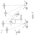
- Fig. 1 illustrates a navigation communication system which comprises a plurality of vehicles, each equipped with a mobile vehicle navigation apparatus according to the present invention.
- the navigation communication system comprises a communication service center 1, a relay station 2, GPS (Global Positioning System) satellites 3, and the plurality of vehicles 4 each equipped with the vehicle-equipped navigation apparatus.
- GPS Global Positioning System
- the communication service center 1 is administrated, for example, by a portable telephone business entity for providing a navigation data communication service which utilizes this navigation system only for registered users.
- Fig. 2 illustrates the configuration of a communication service unit installed in the communication service center 1.
- the communication service unit comprises a transmitter/receiver 10 for governing communications with each of the vehicles 4; a database 11; an accounting processor 12; a return acceptance memory 13; and a controller 14 for controlling each of these functional modules.
- the database 11 are registered with data communication channel information allocated to each registered user and bank account information declared by each registered user in correspondence to each user ID.
- the controller 14 Upon receipt of a variety of messages transmitted from the vehicles 4 through the relay station 2 and the transmitter/receiver 10, the controller 14 controls the accounting processor 12 for prompting accounting processing (later described) in accordance with a received message, as described later. Further, the controller 14 controls the transmitter/receiver 10 to forward the message to the mobile vehicle navigation apparatus equipped in a remote vehicle (vehicle 4) indicated by the received message.
- Fig. 3 illustrates the configuration of the mobile vehicle navigation apparatus equipped in each of the vehicles 4.
- the mobile vehicle navigation apparatus comprises an own vehicle position detector circuit 41, a GPS antenna 42, a display device 43, a map data memory 44, a cellular phone transceiver circuit 45, a cellular phone antenna 46, a manipulating part 47, an ID memory 48, and a flag register 49.
- the own vehicle position detector 41 calculates a current position of the vehicle, equipped with the navigation apparatus, based on a received signal generated from radio waves transmitted from the GPS satellites 3 and received through the GPS antenna 42, and supplies the controller 40 with vehicle position information indicative of the position.
- the controller 40 conducts a control in accordance with an own vehicle position display routine (not shown) to display a map with an own vehicle mark added thereto on a display screen of the display device 43. More specifically, the controller 40 first reads map data including a position indicated by the vehicle position information from map data for each regional segment stored in the map data memory 44. Then, the controller 40 generates display map data which has a mark indicative of the own vehicle position superimposed on a map represented by the map data, and supplies the display device 43 with this display map data.
- the manipulating part 47 accepts not only a variety of manipulations for operating the navigation apparatus but also manipulations as described blow (from the user), and supplies the controller 40 with a signal corresponding to each manipulation.
- the manipulation part 47 is used to accept entry and setting for registering a remote vehicle ID; setting as to whether a remote vehicle position is permitted for display; and setting as to whether the own vehicle position may be transmitted to remote vehicles.
- the controller 40 stores in the flag register 49 an own vehicle position transmission disable flag which is at logical level "1" when a setting manipulation is performed to disable the transmission of the own vehicle position through a manipulation of the user using the manipulating part 47, and at logical level "0" when a setting manipulation is performed to enable the transmission of the own vehicle position to remote vehicles.
- the controller 40 stores in the flag register 49 a remote vehicle position display disable flag which is at logical level "1" when a setting manipulation is performed to disable a remote vehicle position to be displayed on the screen of the display device 43 through a manipulation of the user using the manipulation part 47, and at logical level "0" when a setting manipulation is performed to enable the remote vehicle position to be displayed. Further, the controller 40 first supplies the display device 43 with an image display instruction for displaying an ID entry screen as illustrated in Fig. 4 when entry and registration setting manipulations are performed for a remote vehicle ID through manipulations of the user using the manipulating part 47.
- the user manipulates the manipulating part 47 to enter ID of a friend or a user who belongs to a particular group, i.e., a remote vehicle ID in an ID entry field F1 as shown in Fig. 4, and clicks a mouse on a decision button display B2.
- the controller 40 stores the remote vehicle ID entered in the ID entry field F1 in the ID memory 48 for registration, and controls the display device 43 to display the ID in a registered ID list display field F2 in Fig. 4.
- the ID memory 48 previously stores an own vehicle ID other than remote vehicle IDs registered as described above.
- the user manipulates the manipulating part 47 to perform a setting as to whether or not the remote vehicle ID is made valid for each of remote vehicle IDs registered as described above, i.e., remote vehicle IDs displayed in the registered ID list display field F2.
- the user may specify a remote vehicle ID, which he wants to make valid, from the remote vehicle IDs displayed in the registered ID list display field F2, and clicks on an ACT button display B3.
- the controller 40 stores the remote vehicle ID with a valid flag at logical level "1" added thereto in the ID memory 48. In this event, on a valid flag display field F3, a black circle mark is displayed only for the remote vehicle ID to which the valid flag has been added.
- the cellular phone transceiver circuit 45 supplies the controller 40 with a variety of messages (later described) from the communication service center 1 received through the cellular phone antenna 46. Also, the cellular phone transceiver circuit 45 transmits a variety of messages (later described) supplied from the controller 40 to the communication service center 1 through the cellular phone antenna 46.
- the controller 40 proceeds to execution of a remote vehicle position request routine as illustrated in Fig. 5.
- the controller 40 first supplies the display device 43 with an image display instruction for displaying the ID entry screen illustrated in Fig. 4 for the user to specify a remote vehicle to be displayed (step S31).
- the controller 40 determines whether or not the user clicks on a cancel button display B1 shown in Fig. 5 through a cursor manipulation using the manipulating part 47 (step S32).
- the controller 40 determines whether or not the user clicks on the decision button display B2 shown in Fig. 4 by a cursor manipulation using the manipulating part 47 (step S33).
- the controller 40 returns to the execution of step S32 to repeatedly perform the operation as described above.
- the user manipulates the manipulating part 47 to enter a remote ID indicative of a party (remote vehicle), the current position of which the user wants to confirm, in the ID entry field F1 as shown in Fig. 4.
- the user may specify a remote vehicle ID, the current position of which he wants to confirm, from the registered ID list display field F2 which displays previously registered remote vehicle IDs in the form of list, instead of entering a remote vehicle ID in the ID entry field F1.
- the controller 40 As the user has entered or specified the remote vehicle ID as described above, the user clicks on the decision button display B2 through a cursor manipulation using the manipulating part 47. In response to this clicking, the controller 40 generates a remote vehicle position request message as shown in Fig. 6, and supplies this to the cellular phone transceiver circuit 45 (step S34). Specifically, the controller 40 first sets the own vehicle ID as a requesting vehicle ID, and the remote vehicle ID entered in the remote vehicle ID entry field F1 (or the specified remote vehicle ID) as a requested vehicle ID. Then, the controller 40 adds a remote vehicle position request code OPR to the head of these requesting vehicle ID and requested vehicle ID to generate the remote vehicle position request message as shown in Fig. 6 which is transmitted to the communication service center 1.
- step S34 the controller 40 exits the remote vehicle position request routine illustrated in Fig. 5 to return to the execution of a main routine (not described).
- the controller 40 proceeds to execution of a vehicle position spontaneous transmission routine as illustrated in Fig. 7.
- the controller 40 first supplies the display device 43 with an image display instruction for displaying the ID entry screen illustrated in Fig. 4 for the user to specify a remote vehicle to which the own vehicle position is to be transmitted (step S71).
- the controller 40 determines whether or not the user clicks on a cancel button display B1 shown in Fig. 4 through a cursor manipulation using the manipulating part 47 (step S72).
- the controller 40 determines whether or not the user clicks on the decision button display B2 shown in Fig. 4 (step S73).
- the controller 40 returns to the execution of step S72 to repeatedly perform the operation as described above.
- the user manipulates the manipulating part 47 to enter a remote ID indicative of a party (remote vehicle), to which the own vehicle position is notified, in the remote vehicle ID entry field F1 as shown in Fig. 4.
- the user may specify a remote vehicle ID, to which the own vehicle position is notified, from the registered ID list display field F2 which displays previously registered remote vehicle IDs in the form of list, instead of entering a remote vehicle ID in the ID entry field F1.
- the controller 40 As the user has entered or specified the remote vehicle ID as described above, the user clicks on the decision button display B2 through a cursor manipulation using the manipulating part 47. In response to this clicking, the controller 40 generates a vehicle position spontaneous transmission message as shown in Fig. 8, and supplies this to the cellular phone transceiver circuit 45 (step S74). Specifically, the controller 40 first sets the own vehicle ID as an originating vehicle ID, and the remote vehicle ID entered in the remote vehicle ID entry field F1 (or the specified remote vehicle ID) as a destination vehicle ID, and adds vehicle position information supplied from the own vehicle position detector circuit 41 to this sequence. Then, the controller 40 adds a vehicle position spontaneous transmission code CPT to the head of the sequence to generate a remote vehicle position request message as shown in Fig.
- step S74 or when determining at step S72 that the user clicks on the cancel button display B1, the controller 40 exits the vehicle position spontaneous transmission routine illustrated in Fig. 7 to return to the execution of a main routine (not described).
- the controller 14 executes a message forward subroutine as illustrated in Fig. 9.
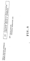
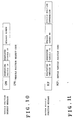
- the controller 14 first determines whether or not a message received by the transmitter/receiver 10 is a remote vehicle position request message as shown in Fig. 6 (step S91). When determining at step S91 that the received message is the remote vehicle position request message, the controller 14 issues a message number MN corresponding to this remote vehicle position request message (step S92). Next, the controller 14 stores the requesting vehicle ID and requested vehicle ID in the remote vehicle position request message, current time information and the message number MN in correspondence in the return acceptance memory 13 (step S93). Next, the controller 14 generates a vehicle position request message as shown in Fig. 10 which includes the requesting vehicle ID, requested vehicle ID, message number MN, and vehicle position request code CPR added to the head of the sequence.
- the controller 14 controls the transmitter/receiver 10 to transmit the vehicle position request message to a vehicle 4 which corresponds to the requested vehicle ID (step S94). Specifically, the controller 14 searches the database 11 for a data communication channel corresponding to the requested vehicle ID, and controls the transmitter/receiver 10 to establish a line connection with the data communication channel to transmit the vehicle position request message. With the execution of step S94, the transmitter/receiver 10 transmits the vehicle position request message to the vehicle 4 indicated by the requested vehicle ID.
- the controller 14 determines whether or not the received message is a vehicle position spontaneous transmission message as shown in Fig. 8 (step S95).
- the controller 14 controls the accounting processor 12 to collect a predetermined service commission from a registered user indicated by an originating vehicle ID in the vehicle position spontaneous transmission message (step S96). Specifically, the controller 14 searches bank account information stored in the database 11 for a bank account number of the registered user corresponding to the originating vehicle ID, and supplies the bank account number to the accounting processor 12. In response, the accounting processor 12 transfers the service commission from the bank account indicated by the bank account number supplied from the controller 14.
- step S96 the controller 14 controls the transmitter/receiver 10 to forward the received vehicle position spontaneous transmission message as it is to a vehicle 4 corresponding to the destination vehicle ID (step S97). Specifically, the controller 14 searches the database 11 for a data communication channel corresponding to the destination vehicle ID, and controls the transmitter/receiver 10 to establish a line connection with the data communication channel to transmit the vehicle position spontaneous transmission message. With the execution of step S97, the transmitter/receiver 10 transmits the vehicle position spontaneous transmission message to the vehicle 4 indicated by the destination vehicle ID.
- step S98 determines whether or not the received message is a return vehicle position message (later described) (step S98).
- the controller 14 extracts the message number MN described in the return vehicle position message, and reads a requesting vehicle ID stored in correspondence to this message number MN from the return acceptance memory 13 (step S99).
- the controller 14 determines whether or not the requesting vehicle ID read from the return acceptance memory 13 matches the requesting vehicle ID indicated in the return vehicle position message (step S100).
- the controller 14 controls the accounting processor 12 to collect a predetermined service commission from a registered user indicated by the requesting vehicle ID (step S101). Specifically, the controller 14 searches bank account information stored in the database 11 for a bank account number of the registered user corresponding to the requesting vehicle ID, and supplies the bank account number to the accounting processor 12. In response, the accounting processor 12 transfers the service commission from the bank account indicated by the bank account number supplied from the controller 14. After the execution of step S101, the controller 14 controls the transmitter/receiver 10 to forward the received return vehicle position message to a vehicle 4 corresponding to the requesting vehicle ID described in the return vehicle position message (step S102).
- the controller 14 searches the database 11 for a data communication channel corresponding to the requesting vehicle ID, and controls the transmitter/receiver 10 to establish a line connection with the data communication channel to transmit the return vehicle position message.
- the transmitter/receiver 10 transmits the return vehicle position message to the vehicle 4 indicated by the requesting vehicle ID.
- step S100 when determining at step S100 that the requesting vehicle ID read from the return acceptance memory 13 does not match the requesting vehicle ID indicated in the return vehicle position message, the controller 14 issues an error number (step S103). Then, the controller 14 stores each of the requesting vehicle ID, requested vehicle ID and message number MN indicated in the return vehicle position message in correspondence to the error number in the return acceptance memory 13 (step S104).
- step S104 After the execution of step S104, S94, S97 or S102, the controller 14 exits the message forward routine illustrated in Fig. 9 to return to the execution of the main routine (not described).
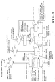
- the controller 40 proceeds to execution of a vehicle position request return routine as illustrated in Fig. 12.
- the controller 40 first determines whether a requested vehicle ID described in the vehicle position request message as shown in Fig. 10, received by the cellular phone transceiver circuit 45 matches the own vehicle ID (step S120). When determining at step S120 that both IDs match, the controller 40 determines whether or not an own vehicle position transmission disable flag stored in the flag register 49 is at logical level "1" indicating that the transmission of the own vehicle position is disabled (step S121). When determining at step S121 that the own vehicle position transmission disable flag is not at logical level "1" indicating that the transmission of the own vehicle position is disabled, the controller 40 determines whether or not the same remote vehicle ID as the requesting vehicle ID indicated by the vehicle position request message is stored in the ID memory 48 (step S122).
- step S122 the controller 40 determines whether or not the requesting vehicle ID indicated in the vehicle position request message has been registered in the ID memory 48.
- the controller 40 determines whether or not a valid flag at logical level "1" is added to this remote vehicle ID (step S123).
- the controller 40 generates a return vehicle position message as shown in Fig. 11, and supplies this message to the cellular phone transceiver circuit 45 (step S124).
- the controller 40 first adds vehicle position information supplied from the own vehicle position detector circuit 41 to the requesting vehicle ID, requested vehicle ID and message number MN in the received vehicle position request message (shown in Fig. 10). Then, the controller 40 generates a return vehicle position message as shown in Fig. 11 by adding a return vehicle position code RCP to the head of the sequence, and transmits this message to the communication service center 1.
- the controller 40 determines whether or not the requesting vehicle ID has been set in a valid state through a manipulation of the user using the manipulating part 47 (step S125).
- the controller 40 executes the foregoing step S124 to transmit a return vehicle position message as shown in Fig. 11 to the communication service center 1.
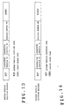
- the controller 40 when determining at step S125 that the requesting vehicle ID is not set in the valid state, the controller 40 generates a return vehicle position message having a format shown in Fig. 13 instead of that shown in Fig.
- step S126 when the requesting vehicle ID is set in an invalid state, the controller 40 omits vehicle position information from the return vehicle position message shown in Fig. 11, and adds a first error code ERR1, indicating that the transmission of the own vehicle position is rejected, to generate a return vehicle position message (shown in Fig. 13), and transmits this message to the communication service center 1. It should be noted that the controller 40 also executes step S126 when determining at step S123 that the valid flag at logical level "1" is not added to the requesting vehicle ID, or when determining at step S121 that the own vehicle position transmission disable flag is at logical level "1" indicating that the transmission of the own vehicle position is disabled.
- the controller 40 when determining at step S120 that the requesting vehicle ID indicated in the received vehicle position request message as described above does not match the own vehicle ID, the controller 40 generates a return vehicle position message having a format shown in Fig. 14 instead of that shown in Fig. 11, and supplies this message to the cellular phone transceiver circuit 45 (step S127). Specifically, the controller 40 omits the vehicle position information from the return vehicle position message shown in Fig. 11, and adds a second error code ERR2, pointing out that the ID is improper, to generate a return vehicle position message as shown in Fig. 14, and transmits this message to the communication service center 1.
- ERR2 second error code
- the controller 40 exits the vehicle position request return routine as illustrated in Fig. 12 to return to the execution of the main routine.
- the controller 40 proceeds to execution of a remote vehicle position display routine as illustrated in Fig. 15.
- the controller 40 first determines whether or not the first error code ERR1 or the second error code ERR2 shown in Fig. 13 or 14 exists in the received message (step S130). When determining at step S130 that the first error code ERR1 or the second error code ERR2 exists in the received message, the controller 40 supplies the display device 43 with an image display instruction to display the contents indicated by each of these error codes (step S131). On the other hand, when determining at step S130 that either of the error codes does not exist in the received message, the controller 40 starts counting using a first built-in timer (not shown) (step S132).
- the controller 40 determines whether or not a remote vehicle position display disable flag stored in the flag register 49 is at logical level "1" indicating that display of the remote vehicle position is disabled (step S133). Determining at step S133 that the remote vehicle position display disable flag is at logical level "1,” the controller 40 notifies that a vehicle position spontaneous transmission message or a return vehicle position message has been received, and supplies the display device 43 with an image display instruction to display an originating vehicle ID (requested vehicle ID) described in the message (step S134). Next, the controller 40 determines whether or not a count value indicated by the first built-in timer is larger than a predetermined value (step S135).
- the controller 40 When determining at step S135 that the count value indicated by the first built-in timer is smaller than the predetermined value, the controller 40 returns to the execution of step S133 to repeatedly execute the operation as described above. Specifically, until the count value indicated by the first built-in timer exceeds the predetermined value, the controller 40 waits for the user to release the disabled remote vehicle position display, i.e., to set the remote vehicle position display disable flag to logical level "0" through a manual manipulation. Incidentally, as the user manipulates the manipulating part 47 to enable the remote vehicle position to be displayed, the remote vehicle position display disable flag stored in the flag register 49 transitions to logical level "0."
- step S133 When determining at step S133 that the remote vehicle position display disable flag is not at logical level "1," i.e., display is not disabled, the controller 40 start counting using a second built-in timer (not shown) (step S136). Next, the controller 40 determines whether or not the same remote vehicle ID as the originating vehicle ID (requested vehicle ID) described in the received message is stored in the ID memory 48 (step S137). In other word, with the execution of step S137, the controller 40 determines whether or not the originating vehicle ID (requested vehicle ID) described in the received vehicle position spontaneous transmission message (or the return vehicle position message) has been registered in the ID memory 48.
- the controller 40 determines whether or not a valid flag at logical level "1" is added to the remote vehicle ID (step S138).
- the controller 40 proceeds to execution of a remote vehicle position display routine (step S139).
- the controller 40 first fetches vehicle position information described in the received vehicle position spontaneous transmission message (Fig. 8) or return vehicle position message (Fig. 11) as remote vehicle position information.
- the controller 40 fetches vehicle position information supplied form the own vehicle position detector circuit 41 as own vehicle position information.
- the controller 40 reads map data including a position indicated by the remote vehicle position information and a position indicated by the own vehicle position information from map data of each regional segment stored in the map data memory 44. Then, the controller 40 generates display map data with a remote vehicle position mark added at the position indicated by the remote vehicle position information and an own vehicle position mark added at the position indicated by the own vehicle position information, and supplies this display map data to the display unit 43. In this way, a map with the added own vehicle position mark and remote vehicle position mark is displayed on the screen of the display device 43.
- step S137 when determining at step S137 that the originating vehicle ID (requesting vehicle ID) described in the vehicle position spontaneous transmission message or the return vehicle position message is not stored in the ID memory 48, the controller 40 determines whether or not the originating vehicle ID (requesting vehicle ID) has been set in a valid state through a manipulation of the user using the manipulating part 47 (step S140).
- step S140 the controller 40 next executes the foregoing step S139 to display the remote vehicle position together with the own vehicle position on the screen of the display unit 43, as described above.
- step S140 when determining at step S140 that the originating vehicle ID (requesting vehicle ID) is not set in the valid state, i.e., it is set in an invalid state, the controller 40 supplies the display device 43 with an image display instruction to display a message which points out that the originating vehicle ID (requesting vehicle ID) is in the invalid state (step S141).
- step S141 is also executed when the controller 40 determines at step S138 that the valid flag at logical level "1" is not added to the same remote vehicle ID as the originating vehicle ID (requesting vehicle ID).
- step S142 determines whether or not a count value indicated by the second built-in timer is larger than a predetermined value
- step S142 When determining at step S142 that the count value indicated by the second built-in timer is smaller than the predetermined value, the controller 40 returns to the execution of step S137 to repeatedly execute the operation as described above. Specifically, until the count value indicated by the second built-in timer exceeds the predetermined value, the controller 40 waits for the user to set the originating vehicle ID (requesting vehicle ID) in the valid state through a manual manipulation.
- the controller 40 exits the remote vehicle position display routine as illustrated in Fig. 15 to proceed to the execution of the main routine.
- the remote vehicle position display routine (step S139) is not executed, so that the position of a vehicle (remote vehicle) indicated by this originating vehicle ID (requesting vehicle ID) is not displayed on the display device 43.
- the navigation communication system has a vehicle position spontaneous transmission mode for voluntarily transmitting the position of the own vehicle to a specified remote vehicle, in addition to a remote vehicle position display mode for displaying the position of a remote vehicle, together with the position of the own vehicle, on the display device 43.
- Fig. 16 illustrates a communication operation performed between the vehicles 4a, 4b and the communication service center 1 in the remote vehicle position display mode.
- Fig. 16 illustrates the operation performed when the vehicle 4a (own vehicle) displays a current position of the vehicle 4b (remote vehicle) on the display device 43 equipped in the own vehicle.
- the user in the vehicle 4a manipulates the manipulating part 47 to enter ID of the vehicle 4b in the remote vehicle ID entry field F1 as shown in Fig. 4 to issue a remote vehicle position display instruction.
- the remote vehicle position request routine as illustrated in Fig. 5 is executed, wherein at step S34, a remote vehicle position request message as shown in Fig. 6 is transmitted from the vehicle 4a to the communication service center 1.
- the message forward routine illustrated in Fig. 9 is executed. Then, at step S94 of the message forward routine, a vehicle position request message as shown in Fig. 10 is transmitted to a requested vehicle ID described in the received remote vehicle position request message, i.e., to the vehicle 4b.
- step S124 is executed in the vehicle 4b.
- the vehicle 4b When a requesting vehicle ID described in the vehicle position request message (i.e., that indicative of the vehicle 4a) is set in the valid state, step S124 is executed in the vehicle 4b.
- the vehicle 4b When the requested vehicle ID described in the vehicle position request message (i.e., that indicative of the vehicle 4b) is different from ID of the vehicle 4b itself, step S127 is executed instead of step S124.
- the vehicle 4b transmits to the communication service center 1 a return vehicle position message having the format as shown in Fig. 14, to which the second error code ERR2 is added for pointing out that the ID is improper, instead of the vehicle position information.
- step S126 is executed instead of the aforementioned step S124.
- the vehicle 4b transmits to the communication service center 1 a return vehicle position message having the format as shown in Fig. 13, to which the first error code ERR1 is added for indicating that the vehicle 4b rejects to notify the vehicle 4a of its own vehicle position (vehicle 4b), instead of the vehicle position information.
- the communication service center 1 Upon receipt of the return vehicle position request message from the vehicle 4b, the communication service center 1 executes the message forward routine illustrated in Fig. 9, wherein a service commission is transferred from a bank account of a requesting vehicle ID (vehicle 4a) described in the message (step S101). Then, the communication service center 1 forwards this return vehicle position message to the requesting vehicle ID described in the return vehicle position message, i.e., to the vehicle 4a, by executing step S102.
- step S139 is executed. Specifically, when the requested vehicle ID indicative of the vehicle 4b is set in the valid state, the position of the vehicle 4b (remote vehicle) is displayed together with the position of the vehicle 4a (own vehicle) on the screen of the display device 43 equipped in the vehicle 4a by the execution of step S139.
- step S139 is not executed. Specifically, only the position of the vehicle 4a (own vehicle) is displayed but not the position of the vehicle 4b (remote vehicle) on the screen of the display device 43 equipped in the vehicle 4a.
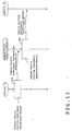
- Fig. 17 illustrates a communication operation performed between the vehicles 4a, 4b and the communication service center 1 in the vehicle position spontaneous transmission mode.
- Fig. 17 illustrates the operation performed when the vehicle 4a (own vehicle) transmits its own current position to the vehicle 4b (remote vehicle).
- the user in the vehicle 4a manipulates the manipulating part 47 to enter ID of the vehicle 4b in the remote vehicle ID entry field F1 as shown in Fig. 4 to issue a vehicle position spontaneous transmission instruction.
- the vehicle position spontaneous transmission routine as illustrated in Fig. 7 is executed, wherein at step S74, a vehicle position spontaneous transmission message as shown in Fig. 8 is transmitted from the vehicle 4a to the communication service center 1.
- the communication service center 1 Upon receipt of the vehicle position spontaneous transmission message from the vehicle 4a, the communication service center 1 executes the message forward routine illustrated in Fig. 9, wherein a service commission is first transferred from a bank account of an originating vehicle ID (vehicle 4a) described in the message (step S96). Then, the communication service center 1 forwards this vehicle position spontaneous transmission message to a vehicle indicated by the destination vehicle ID described in the vehicle position spontaneous transmission message, i.e., to the vehicle 4b, by the execution of step S97.
- step S139 is executed. Specifically, when the originating vehicle ID indicative of the vehicle 4a is set in the valid state, the position of the vehicle 4a is displayed together with the position of the vehicle 4b on the screen of the display device 43 equipped in the vehicle 4b by the execution of step S139.
- step S139 is not executed, in which case only a current position of the vehicle 4b is displayed on the screen of the display device 43 equipped in the vehicle 4b.
- the mobile vehicle navigation apparatus displays only the position of a vehicle (remote vehicle) which is set in a valid state by the user, a clear navigation display can be provided. Also, in the navigation communication system according to the present invention, even if a request for vehicle position information is made from a remote vehicle, the position of the vehicle is not notified except for vehicles which are set in a valid state by the user, thereby making it possible to prevent own vehicle position information from draining out to third parties.
Landscapes
- Engineering & Computer Science (AREA)
- Radar, Positioning & Navigation (AREA)
- Remote Sensing (AREA)
- Automation & Control Theory (AREA)
- Physics & Mathematics (AREA)
- General Physics & Mathematics (AREA)
- Navigation (AREA)
- Traffic Control Systems (AREA)
- Position Fixing By Use Of Radio Waves (AREA)
- Instructional Devices (AREA)
Abstract
A vehicle-equipped navigation apparatus and a navigation communication system which are capable of providing a clear display and preventing own vehicle position information from draining out to third parties. A setting part is provided for setting a remote vehicle either in a valid state or in an invalid state, such that only a remote vehicle position transmitted from a remote vehicle set in the valid state is displayed on a display together with an own vehicle position.
Description
The present invention relates to a navigation
apparatus and a navigation system for displaying a current
position of a mobile vehicle.
Nowadays, a navigation apparatus for mounting in a
vehicle, referred to as in-vehicle navigation system
hereinafter, is commercially available, which utilizes GPS
(Global Positioning System) satellites or the like to
calculate a current position of a vehicle and display a
mark indicative of the current position superimposed on a
displayed map. Furthermore, a study has been made on a
type of in-vehicle navigation apparatus having a
communication function which transmits a current position
mutually with a plurality of vehicles so that the
positions of other vehicles as well as the position of the
vehicle itself can be displayed on the same screen.
However, with such an in-vehicle navigation apparatus
a problem may be encountered that, as the number of
vehicles increases, a larger number of position marks
appear on the display screen to result in an disorderly
display, and also the position of the vehicle would be
known to unintended third parties.
The present invention has been made to solve the
above problem, and an object of the present invention is
to provide a mobile vehicle navigation apparatus and a
navigation communication system which are capable of
offering a clear display and preventing vehicle position
information from draining out to third parties.
A mobile vehicle navigation apparatus according to
the present invention displaying the position of a mobile
vehicle on a display, comprises a receiver for receiving
information transmitted from another mobile vehicle,
indicative of the position of the other mobile vehicle, a
setting unit for setting the other mobile vehicle in
either a valid state or an invalid state, and a display
unit for displaying the position of the other mobile
vehicle received by the receiver on the display when the
other mobile vehicle is set in the valid state.
Also, a navigation communication system according to
the present invention is comprised of a mobile vehicle
navigation apparatus equipped in each of a plurality of
mobile vehicles for displaying the position of the mobile
vehicle on a display, and a communication service center,
wherein the mobile vehicle navigation apparatus equipped
in one mobile vehicle comprises an own position detector
for detecting its own position, and a transmitter for
transmitting position information indicative of the own
position to the communication service center to transmit
the position information to a mobile vehicle navigation
apparatus equipped in another mobile vehicle, the
communication service center comprises a receiver for
receiving the position information transmitted from the
mobile vehicle navigation apparatus equipped in the one
mobile vehicle, and a transmitter for transmitting the
received position information to a mobile vehicle
navigation apparatus equipped in another mobile vehicle,
and the mobile vehicle navigation apparatus equipped in
the other mobile vehicle comprises a receiver for
receiving the position information transmitted from the
communication service center, and a display unit for
displaying the position of the mobile vehicle on a display
based on the received position information, wherein the
position of the one mobile vehicle is displayed on the
display of the mobile vehicle navigation apparatus
equipped in the other mobile vehicle.
In the following, one embodiment of the present
invention will be described in detail with reference to
the accompanying drawings.
Fig. 1 illustrates a navigation communication system
which comprises a plurality of vehicles, each equipped
with a mobile vehicle navigation apparatus according to
the present invention.
As illustrated in Fig. 1, the navigation
communication system comprises a communication service
center 1, a relay station 2, GPS (Global Positioning
System) satellites 3, and the plurality of vehicles 4 each
equipped with the vehicle-equipped navigation apparatus.
The communication service center 1 is administrated,
for example, by a portable telephone business entity for
providing a navigation data communication service which
utilizes this navigation system only for registered users.
Fig. 2 illustrates the configuration of a
communication service unit installed in the communication
service center 1.
As illustrated in Fig. 2, the communication service
unit comprises a transmitter/receiver 10 for governing
communications with each of the vehicles 4; a database 11;
an accounting processor 12; a return acceptance memory 13;
and a controller 14 for controlling each of these
functional modules. The database 11 are registered with
data communication channel information allocated to each
registered user and bank account information declared by
each registered user in correspondence to each user ID.
Upon receipt of a variety of messages transmitted
from the vehicles 4 through the relay station 2 and the
transmitter/receiver 10, the controller 14 controls the
accounting processor 12 for prompting accounting
processing (later described) in accordance with a received
message, as described later. Further, the controller 14
controls the transmitter/receiver 10 to forward the
message to the mobile vehicle navigation apparatus
equipped in a remote vehicle (vehicle 4) indicated by the
received message.
Fig. 3 illustrates the configuration of the mobile
vehicle navigation apparatus equipped in each of the
vehicles 4.
As illustrated in Fig. 3, the mobile vehicle
navigation apparatus comprises an own vehicle position
detector circuit 41, a GPS antenna 42, a display device 43,
a map data memory 44, a cellular phone transceiver circuit
45, a cellular phone antenna 46, a manipulating part 47,
an ID memory 48, and a flag register 49.
The own vehicle position detector 41 calculates a
current position of the vehicle, equipped with the
navigation apparatus, based on a received signal generated
from radio waves transmitted from the GPS satellites 3 and
received through the GPS antenna 42, and supplies the
controller 40 with vehicle position information indicative
of the position. The controller 40 conducts a control in
accordance with an own vehicle position display routine
(not shown) to display a map with an own vehicle mark
added thereto on a display screen of the display device 43.
More specifically, the controller 40 first reads map data
including a position indicated by the vehicle position
information from map data for each regional segment stored
in the map data memory 44. Then, the controller 40
generates display map data which has a mark indicative of
the own vehicle position superimposed on a map represented
by the map data, and supplies the display device 43 with
this display map data.
The manipulating part 47 accepts not only a variety
of manipulations for operating the navigation apparatus
but also manipulations as described blow (from the user),
and supplies the controller 40 with a signal corresponding
to each manipulation. Specifically, the manipulation part
47 is used to accept entry and setting for registering a
remote vehicle ID; setting as to whether a remote vehicle
position is permitted for display; and setting as to
whether the own vehicle position may be transmitted to
remote vehicles. Here, the controller 40 stores in the
flag register 49 an own vehicle position transmission
disable flag which is at logical level "1" when a setting
manipulation is performed to disable the transmission of
the own vehicle position through a manipulation of the
user using the manipulating part 47, and at logical level
"0" when a setting manipulation is performed to enable the
transmission of the own vehicle position to remote
vehicles. Also, the controller 40 stores in the flag
register 49 a remote vehicle position display disable flag
which is at logical level "1" when a setting manipulation
is performed to disable a remote vehicle position to be
displayed on the screen of the display device 43 through a
manipulation of the user using the manipulation part 47,
and at logical level "0" when a setting manipulation is
performed to enable the remote vehicle position to be
displayed. Further, the controller 40 first supplies the
display device 43 with an image display instruction for
displaying an ID entry screen as illustrated in Fig. 4
when entry and registration setting manipulations are
performed for a remote vehicle ID through manipulations of
the user using the manipulating part 47. Here, the user
manipulates the manipulating part 47 to enter ID of a
friend or a user who belongs to a particular group, i.e.,
a remote vehicle ID in an ID entry field F1 as shown in
Fig. 4, and clicks a mouse on a decision button display B2.
In response to these manipulations, the controller 40
stores the remote vehicle ID entered in the ID entry field
F1 in the ID memory 48 for registration, and controls the
display device 43 to display the ID in a registered ID
list display field F2 in Fig. 4. The ID memory 48
previously stores an own vehicle ID other than remote
vehicle IDs registered as described above. Further, the
user manipulates the manipulating part 47 to perform a
setting as to whether or not the remote vehicle ID is made
valid for each of remote vehicle IDs registered as
described above, i.e., remote vehicle IDs displayed in the
registered ID list display field F2. For example, the user
may specify a remote vehicle ID, which he wants to make
valid, from the remote vehicle IDs displayed in the
registered ID list display field F2, and clicks on an ACT
button display B3. In response to the clicking, the
controller 40 stores the remote vehicle ID with a valid
flag at logical level "1" added thereto in the ID memory
48. In this event, on a valid flag display field F3, a
black circle mark is displayed only for the remote vehicle
ID to which the valid flag has been added.
The cellular phone transceiver circuit 45 supplies
the controller 40 with a variety of messages (later
described) from the communication service center 1
received through the cellular phone antenna 46. Also, the
cellular phone transceiver circuit 45 transmits a variety
of messages (later described) supplied from the controller
40 to the communication service center 1 through the
cellular phone antenna 46.
In the following, the operation of the mobile vehicle
navigation apparatus will be described.
First, as the user manipulates the manipulating part
47 to issue a remote vehicle position display instruction,
the controller 40 proceeds to execution of a remote
vehicle position request routine as illustrated in Fig. 5.
In Fig. 5, the controller 40 first supplies the
display device 43 with an image display instruction for
displaying the ID entry screen illustrated in Fig. 4 for
the user to specify a remote vehicle to be displayed (step
S31). Next, the controller 40 determines whether or not
the user clicks on a cancel button display B1 shown in Fig.
5 through a cursor manipulation using the manipulating
part 47 (step S32). When determining at step S32 that the
user does not click on the cancel button display B1, the
controller 40 determines whether or not the user clicks on
the decision button display B2 shown in Fig. 4 by a cursor
manipulation using the manipulating part 47 (step S33).
When determining at step S33 that the user does not click
on the decision button display B2, the controller 40
returns to the execution of step S32 to repeatedly perform
the operation as described above.
Incidentally, the user manipulates the manipulating
part 47 to enter a remote ID indicative of a party (remote
vehicle), the current position of which the user wants to
confirm, in the ID entry field F1 as shown in Fig. 4.
Alternatively, the user may specify a remote vehicle ID,
the current position of which he wants to confirm, from
the registered ID list display field F2 which displays
previously registered remote vehicle IDs in the form of
list, instead of entering a remote vehicle ID in the ID
entry field F1.
As the user has entered or specified the remote
vehicle ID as described above, the user clicks on the
decision button display B2 through a cursor manipulation
using the manipulating part 47. In response to this
clicking, the controller 40 generates a remote vehicle
position request message as shown in Fig. 6, and supplies
this to the cellular phone transceiver circuit 45 (step
S34). Specifically, the controller 40 first sets the own
vehicle ID as a requesting vehicle ID, and the remote
vehicle ID entered in the remote vehicle ID entry field F1
(or the specified remote vehicle ID) as a requested
vehicle ID. Then, the controller 40 adds a remote vehicle
position request code OPR to the head of these requesting
vehicle ID and requested vehicle ID to generate the remote
vehicle position request message as shown in Fig. 6 which
is transmitted to the communication service center 1.
After the execution of step S34, or when determining
at step S32 that the user clicks on the cancel button
display B1, the controller 40 exits the remote vehicle
position request routine illustrated in Fig. 5 to return
to the execution of a main routine (not described).
Alternatively, as the user performs an own vehicle
position spontaneous transmission instruction through a
manipulation on the manipulating part 47, the controller
40 proceeds to execution of a vehicle position spontaneous
transmission routine as illustrated in Fig. 7.
In Fig. 7, the controller 40 first supplies the
display device 43 with an image display instruction for
displaying the ID entry screen illustrated in Fig. 4 for
the user to specify a remote vehicle to which the own
vehicle position is to be transmitted (step S71). Next,
the controller 40 determines whether or not the user
clicks on a cancel button display B1 shown in Fig. 4
through a cursor manipulation using the manipulating part
47 (step S72). When determining at step S72 that the user
does not click on the cancel button display B1, the
controller 40 determines whether or not the user clicks on
the decision button display B2 shown in Fig. 4 (step S73).
When determining at step S73 that the user does not click
on the decision button display B2, the controller 40
returns to the execution of step S72 to repeatedly perform
the operation as described above.
Incidentally, the user manipulates the manipulating
part 47 to enter a remote ID indicative of a party (remote
vehicle), to which the own vehicle position is notified,
in the remote vehicle ID entry field F1 as shown in Fig. 4.
Alternatively, in this event, the user may specify a
remote vehicle ID, to which the own vehicle position is
notified, from the registered ID list display field F2
which displays previously registered remote vehicle IDs in
the form of list, instead of entering a remote vehicle ID
in the ID entry field F1.
As the user has entered or specified the remote
vehicle ID as described above, the user clicks on the
decision button display B2 through a cursor manipulation
using the manipulating part 47. In response to this
clicking, the controller 40 generates a vehicle position
spontaneous transmission message as shown in Fig. 8, and
supplies this to the cellular phone transceiver circuit 45
(step S74). Specifically, the controller 40 first sets the
own vehicle ID as an originating vehicle ID, and the
remote vehicle ID entered in the remote vehicle ID entry
field F1 (or the specified remote vehicle ID) as a
destination vehicle ID, and adds vehicle position
information supplied from the own vehicle position
detector circuit 41 to this sequence. Then, the controller
40 adds a vehicle position spontaneous transmission code
CPT to the head of the sequence to generate a remote
vehicle position request message as shown in Fig. 8 which
is transmitted to the communication service center 1.
After the execution of step S74, or when determining at
step S72 that the user clicks on the cancel button display
B1, the controller 40 exits the vehicle position
spontaneous transmission routine illustrated in Fig. 7 to
return to the execution of a main routine (not described).
Next, the operation performed in the communication
service unit (illustrated in Fig. 2) in the communication
service center 1 will be described when the communication
service center 1 receives a variety of messages
transmitted by the vehicle 4 as described above.
As the transmitter/receiver 10 of the communication
service unit receives a variety of messages from the
vehicle 4, the controller 14 executes a message forward
subroutine as illustrated in Fig. 9.
In Fig. 9, the controller 14 first determines whether
or not a message received by the transmitter/receiver 10
is a remote vehicle position request message as shown in
Fig. 6 (step S91). When determining at step S91 that the
received message is the remote vehicle position request
message, the controller 14 issues a message number MN
corresponding to this remote vehicle position request
message (step S92). Next, the controller 14 stores the
requesting vehicle ID and requested vehicle ID in the
remote vehicle position request message, current time
information and the message number MN in correspondence in
the return acceptance memory 13 (step S93). Next, the
controller 14 generates a vehicle position request message
as shown in Fig. 10 which includes the requesting vehicle
ID, requested vehicle ID, message number MN, and vehicle
position request code CPR added to the head of the
sequence. Then, the controller 14 controls the
transmitter/receiver 10 to transmit the vehicle position
request message to a vehicle 4 which corresponds to the
requested vehicle ID (step S94). Specifically, the
controller 14 searches the database 11 for a data
communication channel corresponding to the requested
vehicle ID, and controls the transmitter/receiver 10 to
establish a line connection with the data communication
channel to transmit the vehicle position request message.
With the execution of step S94, the transmitter/receiver
10 transmits the vehicle position request message to the
vehicle 4 indicated by the requested vehicle ID.
On the other hand, when determining at step S91 that
the received message is not the remote vehicle position
request message, the controller 14 determines whether or
not the received message is a vehicle position spontaneous
transmission message as shown in Fig. 8 (step S95). When
determining at step S95 that the received message is the
vehicle position spontaneous transmission message, the
controller 14 controls the accounting processor 12 to
collect a predetermined service commission from a
registered user indicated by an originating vehicle ID in
the vehicle position spontaneous transmission message
(step S96). Specifically, the controller 14 searches bank
account information stored in the database 11 for a bank
account number of the registered user corresponding to the
originating vehicle ID, and supplies the bank account
number to the accounting processor 12. In response, the
accounting processor 12 transfers the service commission
from the bank account indicated by the bank account number
supplied from the controller 14. After the execution of
step S96, the controller 14 controls the
transmitter/receiver 10 to forward the received vehicle
position spontaneous transmission message as it is to a
vehicle 4 corresponding to the destination vehicle ID
(step S97). Specifically, the controller 14 searches the
database 11 for a data communication channel corresponding
to the destination vehicle ID, and controls the
transmitter/receiver 10 to establish a line connection
with the data communication channel to transmit the
vehicle position spontaneous transmission message. With
the execution of step S97, the transmitter/receiver 10
transmits the vehicle position spontaneous transmission
message to the vehicle 4 indicated by the destination
vehicle ID.
On the other hand, when determining at step S95 that
the received message is not the vehicle position
spontaneous transmission message, the controller 14
determines whether or not the received message is a return
vehicle position message (later described) (step S98).
When determining at step S98 that the received message is
the return vehicle position message, the controller 14
extracts the message number MN described in the return
vehicle position message, and reads a requesting vehicle
ID stored in correspondence to this message number MN from
the return acceptance memory 13 (step S99). Next, the
controller 14 determines whether or not the requesting
vehicle ID read from the return acceptance memory 13
matches the requesting vehicle ID indicated in the return
vehicle position message (step S100). When determining at
step S100 that both requesting vehicle IDs match, the
controller 14 controls the accounting processor 12 to
collect a predetermined service commission from a
registered user indicated by the requesting vehicle ID
(step S101). Specifically, the controller 14 searches bank
account information stored in the database 11 for a bank
account number of the registered user corresponding to the
requesting vehicle ID, and supplies the bank account
number to the accounting processor 12. In response, the
accounting processor 12 transfers the service commission
from the bank account indicated by the bank account number
supplied from the controller 14. After the execution of
step S101, the controller 14 controls the
transmitter/receiver 10 to forward the received return
vehicle position message to a vehicle 4 corresponding to
the requesting vehicle ID described in the return vehicle
position message (step S102). Specifically, the controller
14 searches the database 11 for a data communication
channel corresponding to the requesting vehicle ID, and
controls the transmitter/receiver 10 to establish a line
connection with the data communication channel to transmit
the return vehicle position message. With the execution of
step S102, the transmitter/receiver 10 transmits the
return vehicle position message to the vehicle 4 indicated
by the requesting vehicle ID.
Conversely, when determining at step S100 that the
requesting vehicle ID read from the return acceptance
memory 13 does not match the requesting vehicle ID
indicated in the return vehicle position message, the
controller 14 issues an error number (step S103). Then,
the controller 14 stores each of the requesting vehicle ID,
requested vehicle ID and message number MN indicated in
the return vehicle position message in correspondence to
the error number in the return acceptance memory 13 (step
S104).
After the execution of step S104, S94, S97 or S102,
the controller 14 exits the message forward routine
illustrated in Fig. 9 to return to the execution of the
main routine (not described).
Here, as the cellular phone transceiver circuit 45
built in the mobile vehicle navigation apparatus of the
vehicle 4 receives the vehicle position request message
transmitted from the communication service center 1 as
described above, the controller 40 proceeds to execution
of a vehicle position request return routine as
illustrated in Fig. 12.
In Fig. 12, the controller 40 first determines
whether a requested vehicle ID described in the vehicle
position request message as shown in Fig. 10, received by
the cellular phone transceiver circuit 45 matches the own
vehicle ID (step S120). When determining at step S120 that
both IDs match, the controller 40 determines whether or
not an own vehicle position transmission disable flag
stored in the flag register 49 is at logical level "1"
indicating that the transmission of the own vehicle
position is disabled (step S121). When determining at step
S121 that the own vehicle position transmission disable
flag is not at logical level "1" indicating that the
transmission of the own vehicle position is disabled, the
controller 40 determines whether or not the same remote
vehicle ID as the requesting vehicle ID indicated by the
vehicle position request message is stored in the ID
memory 48 (step S122). In other words, with the execution
of step S122, the controller 40 determines whether or not
the requesting vehicle ID indicated in the vehicle
position request message has been registered in the ID
memory 48. Here, when determining at step S122 that the
same remote vehicle ID as the requesting vehicle ID has
been stored in the ID memory 48, the controller 40
determines whether or not a valid flag at logical level
"1" is added to this remote vehicle ID (step S123). When
determining at step S123 that the valid flag at logical
level "1" is added, the controller 40 generates a return
vehicle position message as shown in Fig. 11, and supplies
this message to the cellular phone transceiver circuit 45
(step S124). Specifically, the controller 40 first adds
vehicle position information supplied from the own vehicle
position detector circuit 41 to the requesting vehicle ID,
requested vehicle ID and message number MN in the received
vehicle position request message (shown in Fig. 10). Then,
the controller 40 generates a return vehicle position
message as shown in Fig. 11 by adding a return vehicle
position code RCP to the head of the sequence, and
transmits this message to the communication service center
1.
On the other hand, when determining at step S122 that
the requesting vehicle ID indicated in the vehicle
position request message is not stored in the ID memory 48,
the controller 40 determines whether or not the requesting
vehicle ID has been set in a valid state through a
manipulation of the user using the manipulating part 47
(step S125). When determining at step S125 that the
requesting vehicle ID has been set in the valid state, the
controller 40 executes the foregoing step S124 to transmit
a return vehicle position message as shown in Fig. 11 to
the communication service center 1. On the other hand,
when determining at step S125 that the requesting vehicle
ID is not set in the valid state, the controller 40
generates a return vehicle position message having a
format shown in Fig. 13 instead of that shown in Fig. 11,
and supplies this message to the cellular phone
transceiver circuit 45 (step S126). In other words, when
the requesting vehicle ID is set in an invalid state, the
controller 40 omits vehicle position information from the
return vehicle position message shown in Fig. 11, and adds
a first error code ERR1, indicating that the transmission
of the own vehicle position is rejected, to generate a
return vehicle position message (shown in Fig. 13), and
transmits this message to the communication service center
1. It should be noted that the controller 40 also executes
step S126 when determining at step S123 that the valid
flag at logical level "1" is not added to the requesting
vehicle ID, or when determining at step S121 that the own
vehicle position transmission disable flag is at logical
level "1" indicating that the transmission of the own
vehicle position is disabled.
As described above, when the requesting vehicle ID is
set in the invalid state, the transmission of the own
vehicle position is rejected, even if a request is made
therefor.
On the other hand, when determining at step S120 that
the requesting vehicle ID indicated in the received
vehicle position request message as described above does
not match the own vehicle ID, the controller 40 generates
a return vehicle position message having a format shown in
Fig. 14 instead of that shown in Fig. 11, and supplies
this message to the cellular phone transceiver circuit 45
(step S127). Specifically, the controller 40 omits the
vehicle position information from the return vehicle
position message shown in Fig. 11, and adds a second error
code ERR2, pointing out that the ID is improper, to
generate a return vehicle position message as shown in Fig.
14, and transmits this message to the communication
service center 1.
After completion of the foregoing steps S124, S126 or
S127, the controller 40 exits the vehicle position request
return routine as illustrated in Fig. 12 to return to the
execution of the main routine.
When the cellular phone transceiver 45 of the vehicle
4 receives the return vehicle position message (Fig. 11,
13 or 14) or the vehicle position spontaneous transmission
message (Fig. 8) transmitted by the communication service
center 1 as described above, the controller 40 proceeds to
execution of a remote vehicle position display routine as
illustrated in Fig. 15.
In Fig. 15, the controller 40 first determines
whether or not the first error code ERR1 or the second
error code ERR2 shown in Fig. 13 or 14 exists in the
received message (step S130). When determining at step
S130 that the first error code ERR1 or the second error
code ERR2 exists in the received message, the controller
40 supplies the display device 43 with an image display
instruction to display the contents indicated by each of
these error codes (step S131). On the other hand, when
determining at step S130 that either of the error codes
does not exist in the received message, the controller 40
starts counting using a first built-in timer (not shown)
(step S132). Next, the controller 40 determines whether or
not a remote vehicle position display disable flag stored
in the flag register 49 is at logical level "1" indicating
that display of the remote vehicle position is disabled
(step S133). Determining at step S133 that the remote
vehicle position display disable flag is at logical level
"1," the controller 40 notifies that a vehicle position
spontaneous transmission message or a return vehicle
position message has been received, and supplies the
display device 43 with an image display instruction to
display an originating vehicle ID (requested vehicle ID)
described in the message (step S134). Next, the controller
40 determines whether or not a count value indicated by
the first built-in timer is larger than a predetermined
value (step S135). When determining at step S135 that the
count value indicated by the first built-in timer is
smaller than the predetermined value, the controller 40
returns to the execution of step S133 to repeatedly
execute the operation as described above. Specifically,
until the count value indicated by the first built-in
timer exceeds the predetermined value, the controller 40
waits for the user to release the disabled remote vehicle
position display, i.e., to set the remote vehicle position
display disable flag to logical level "0" through a manual
manipulation. Incidentally, as the user manipulates the
manipulating part 47 to enable the remote vehicle position
to be displayed, the remote vehicle position display
disable flag stored in the flag register 49 transitions to
logical level "0."
When determining at step S133 that the remote vehicle
position display disable flag is not at logical level "1,"
i.e., display is not disabled, the controller 40 start
counting using a second built-in timer (not shown) (step
S136). Next, the controller 40 determines whether or not
the same remote vehicle ID as the originating vehicle ID
(requested vehicle ID) described in the received message
is stored in the ID memory 48 (step S137). In other word,
with the execution of step S137, the controller 40
determines whether or not the originating vehicle ID
(requested vehicle ID) described in the received vehicle
position spontaneous transmission message (or the return
vehicle position message) has been registered in the ID
memory 48. Here, when determining at step S137 that the
same remote vehicle ID as the originating vehicle ID
(requested vehicle ID) has been stored in the ID memory 48,
the controller 40 determines whether or not a valid flag
at logical level "1" is added to the remote vehicle ID
(step S138). When determining at step S138 that the valid
flag at logical level "1" is added, the controller 40
proceeds to execution of a remote vehicle position display
routine (step S139). In the remote vehicle position
display routine, the controller 40 first fetches vehicle
position information described in the received vehicle
position spontaneous transmission message (Fig. 8) or
return vehicle position message (Fig. 11) as remote
vehicle position information. Next, the controller 40
fetches vehicle position information supplied form the own
vehicle position detector circuit 41 as own vehicle
position information. Next, the controller 40 reads map
data including a position indicated by the remote vehicle
position information and a position indicated by the own
vehicle position information from map data of each
regional segment stored in the map data memory 44. Then,
the controller 40 generates display map data with a remote
vehicle position mark added at the position indicated by
the remote vehicle position information and an own vehicle
position mark added at the position indicated by the own
vehicle position information, and supplies this display
map data to the display unit 43. In this way, a map with
the added own vehicle position mark and remote vehicle
position mark is displayed on the screen of the display
device 43.
On the other hand, when determining at step S137 that
the originating vehicle ID (requesting vehicle ID)
described in the vehicle position spontaneous transmission
message or the return vehicle position message is not
stored in the ID memory 48, the controller 40 determines
whether or not the originating vehicle ID (requesting
vehicle ID) has been set in a valid state through a
manipulation of the user using the manipulating part 47
(step S140). When determining at step S140 that the
originating vehicle ID has been set in the valid state,
the controller 40 next executes the foregoing step S139 to
display the remote vehicle position together with the own
vehicle position on the screen of the display unit 43, as
described above. On the other hand, when determining at
step S140 that the originating vehicle ID (requesting
vehicle ID) is not set in the valid state, i.e., it is set
in an invalid state, the controller 40 supplies the
display device 43 with an image display instruction to
display a message which points out that the originating
vehicle ID (requesting vehicle ID) is in the invalid state
(step S141). This step S141 is also executed when the
controller 40 determines at step S138 that the valid flag
at logical level "1" is not added to the same remote
vehicle ID as the originating vehicle ID (requesting
vehicle ID). After the execution of step S141, the
controller 40 determines whether or not a count value
indicated by the second built-in timer is larger than a
predetermined value (step S142). When determining at step
S142 that the count value indicated by the second built-in
timer is smaller than the predetermined value, the
controller 40 returns to the execution of step S137 to
repeatedly execute the operation as described above.
Specifically, until the count value indicated by the
second built-in timer exceeds the predetermined value, the
controller 40 waits for the user to set the originating
vehicle ID (requesting vehicle ID) in the valid state
through a manual manipulation.
When the count value indicated by the first (second)
built-in timer exceeds the predetermined value at step
S135 (or S142), or after the execution of the foregoing
step S131 or S139, the controller 40 exits the remote
vehicle position display routine as illustrated in Fig. 15
to proceed to the execution of the main routine.
Specifically, when the originating vehicle ID
(requesting vehicle ID) is set in the invalid state, the
remote vehicle position display routine (step S139) is not
executed, so that the position of a vehicle (remote
vehicle) indicated by this originating vehicle ID
(requesting vehicle ID) is not displayed on the display
device 43.
The following description will be made on the
operation of the navigation communication system with
reference to a communication operation performed between
two vehicles 4a and 4b and the communication service
center 1, as illustrated in Fig. 1. The navigation
communication system has a vehicle position spontaneous
transmission mode for voluntarily transmitting the
position of the own vehicle to a specified remote vehicle,
in addition to a remote vehicle position display mode for
displaying the position of a remote vehicle, together with
the position of the own vehicle, on the display device 43.
Fig. 16 illustrates a communication operation
performed between the vehicles 4a, 4b and the
communication service center 1 in the remote vehicle
position display mode. Fig. 16 illustrates the operation
performed when the vehicle 4a (own vehicle) displays a
current position of the vehicle 4b (remote vehicle) on the
display device 43 equipped in the own vehicle.
First, the user in the vehicle 4a manipulates the
manipulating part 47 to enter ID of the vehicle 4b in the
remote vehicle ID entry field F1 as shown in Fig. 4 to
issue a remote vehicle position display instruction. In
response, the remote vehicle position request routine as
illustrated in Fig. 5 is executed, wherein at step S34, a
remote vehicle position request message as shown in Fig. 6
is transmitted from the vehicle 4a to the communication
service center 1.
In the communication service center 1, as the remote
vehicle position request message is received from the
vehicle 4a, the message forward routine illustrated in Fig.
9 is executed. Then, at step S94 of the message forward
routine, a vehicle position request message as shown in
Fig. 10 is transmitted to a requested vehicle ID described
in the received remote vehicle position request message,
i.e., to the vehicle 4b.
Upon receipt of the vehicle position request message
from the communication service center 1, the vehicle 4b
executes the vehicle position request return routine as
illustrated in Fig. 12. In the vehicle position request
return routine, when a requesting vehicle ID described in
the vehicle position request message (i.e., that
indicative of the vehicle 4a) is set in the valid state,
step S124 is executed in the vehicle 4b. In this way, the
vehicle 4b generates a return vehicle position message
including vehicle position information created by the own
vehicle position detector circuit 41, as shown in Fig. 11,
and transmits this message to the communication service
center 1. When the requested vehicle ID described in the
vehicle position request message (i.e., that indicative of
the vehicle 4b) is different from ID of the vehicle 4b
itself, step S127 is executed instead of step S124. In
this way, the vehicle 4b transmits to the communication
service center 1 a return vehicle position message having
the format as shown in Fig. 14, to which the second error
code ERR2 is added for pointing out that the ID is
improper, instead of the vehicle position information. On
the other hand, when the requesting vehicle ID (i.e., the
vehicle 4a) described in the vehicle position request
message is not set in the valid state, step S126 is
executed instead of the aforementioned step S124.
Specifically, the vehicle 4b transmits to the
communication service center 1 a return vehicle position
message having the format as shown in Fig. 13, to which
the first error code ERR1 is added for indicating that the
vehicle 4b rejects to notify the vehicle 4a of its own
vehicle position (vehicle 4b), instead of the vehicle
position information.
Upon receipt of the return vehicle position request
message from the vehicle 4b, the communication service
center 1 executes the message forward routine illustrated
in Fig. 9, wherein a service commission is transferred
from a bank account of a requesting vehicle ID (vehicle
4a) described in the message (step S101). Then, the
communication service center 1 forwards this return
vehicle position message to the requesting vehicle ID
described in the return vehicle position message, i.e., to
the vehicle 4a, by executing step S102.
Upon receipt of the return vehicle position message
from the communication service center 1, the vehicle 4a
executes the remote vehicle position display routine as
illustrated in Fig. 13. In this event, when determining at
step S138 or S140 that the requested vehicle ID described
in the return vehicle position message (i.e., that
indicative of the vehicle 4b) is set in the valid state,
step S139 is executed. Specifically, when the requested
vehicle ID indicative of the vehicle 4b is set in the
valid state, the position of the vehicle 4b (remote
vehicle) is displayed together with the position of the
vehicle 4a (own vehicle) on the screen of the display
device 43 equipped in the vehicle 4a by the execution of
step S139.
On the other hand, when an error code (ERR1, ERR2) is
described in the received return vehicle position message,
or when the requested vehicle ID indicative of the vehicle
4b is not set in the valid state, the foregoing step S139
is not executed. Specifically, only the position of the
vehicle 4a (own vehicle) is displayed but not the position
of the vehicle 4b (remote vehicle) on the screen of the
display device 43 equipped in the vehicle 4a.
Fig. 17 illustrates a communication operation
performed between the vehicles 4a, 4b and the
communication service center 1 in the vehicle position
spontaneous transmission mode. Fig. 17 illustrates the
operation performed when the vehicle 4a (own vehicle)
transmits its own current position to the vehicle 4b
(remote vehicle).
First, the user in the vehicle 4a manipulates the
manipulating part 47 to enter ID of the vehicle 4b in the
remote vehicle ID entry field F1 as shown in Fig. 4 to
issue a vehicle position spontaneous transmission
instruction. In response, the vehicle position spontaneous
transmission routine as illustrated in Fig. 7 is executed,
wherein at step S74, a vehicle position spontaneous
transmission message as shown in Fig. 8 is transmitted
from the vehicle 4a to the communication service center 1.
Upon receipt of the vehicle position spontaneous
transmission message from the vehicle 4a, the
communication service center 1 executes the message
forward routine illustrated in Fig. 9, wherein a service
commission is first transferred from a bank account of an
originating vehicle ID (vehicle 4a) described in the
message (step S96). Then, the communication service center
1 forwards this vehicle position spontaneous transmission
message to a vehicle indicated by the destination vehicle
ID described in the vehicle position spontaneous
transmission message, i.e., to the vehicle 4b, by the
execution of step S97.
Upon receipt of the vehicle position spontaneous
transmission message from the communication service center
1, the vehicle 4b executes the remote vehicle position
display routine as illustrated in Fig. 13. In this event,
when determining at step S138 or S140 that the originating
vehicle ID described in the vehicle position spontaneous
transmission message (i.e., that indicative of the vehicle
4a) is set in the valid state, step S139 is executed.
Specifically, when the originating vehicle ID indicative
of the vehicle 4a is set in the valid state, the position
of the vehicle 4a is displayed together with the position
of the vehicle 4b on the screen of the display device 43
equipped in the vehicle 4b by the execution of step S139.
On the other hand, when the originating vehicle ID is
not set in the valid state, the foregoing step S139 is not
executed, in which case only a current position of the
vehicle 4b is displayed on the screen of the display
device 43 equipped in the vehicle 4b.
As described above, since the mobile vehicle
navigation apparatus according to the present invention
displays only the position of a vehicle (remote vehicle)
which is set in a valid state by the user, a clear
navigation display can be provided. Also, in the
navigation communication system according to the present
invention, even if a request for vehicle position
information is made from a remote vehicle, the position of
the vehicle is not notified except for vehicles which are
set in a valid state by the user, thereby making it
possible to prevent own vehicle position information from
draining out to third parties.
Claims (7)
- A mobile vehicle navigation apparatus for displaying the position of a mobile vehicle on a display, comprising:a receiver for receiving information transmitted from another mobile vehicle, indicative of the position of said other mobile vehicle;a setting part for setting said other mobile vehicle either in a valid state or in an invalid state; anda display part for displaying the position of said other mobile vehicle received by said receiver on said display when said other mobile vehicle is set in the valid state.
- A mobile vehicle navigation apparatus comprising:a self detector for detecting its own position;a receiver for receiving a mobile vehicle position request message transmitted from another mobile vehicle;setting part for setting said other mobile vehicle either in a valid state or in an invalid state;a determining part responsive to receipt of said mobile vehicle position request message for determining whether or not said other mobile vehicle, which is the originator of said mobile vehicle position request message, is set in the valid state; anda mobile vehicle position return part for returning a mobile vehicle return position message including mobile vehicle position information indicative of the own position to said other mobile vehicle, which is the originator of said mobile vehicle position request message, when said determining part determines that said other mobile vehicle is set in the valid state.
- A mobile vehicle navigation apparatus for displaying the position of a mobile vehicle on a display, comprising:a transmitter for transmitting a mobile vehicle position request message for requesting another mobile vehicle for its position;a receiver for receiving a mobile vehicle position return message returned from said other mobile vehicle, said message including mobile vehicle position information indicative of the position of said other mobile vehicle;a setting part for setting said other mobile vehicle either in a valid state or in an invalid state;a determining part responsive to receipt of said mobile vehicle position return message for determining whether or not said other mobile vehicle, which is the originator of said mobile vehicle position return message, is set in the valid state; anda display part for displaying the position of said other mobile vehicle indicated by mobile vehicle position information included in said mobile vehicle position return message on said display, when said determining part determines that said other mobile vehicle is in the valid state.
- A navigation communication system comprised of a mobile vehicle navigation apparatus equipped in each of a plurality of mobile vehicles for displaying the position of said mobile vehicle on a display, and a communication service center, wherein:wherein the position of said one mobile vehicle is displayed on the display of the mobile vehicle navigation apparatus equipped in said other mobile vehicle.said mobile vehicle navigation apparatus equipped in one mobile vehicle comprises:an own position detector for detecting its own position; anda transmitter for transmitting position information indicative of the own position to said communication service center to transmit said position information to a mobile vehicle navigation apparatus equipped in another mobile vehicle,said communication service center comprises:a receiver for receiving said position information transmitted from said mobile vehicle navigation apparatus equipped in said one mobile vehicle; anda transmitter for transmitting said received position information to a mobile vehicle navigation apparatus equipped in another mobile vehicle, andsaid mobile vehicle navigation apparatus equipped in said other mobile vehicle comprises:a receiver for receiving said position information transmitted from said communication service center; anda display part for displaying the position of said mobile vehicle on a display based on said received position information,
- A navigation communication system according to claim 4, wherein:
said communication service center collects a commission for transmitting said position information transmitted from said mobile vehicle navigation apparatus equipped in said one mobile vehicle to the mobile vehicle navigation apparatus equipped in said other mobile vehicle by accounting to said mobile vehicle navigation apparatus of said one mobile vehicle. - A navigation communication system comprised of a mobile vehicle navigation apparatus equipped in each of a plurality of mobile vehicles for displaying the position of said mobile vehicle on a display, and a communication service center, wherein:wherein the position of said other mobile vehicle is displayed on a display of said mobile vehicle navigation apparatus equipped in said one mobile vehicle.said mobile vehicle navigation apparatus equipped in one mobile vehicle comprises:a transmitter for transmitting a mobile vehicle position request message for requesting another mobile vehicle for its position to said communication service center;a section for receiving a mobile vehicle position return message transmitted from said communication service center, said message including mobile vehicle position information indicative of the position of said other mobile vehicle; anda display part for displaying the position of said other mobile vehicle indicated by said mobile vehicle position information included in said mobile vehicle position return message on said display,said communication service center comprises:a first receiver for receiving said mobile vehicle position request message transmitted from said navigation apparatus of said one mobile vehicle;a first transmitter for transmitting said mobile vehicle position request message received by said first receiver to a navigation apparatus equipped in said other mobile vehicle;a second receiver for receiving said mobile vehicle position return message transmitted from said mobile vehicle navigation apparatus of said other mobile vehicle; anda second transmitter for transmitting said mobile vehicle position return message received by said second receiver to said navigation apparatus of said one mobile vehicle, andsaid mobile vehicle navigation apparatus equipped in said other navigation apparatus comprises:an own position detector for detecting its own position;a receiver for receiving said mobile vehicle position request message transmitted from said communication service center; anda transmitter for transmitting a return mobile vehicle position message including mobile vehicle position information indicative of the own position to said communication service center,
- A navigation communication system according to claim 6, wherein:
said communication service center collects a commission for displaying the position of said other mobile vehicle on the display of said mobile vehicle navigation apparatus equipped in said one mobile vehicle by accounting to said mobile vehicle navigation apparatus of said one mobile vehicle.
Applications Claiming Priority (2)
| Application Number | Priority Date | Filing Date | Title |
|---|---|---|---|
| JP2000252482A JP2002062147A (en) | 2000-08-23 | 2000-08-23 | Mobile navigation system and navigation communication system |
| JP2000252482 | 2000-08-23 |
Publications (1)
| Publication Number | Publication Date |
|---|---|
| EP1182427A2 true EP1182427A2 (en) | 2002-02-27 |
Family
ID=18741717
Family Applications (1)
| Application Number | Title | Priority Date | Filing Date |
|---|---|---|---|
| EP01120193A Withdrawn EP1182427A2 (en) | 2000-08-23 | 2001-08-22 | Navigation apparatus for mobile vehicle and navigation communication system |
Country Status (3)
| Country | Link |
|---|---|
| US (1) | US6828936B2 (en) |
| EP (1) | EP1182427A2 (en) |
| JP (1) | JP2002062147A (en) |
Families Citing this family (11)
| Publication number | Priority date | Publication date | Assignee | Title |
|---|---|---|---|---|
| US6560461B1 (en) | 1997-08-04 | 2003-05-06 | Mundi Fomukong | Authorized location reporting paging system |
| JP2003344092A (en) * | 2002-05-24 | 2003-12-03 | Ntt Docomo Inc | Position information notification device, position information notification system, and position information notification method |
| JP2004118370A (en) * | 2002-09-25 | 2004-04-15 | Hitachi Ltd | Vehicle information collection system and method |
| US8258942B1 (en) | 2008-01-24 | 2012-09-04 | Cellular Tracking Technologies, LLC | Lightweight portable tracking device |
| WO2009117571A2 (en) * | 2008-03-19 | 2009-09-24 | Avi Zohar | System and method for locating items and places |
| US8902081B2 (en) * | 2010-06-02 | 2014-12-02 | Concaten, Inc. | Distributed maintenance decision and support system and method |
| US9733345B2 (en) | 2011-07-13 | 2017-08-15 | Iseeloc, Inc. | System and method for enhanced point-to-point direction finding |
| US20140176363A1 (en) * | 2012-12-25 | 2014-06-26 | Victor Lam | Method of monitoring weapons using a gps device that is strapped onto the weapon |
| US11061103B1 (en) | 2017-02-10 | 2021-07-13 | Iseeloc, Inc. | Navigation system, device and method using unsynchronized nodes |
| CA3212917A1 (en) * | 2021-03-26 | 2022-09-29 | Pervinder Johar | Electronic system for monitoring and automatically controlling cargo transportation |
| JP2025009250A (en) * | 2023-07-07 | 2025-01-20 | トヨタ自動車株式会社 | Navigation device and navigation program |
Family Cites Families (6)
| Publication number | Priority date | Publication date | Assignee | Title |
|---|---|---|---|---|
| US4835537A (en) * | 1986-07-16 | 1989-05-30 | Manion James H | Telemetry burst collision avoidance system |
| US5317321A (en) * | 1993-06-25 | 1994-05-31 | The United States Of America As Represented By The Secretary Of The Army | Situation awareness display device |
| US5731785A (en) * | 1994-05-13 | 1998-03-24 | Lemelson; Jerome H. | System and method for locating objects including an inhibiting feature |
| JPH0942981A (en) * | 1995-08-02 | 1997-02-14 | Sony Corp | Position detection device |
| US5959529A (en) * | 1997-03-07 | 1999-09-28 | Kail, Iv; Karl A. | Reprogrammable remote sensor monitoring system |
| US6373430B1 (en) * | 1999-05-07 | 2002-04-16 | Gamin Corporation | Combined global positioning system receiver and radio |
-
2000
- 2000-08-23 JP JP2000252482A patent/JP2002062147A/en active Pending
-
2001
- 2001-08-22 EP EP01120193A patent/EP1182427A2/en not_active Withdrawn
- 2001-08-23 US US09/935,054 patent/US6828936B2/en not_active Expired - Fee Related
Also Published As
| Publication number | Publication date |
|---|---|
| JP2002062147A (en) | 2002-02-28 |
| US6828936B2 (en) | 2004-12-07 |
| US20020089445A1 (en) | 2002-07-11 |
Similar Documents
| Publication | Publication Date | Title |
|---|---|---|
| US12332070B2 (en) | Method and apparatus for setting destination in navigation terminal | |
| EP1182427A2 (en) | Navigation apparatus for mobile vehicle and navigation communication system | |
| JP2009080117A (en) | Vehicle location method and system using mobile devices | |
| JP2003196286A (en) | Information processing system, terminal equipment, information processing method, information processing program and computer readable recording medium with the program recorded | |
| JP5220763B2 (en) | Mobile device | |
| JP2003521856A (en) | Wireless transceiver | |
| KR20020060621A (en) | Method and system for providing location information | |
| JPH1089980A (en) | Information terminal | |
| EP1251476B1 (en) | Information providing system and privacy protection method | |
| JP2002218503A (en) | Communication system and mobile terminal | |
| JP2004271335A (en) | Navigation device | |
| JP2005175896A (en) | Mobile communication terminal | |
| KR100507232B1 (en) | Call service system of taxi and method thereof | |
| KR20040102388A (en) | The parking zone guidance service method interlocking with mobile communications network and car navigation | |
| KR20020090060A (en) | Apparatus and control method for platform of location based service | |
| CN100367003C (en) | Position display system and position display device using the same | |
| JP4244540B2 (en) | Mobile station, service providing device | |
| TW200408918A (en) | Wireless lan system | |
| KR101617399B1 (en) | Terminal, system and method providing map display service | |
| JP3481915B2 (en) | Position-dependent mobile communication system | |
| JP2005308577A (en) | Map information update system | |
| JP3827134B2 (en) | Vehicle navigation apparatus, moving body position searching system, moving body position searching method, and computer-readable storage medium | |
| JP2002164834A (en) | False position information detecting apparatus and method, and mobile communication system having position information transmitting / receiving function | |
| KR100620601B1 (en) | GPS terminal and control method thereof | |
| JP2009239524A (en) | Registration device and radio communication terminal |
Legal Events
| Date | Code | Title | Description |
|---|---|---|---|
| PUAI | Public reference made under article 153(3) epc to a published international application that has entered the european phase |
Free format text: ORIGINAL CODE: 0009012 |
|
| AK | Designated contracting states |
Kind code of ref document: A2 Designated state(s): AT BE CH CY DE DK ES FI FR GB GR IE IT LI LU MC NL PT SE TR |
|
| AX | Request for extension of the european patent |
Free format text: AL;LT;LV;MK;RO;SI |
|
| STAA | Information on the status of an ep patent application or granted ep patent |
Free format text: STATUS: THE APPLICATION IS DEEMED TO BE WITHDRAWN |
|
| 18D | Application deemed to be withdrawn |
Effective date: 20090301 |