EP1182391A2 - Buchsenteil für eine pneumatische Entlüftungskupplung - Google Patents
Buchsenteil für eine pneumatische Entlüftungskupplung Download PDFInfo
- Publication number
- EP1182391A2 EP1182391A2 EP01119315A EP01119315A EP1182391A2 EP 1182391 A2 EP1182391 A2 EP 1182391A2 EP 01119315 A EP01119315 A EP 01119315A EP 01119315 A EP01119315 A EP 01119315A EP 1182391 A2 EP1182391 A2 EP 1182391A2
- Authority
- EP
- European Patent Office
- Prior art keywords
- socket part
- part according
- channel
- base body
- actuating sleeve
- Prior art date
- Legal status (The legal status is an assumption and is not a legal conclusion. Google has not performed a legal analysis and makes no representation as to the accuracy of the status listed.)
- Withdrawn
Links
- 230000008878 coupling Effects 0.000 title claims abstract description 14
- 238000010168 coupling process Methods 0.000 title claims abstract description 14
- 238000005859 coupling reaction Methods 0.000 title claims abstract description 14
- 238000009423 ventilation Methods 0.000 claims abstract description 32
- 230000006835 compression Effects 0.000 claims description 25
- 238000007906 compression Methods 0.000 claims description 25
- 230000002093 peripheral effect Effects 0.000 claims description 22
- 239000002184 metal Substances 0.000 claims description 7
- 239000002991 molded plastic Substances 0.000 claims description 4
- 238000002347 injection Methods 0.000 claims description 2
- 239000007924 injection Substances 0.000 claims description 2
- 239000004033 plastic Substances 0.000 claims description 2
- 239000012530 fluid Substances 0.000 claims 4
- 235000001674 Agaricus brunnescens Nutrition 0.000 claims 1
- 230000000284 resting effect Effects 0.000 claims 1
- 230000007704 transition Effects 0.000 abstract description 7
- 238000013022 venting Methods 0.000 description 7
- 230000009471 action Effects 0.000 description 5
- 238000007789 sealing Methods 0.000 description 4
- 238000013459 approach Methods 0.000 description 3
- 239000011324 bead Substances 0.000 description 3
- 239000000945 filler Substances 0.000 description 3
- 239000000243 solution Substances 0.000 description 3
- 238000012546 transfer Methods 0.000 description 3
- 230000008901 benefit Effects 0.000 description 2
- 238000013461 design Methods 0.000 description 2
- 230000000694 effects Effects 0.000 description 2
- 238000004519 manufacturing process Methods 0.000 description 2
- 235000011437 Amygdalus communis Nutrition 0.000 description 1
- 241000220304 Prunus dulcis Species 0.000 description 1
- 235000020224 almond Nutrition 0.000 description 1
- 230000004323 axial length Effects 0.000 description 1
- 238000011161 development Methods 0.000 description 1
- 230000018109 developmental process Effects 0.000 description 1
- 230000008030 elimination Effects 0.000 description 1
- 238000003379 elimination reaction Methods 0.000 description 1
- 210000001061 forehead Anatomy 0.000 description 1
- 210000003128 head Anatomy 0.000 description 1
- 238000003780 insertion Methods 0.000 description 1
- 230000037431 insertion Effects 0.000 description 1
- 230000003993 interaction Effects 0.000 description 1
- 230000004048 modification Effects 0.000 description 1
- 238000012986 modification Methods 0.000 description 1
- 238000010137 moulding (plastic) Methods 0.000 description 1
- 230000009467 reduction Effects 0.000 description 1
Images







Classifications
-
- F—MECHANICAL ENGINEERING; LIGHTING; HEATING; WEAPONS; BLASTING
- F16—ENGINEERING ELEMENTS AND UNITS; GENERAL MEASURES FOR PRODUCING AND MAINTAINING EFFECTIVE FUNCTIONING OF MACHINES OR INSTALLATIONS; THERMAL INSULATION IN GENERAL
- F16L—PIPES; JOINTS OR FITTINGS FOR PIPES; SUPPORTS FOR PIPES, CABLES OR PROTECTIVE TUBING; MEANS FOR THERMAL INSULATION IN GENERAL
- F16L37/00—Couplings of the quick-acting type
- F16L37/22—Couplings of the quick-acting type in which the connection is maintained by means of balls, rollers or helical springs under radial pressure between the parts
- F16L37/23—Couplings of the quick-acting type in which the connection is maintained by means of balls, rollers or helical springs under radial pressure between the parts by means of balls
-
- F—MECHANICAL ENGINEERING; LIGHTING; HEATING; WEAPONS; BLASTING
- F16—ENGINEERING ELEMENTS AND UNITS; GENERAL MEASURES FOR PRODUCING AND MAINTAINING EFFECTIVE FUNCTIONING OF MACHINES OR INSTALLATIONS; THERMAL INSULATION IN GENERAL
- F16L—PIPES; JOINTS OR FITTINGS FOR PIPES; SUPPORTS FOR PIPES, CABLES OR PROTECTIVE TUBING; MEANS FOR THERMAL INSULATION IN GENERAL
- F16L37/00—Couplings of the quick-acting type
- F16L37/22—Couplings of the quick-acting type in which the connection is maintained by means of balls, rollers or helical springs under radial pressure between the parts
-
- F—MECHANICAL ENGINEERING; LIGHTING; HEATING; WEAPONS; BLASTING
- F16—ENGINEERING ELEMENTS AND UNITS; GENERAL MEASURES FOR PRODUCING AND MAINTAINING EFFECTIVE FUNCTIONING OF MACHINES OR INSTALLATIONS; THERMAL INSULATION IN GENERAL
- F16L—PIPES; JOINTS OR FITTINGS FOR PIPES; SUPPORTS FOR PIPES, CABLES OR PROTECTIVE TUBING; MEANS FOR THERMAL INSULATION IN GENERAL
- F16L37/00—Couplings of the quick-acting type
- F16L37/28—Couplings of the quick-acting type with fluid cut-off means
- F16L37/38—Couplings of the quick-acting type with fluid cut-off means with fluid cut-off means in only one of two pipe-end fittings
- F16L37/40—Couplings of the quick-acting type with fluid cut-off means with fluid cut-off means in only one of two pipe-end fittings with a lift valve being opened automatically when the coupling is applied
- F16L37/42—Couplings of the quick-acting type with fluid cut-off means with fluid cut-off means in only one of two pipe-end fittings with a lift valve being opened automatically when the coupling is applied the valve having an axial bore communicating with lateral apertures
-
- F—MECHANICAL ENGINEERING; LIGHTING; HEATING; WEAPONS; BLASTING
- F16—ENGINEERING ELEMENTS AND UNITS; GENERAL MEASURES FOR PRODUCING AND MAINTAINING EFFECTIVE FUNCTIONING OF MACHINES OR INSTALLATIONS; THERMAL INSULATION IN GENERAL
- F16L—PIPES; JOINTS OR FITTINGS FOR PIPES; SUPPORTS FOR PIPES, CABLES OR PROTECTIVE TUBING; MEANS FOR THERMAL INSULATION IN GENERAL
- F16L2201/00—Special arrangements for pipe couplings
- F16L2201/20—Safety or protective couplings
Definitions
- a socket part for a pneumatic Vent clutch known.
- the socket part is there from a basic body, the front section of which Plastic molding is formed and its rear section is made of metal.
- There is a continuous body in the body contain rotationally symmetrical channel that the Includes a connector.
- the outer peripheral surface of the Base body is with two diametrical to each other, in the longitudinal direction straight ribs provided at the same time as a rotation lock for a slidable one Serve actuator sleeve.
- the base body In the base body are at a distance from the front end contain two oblique oblong holes that are tangential run to the canal and cut it. In these two sloping oblong holes sit two cylindrical Locking pins that are behind a plug when inserted Grip shoulder to the connector around the connector on the socket part hold.
- the plug should first hold on until the pressure is released so that the plug is not thrown out by the internal pressure becomes. To achieve this are radial outside, based on the retaining balls, two each Holding or support surfaces per ball.
- the front support surface has a smaller radial one Distance than the rear support surface.
- the radial distance in the front support surface is dimensioned so that the retaining ball is fixed in the slot in a position in which it protrudes into the channel.
- the second support surface has a larger radial distance and allows a radial outward retraction of the retaining ball until the ball behind the cylindrical almond surface of the canal recedes.
- the two support surfaces go with one Jump into each other at such a place, that the respective sphere in the interaction between the Transition point of the support surfaces and the wall of the elongated hole are held in a radial position in which they are in the channel's clearance profile protrudes.
- the rear support surfaces are on a pressure ring Tabs formed that coexist with the radially protruding Interacts ends of the locking pins. through a helical compression spring that changes over another supports an intermediate ring on a shoulder of the base body, the pressure ring is pressed against the cylinder pins, so that these in the oblique elongated holes be held at the front end.
- an actuating sleeve is axially displaceable on the base body stored the one hand with the washer is locked and on the other hand a filler at the front end contains, which is also non-rotatable in the actuating sleeve is engaged.
- This front filler which is essentially has a tubular shape, contains the second Holding surfaces for the holding balls.
- Both the tubular filler and the pressure ring have through openings that line the outer contour of the Base body are adjusted to prevent rotation guarantee.
- the tabs on which the rear support surfaces are formed have a width that is significantly smaller, than the distance between the cylinder pins of those Position in which you are closest to each other.
- the cylinder pins When inserting the plug, the cylinder pins pushed back by the rib on the connector, whereby their distance in the obliquely to each other Elongated holes enlarged to pass around the rib to let. At the same time, the retaining ball is pressed outwards what due to the dimensioning of the actuating sleeve a movement of the outer actuating sleeve in one direction against the insertion movement of the plug.
- the use of the bevel between the front and the rear support surface allows the holding body, which should hold the plug in the venting position, to fix in a position in which they are on the are at the same height as the parallel pins. Since the Sloping surface slightly towards the front end is offset, the holding body have sufficient radial Scope to let the retaining rib on the connector pass, without the need to move the sleeve.
- the inclined surface ensures a safe one Catch the holding body and transfer it to the radial more inner front support surface when the actuating sleeve in the retracted unlocking position is transferred and the cylinder pins begin to lock the rib to release on the connector.
- the designer therefore has the new solution also greater freedom. He can choose the front and rigidly connect the rear support surface and thus exclude any risk that the holding body jam in a gap between the two surfaces can. But it can also be the front one with other solutions and the rear support surface on mutually movable Provide parts, the inclined surface being preferred brings a shorter actuation stroke to release from the To allow venting position.
- the sloping surface makes it softer Actuation when unlocking the plug because of the holding body also with a relatively large radial stroke constant ramp angle and thus moved with constant force can be.
- the maximum possible radial stroke is clear less than the radius of the sphere. This will holding and catching in the vent position is critical.
- the holding body for holding the plug in the venting position can be either a ball or a mushroom-shaped Body be formed.
- the mushroom-shaped body has the advantage of lower demands on the tolerances of the To put elongated holes as like the ball. With this the Conicity of the elongated hole on the one hand a sufficient stroke enable and on the other hand ensure that the ball does not fall out of the slot in the channel.
- the spring device from either a single helical compression spring or two helical compression springs concentric to each other exist, in either case either only or one of the two helical compression springs Pressure ring presses against the cylinder pins.
- the actuating sleeve can be made of metal or as a molded plastic part be made.
- the abutment ring is advantageously provided with a large number of ventilation passages, in order to allow the ventilation air to flow freely to ensure. So that the outflow does not is hampered by other measures, the or locking ring with appropriate ventilation channels provided, preferably longitudinal grooves in the bore with the it is guided on the base body.
- the actuating sleeve freely rotatable on the Be basic body.
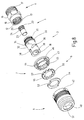
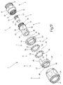
- socket part 1 shows an exploded perspective view a socket part 1 of a ventilation clutch.
- a base body 2 which consists of a front body section 3 and a rear Basic body section 4, a valve closure member 5, an actuating sleeve 6 with its final or End ring 7, an insert 8, a thrust washer 9 and a pressure ring 11.
- the rear body section 4 is a substantially tubular structure with a rotationally symmetrical Passage 12, which has an internal thread at its front end 13 has.
- the passage tapers inside 12 on a ring shoulder 14 recognizable in FIG. 3 to the rear out.
- the rear body section forms on the outside 4 a cylindrical, concentric to the passage 13 Circumferential and sliding surface 15, which at the rear end a hexagon collar 16 passes over.
- To the hexagon collar 16 is followed by an external thread 17, via which the ventilation coupling 1 with a pipe or hose line system is to be connected to a source of compressed air in Connection is established.
- the front base body section 3 is also tubular and has a rotationally symmetrical channel 18 Mistake.
- the channel 18 has up to one again recognizable in FIG Shoulder 19 has a constant cross section. At the Shoulder 19 tapers the diameter of channel 18 abruptly to a smaller diameter, from which the channel 18 is also cylindrical and of constant diameter passes through to a conical surface 21, which acts as a valve seat surface serves. Following the valve seat 21, the channel 18 widens again to a diameter which the passage 12 has at the front end.
- valve closure member 5 In the rear body section 4 facing Section of the channel 18 is the valve closure member 5, which has an essentially cup-shaped shape.
- a cylindrical base projects from a closed base 22 Collar 23, whose outer diameter is dimensioned so that the valve closure member 5 with little play in the rear portion of the channel 18 is slidable.
- the collar 23 At the The transition to the floor 22 is the collar 23 with a series of rectangular passages 24 provided. Between the culverts 24 and the end of the floor pointing away from the viewer 22 there is an annular groove 25 for receiving an O-ring 26, which cooperates with the conical sealing surface.
- a conical spring 27 is provided, which one end supported on the shoulder 14 and the other end against the back of the bottom 22 acts where it is using a Centering approach 28 is radially centered.
- the collar 23 is cylindrical on the outside smooth and also seals with an O-ring 29, which in a groove 31 sits directly on the shoulder surface 19 as shown in Figure 3 connects.
- the front base body section 3 has in its front portion a cylindrical outer peripheral surface 32nd up to a collar 33 a constant cross section Has.
- the collar 33 forms a forward radial Ring shoulder 34.
- An external thread 35 is connected to the collar 33 with which the front body section 3 into the internal thread 13 of the rear body section 4 screwed is.
- An external thread 35 is connected to the collar 33 with which the front body section 3 into the internal thread 13 of the rear body section 4 screwed is.
- In the area of the outer peripheral surface 32 contain two oblique slots 36 which are relative to each other the longitudinal or rotational axis of the base body 2 diametrically opposite.
- the slots 36 each protrude only a short distance into channel 18.
- the two slots 36 are oblique running slits.
- Each of the two slots 36 is by two parallel side surface 37 limited.
- the areas defined by the side walls 37 of the two slots 36 converge towards that front end, as can be seen from the cross section according to FIG. 3 leaves.
- elongated holes 38 are symmetrical between the two slots 36 there are also two elongated holes 38 diametrically opposite one another, whose longitudinal axis parallel to the axis of rotation of the base body 2 lies.
- the side walls of the elongated holes 38 are converged so that the clear width on the Side of the channel 18 is smaller than on the side of the outer peripheral surface 32.
- the exact location of the elongated holes 38 related on the slots 36 results from the following Function Description.
- Actuation sleeve 6 which is a substantially cylindrical Has interior 39, which is at the front end radially tapered on an inwardly projecting collar 41.
- Several latching openings 42 are provided in the rear area, which are distributed equidistantly along the circumference.
- the cylindrical extension 43 fits into the interior 39 and with little play goes at its end remote from the actuating sleeve 6 in an outwardly projecting collar 44.
- the cylindrical tubular extension 43 is on it Inside with a large number of equidistantly distributed ribs 45 provided which delimit a cylinder surface, the Diameter adapted to the diameter of the cylinder surface 15 is.
- the ring 7 is displaceable on the cylinder surface 15.
- the extension 43 carries a row on its peripheral surface of locking lugs 46, which match the locking openings 42, as can be seen from the cross section in FIG. 3.
- the insert 8 is annular or tubular and has a cylindrical inner surface 48 which in a manner to be described as a front support surface serves and is therefore referred to as such below.
- the insert 8 goes in over two diametrically opposed tabs 49, which form cylindrical surfaces towards the outside, which with the Match the inner circumferential surface 39. Between the tabs 49 are two partially annular pressure surfaces 50.
- the pressure surfaces 50 define a plane that is perpendicular to the Longitudinal axis of the base body 2 is aligned.
- the two tabs 49 are also on the inside are delimited by two cylindrical surface sections 51, the Axis of curvature coaxial to the longitudinal axis of the base body 2 is.
- the surfaces 51 serve as rear support or holder surfaces, as described below.
- the rear and front support surfaces 48 and 51 go as can be seen in FIG. 3, into one another via an inclined surface 52 about.
- the inclined surface 52 is from the pressure surfaces 50 slightly cut.
- the pressure ring 11 is a face plate with in the outer peripheral surface existing breakthroughs or recesses 53, which is adapted to the cross-sectional shape of the tabs 49 are so that in the assembled state of the pressure ring 43 opposite the insert or tabs 49 freely displaceable is.
- the pressure ring 11 contains a cylindrical through hole 54, with which the pressure ring 11 with play on the outer peripheral surface 32 is movable.
- the abutment disc 9 is also a thin one Disc with a bore 55, the diameter of the diameter corresponds to the bore 54 and that on your outer peripheral side with a variety of radially protruding ones Extensions 56 is provided, between which channels 57 are formed. The channels 57 sit over the back of the Abutment plate 9 continues.
- the socket part 1 includes two cylindrical ones Locking pins 59 and two retaining balls 61.
- the cylindrical locking pins 59 are in the Oblique slots 36 and are dimensioned in length so that the inner circumferential surface at its maximum radial permissible stroke 39 just touch the actuating sleeve. When installed, they run tangentially to the cylindrical ones Interior 39 and perpendicular to the longitudinal axis of the socket part 2, as can be seen in FIG. 2.
- the holding balls 61 are located in the elongated holes 38, one in each slot. Your diameter is in such a way that, due to the conicity of the Elongated holes 38 can not fall into the channel 18. you Diameter is also greater than the wall thickness of the front Main body section 3 in the area of the elongated holes 38. They are thus either in the channel 18 when they are with the outer peripheral surface 32 are flush, or they protrude the outer peripheral surface 32 when not in it Projecting clearance profile of channel 18.
- the diameter of the holding balls 61 is larger than that Diameter of the locking pins 59. By the difference this diameter intersects the inclined surface 52 the printing surface 50 on.
- the socket part 1 is assembled as follows:
- the front body section 3 is initially with the O-ring 31, then we in the rear part of the channel 18, the valve closure member provided with the O-ring 26 5 inserted with the collar 23 ahead until it occupies the position as shown in FIG. 3. Then will the conical spring 27 in the passage 12 of the rear body section 4 inserted and it becomes the two Basic body sections 3 and 4 by means of the threads 13 and 35 screwed together.
- the outer peripheral surface of the collar 33 goes in the assembled Condition smooth into the outer peripheral surface 15.
- the oblique slots 36 open between the front End of the base body 2 and the annular groove 29 for the O-ring 31, what the figures reveal.
- the compression spring 58 which is at one end on the abutment ring 9 supports, presses the pressure ring 11 with its front plan the end face against the protruding radially outward Sections of the two locking pins 59.
- the Locking pins 59 are at the bottom of the associated one Inclined slot 36 and are with her Axis in a common plane that is perpendicular to the Longitudinal axis of the base body 2 lies.
- the actuating sleeve 6 is from the back the insert 8 inserted until it with the collar surface 47 locked behind the bead of the collar 41.
- the locked one Position can be seen in Figure 3. If the actuating sleeve 6 is prepared in this way, it can plugged onto the base body 2 from the front end become.
- the pressure ring 11 was first in the circumferential direction rotated until the two recesses 53 between the ends of the two locking pins 59 come to rest.
- the retaining balls 61 can then be inserted into the elongated holes 38 are used and there for example by means of a Temporary magnets against falling out of the elongated holes 38 be secured.
- the actuating sleeve 6 can now from the front be pushed onto the pre-assembled base body 2. When pushed on, the tabs 49 slide between the radially protruding ends of the locking pins 59 therethrough and also pass through the recesses 53. As a conclusion the assembly is from the back of the closure or End ring 7 pressed into the actuating sleeve 6, its Lock latch 46 in recesses 42.
- each associated slotted hole 38 they are related on the longitudinal axis of the base body 2 at a height, which corresponds to the height of the locking pins 59 if these at the bottom of the associated inclined slot 37 issue.
- the rest or zero position of the actuating sleeve 6 is when the front of the end ring 7 without Force against the back of the abutment ring 9, while the printing surfaces 50 are stress-free at the ends of the Latch locking pins 59.
- the actuating sleeve can be in the rest or zero position 6 can also be moved backwards. At this after moving backwards, the pressure surfaces press 50 on both sides of the tabs 49 against the protruding ones Ends of the locking pins 59 and move this in the direction of the rear base body section 4. Move due to the oblique orientation of the oblique slots 36 the locking pins 59 inevitably also radially outwards and disappear from the clearance profile of channel 18.
- the retaining balls run in the course of this sliding movement 61 on the two diametrically opposite one another Inclined surfaces 52 and get to the front Support surface 48, from which they are held so that they in protrude the clearance profile of the channel 18.
- Fig. 3 shows the rest position before the introduction of a Plug 65.
- the plug 65 is essentially tubular and, based on its length, has one in the middle Hexagon collar 66 on the back in a connector 67 with external thread 68 and the front End carries a cylindrical tubular extension 69.
- the approach 69 is trapezoidal in cross section Ring groove 71 provided. At its front end at 72 it tapers accordingly to a diameter the diameter of the tapered part of the channel 18.
- a circumferential rib 73 the outer diameter is slightly smaller than the other part of the diameter Channel 18.
- the oblique slots 36 are designed such that the Locking pins 59 run parallel to each other and have a minimal distance from each other that is slightly larger is smaller than the diameter of section 72 than the outer diameter of the rib 73.
- the rib 73 comes with the possibly in the front section of the respective elongated holes 38 lying retaining balls 61 in touch.
- the retaining balls 61 from the support surfaces 48 into the channel 18 held excellent, which brings about the aforementioned touch can come.
- the rib 73 can thus freely the effective area pass the holding balls 61 and meet the in the clearance profile of the channel 18 projecting locking pins 59th
- the plug 65 When pushing in further, the plug 65 also urges the rib 73, the two locking pins 59 against the Effect of the compression spring 58 back, because of the oblique arrangement of the oblique slots 36 also radially after recede outside until the gap between the two Locking pins 59 can pass the rib 73. Once the rib 73 past the locking pins 59 has slipped, the locking pins 59 of the Push ring 11 back into the starting position because the Spring 58 constantly strives for the pressure ring 11 to the front To move end of the socket part 1 out.
- the holding balls 61 Since the wall thickness of the socket part 2 in the area of front end of the channel 18 is smaller than the diameter of the holding balls 61, the holding balls 61 inevitably remain in a room that is on the one hand from the groove 71 and on the other hand from the inclined surface 52 and the rear Support surface 51 is limited. You will be in the area of the rear end of the respective elongated hole 38. In the holding balls 61 are in the said space without pretension.
- the pressure prevailing in the ventilation coupling can not to throw the plug 65 out because the locking pins 59 from the rib 73 against the one in question Wall of the respective oblique slot 36 are pressed. There this wall, as shown, runs at the same time the locking pin 59 is pressed radially inwards.
- the actuating sleeve is used to separate the ventilation coupling 6 towards the rear end of the coupling part 2 as shown in Fig. 5.
- the holding balls 61 hold the Plug 65 in socket part 2 firmly.
- the axial length of the front Support surface 48 is dimensioned so that in the rest position the actuating sleeve 6 the transition to the inclined surface 52 lies beyond the holding ball 61.
- the holding ball 61 is concerned by the rib 73 against the front end of the Elongated hole 38 or the front support surface 48 pressed. This position of the plug 65 can be used as a venting position be designated.
- the valve closure member lies in the venting position 5 with its O-ring seal 26 on the sealing surface 21 and locks those coming from a compressed air source Compressed air.
- the connecting line to the consumer which is connected to the plug 65, through the gap between the end face of the extension 69 and the end face of the cup-shaped collar 23 of the valve closure member 5 vent.
- the outflow of air happens through channels 57 and between the ribs 45 resulting channels of the locking ring 7. This pressure build-up is avoided, the aim would be the actuating sleeve 6 to push forward.
- Plug 65 is removed during venting, i.e. the Pressure drop in the line to the consumer in an intermediate position mechanically positively held.
- the base body 2 free of anti-rotation locks. He's apart from the elongated holes 38 and the oblique slots 36 are rotationally symmetrical Part and can therefore be easily made of metal.
- the actuating sleeve 6 can Injection molded plastic or also a metal part his. In the latter case it is useful if the connection between the actuating sleeve 6 and the end ring 7, instead of a snap connection through a threaded connection will be produced. In the latter case you can choose the end ring 7 are made of metal, or likewise be a molded plastic part.
- the insert 8, the Pressure ring 11 and the abutment disc 9 can also either made of metal or molded from plastic his.
- FIGS. 8-10 Another exemplary embodiment is shown in FIGS. 8-10 of the socket part 2 according to the invention.
- the rear support surfaces 51 are formed on ribs 75, which are integrally formed on the inner peripheral surface 39 are.
- the ribs 75 extend in the longitudinal direction the actuating sleeve 6 according to the length of the support surface 51.
- the front support surface 48 is covered by the Bore wall of the actuating sleeve 6 is formed.
- the printing surfaces 50 are also directly on the inside of the collar 41.
- the assembly corresponds, apart from the not necessary Insert the insert 8, the assembly of the socket part of Fig. 1.
- the operation when inserting of the connector 65 and when uncoupling is as before explained with reference to Figures 3-7.
- the actuating sleeve 6 is somewhat similar the actuating sleeve 6 of the embodiment Fig. 8 insofar as the front support surface 48 and the Inclined surface 52 in one piece directly on the actuating sleeve 6 are executed.
- the tubular insert 8th In contrast to the embodiment of FIG. 1, the tubular insert 8th.
- the assembly of the exemplary embodiment according to FIG. 11 differs basically not from assembly 1 except for the special one Orientation of the thrust washer 11 and the elimination assembling the insert 8.
- the operating sleeve 6 pushed forward.
- This forward movement can Pressure ring 11 as in the previous embodiments do not follow. He will move forward on another through the protruding ends of the locking pins 59 prevented the force exerted by the compression spring 58 take up.
- the actuating sleeve 6 to the front pushed.
- the tabs 49 are slightly as shown Gap, the width of which is smaller than the diameter the holding balls 61.
- the holding balls 61 can be in the Do not jam the gap, but are able to do so far enough to dodge radially outward to pass the rib 73 allow.
- end of the inclined surface 52 that is the smallest radial Has a distance from the longitudinal axis of the base body 2, in the advanced position of the actuating sleeve 6 approximately flush with the front edge of the slot 38 in question.
- the actuating sleeve 6 has the shape of the actuating sleeve of the embodiment 11.
- the pressure ring 11 is like executed in the embodiment of FIG. 1.
- the difference to the previous embodiments is a additional intermediate ring 77 is present to which the tabs 49 are integrally formed.
- the pressure ring 11 lies between the intermediate ring 77 and the locking pins 59.
- the Pressure ring 11 is as in the embodiment of FIG. 1 by the compression spring 58 against the base body 2 protruding ends of the locking pins 59 pressed.
- the bore 78 contained in the pressure ring 77 has a diameter corresponding to the radius of curvature of the rear Support surfaces 51, and is therefore larger than that Circle the through the ground in the outside Hämungen 53 is defined.
- the outside diameter agrees with the clear width of the interior 39 of the actuating sleeve 6 coincides with what the intermediate ring 77 merges with with the tabs 49 in principle in the actuating sleeve 6 can be moved. This is only important in Relation to assembly, during operation and the intermediate ring 77 remains in function with respect to the Actuating sleeve 6 at rest, unless the actuating sleeve 6 is rotated in the circumferential direction.
- a further compression spring 79 provided, which is located on the back of the intermediate ring 77 supports and there for example by means of a centering extension 81 is centered radially. At the other end supports the compression spring 79 on the abutment plate 9 in the same way as the compression spring 58.
- the compression spring 58 protrudes through the bore 78 of the intermediate ring in the assembled state 77 through.
- the assembly is basically the same as in the previously explained exemplary embodiments.
- the support surfaces 48 and 51 and the inclined surface 52 always remain in direct contact with one another.
- the support surface 48 and the inclined surface 52 are an integral part of the actuating sleeve 6, while the rear support surfaces 51 on the tabs 49 of the Intermediate ring 77 are formed. Has the function however, this has no impact.
- front and rear support surfaces 48 and 51 and the inclined surface 52 is in all embodiments just like this in the context of the embodiment 1 is described, or it is from the functional description of the embodiment of FIG. 1 results.
- the actuating sleeve 6 freely rotatable.
- the turning of the actuating sleeve 6 does not transmit any forces to the locking pins 59.
- the rear support surfaces 51 become flush the holding balls 61 held because they are formed on tabs 49 are between the ends of the locking pins 59, which protrude beyond the outer circumferential surface 32 in the circumferential direction be adequately held in the correct position. Since the support surfaces 51 cutouts from cylindrical surfaces are coaxial with the longitudinal axis of the base body 2 are possible slight twists in the circumferential direction to no changed function.
- mushroom-shaped holding body can be used instead of the described holding balls 61 .
- the elongated holes then contain a circumferential shoulder which shows radially outwards and on which the mushroom-shaped Can hold body with his head to keep from falling to prevent in the channel 18.
- the ventilation channels have the shape of grooves 85 and run on a position in the axial direction such that it does not have the effective as front support surfaces for the retaining balls 61 Affect the area.
- the compressed air not only replenishes as quickly as possible can flow out at the front without building up too much pressure, but also as quickly and with high pressure as possible Can reach the end face of the rear locking ring 7, there are further grooves 86 in the tabs 49.
- the grooves 86 which are designed according to the figures, also lie in the area outside the path of movement of the retaining balls 61 lie opposite the tabs 49. The grooves 86 are therefore laterally parallel to the actual rear Support surfaces.
- the pressure ring 11 as a radially feathered disc educated.
- the pressure ring contains in addition to the two Grooves 53 for the tabs 49 further extending in the axial direction narrow grooves or openings 87.
- the locking pins 59th After releasing the plug 65 by pulling it back the actuating sleeve 6, the locking pins 59th also withdrawn and leave the connector 65 free. He is now in the unlocked position as described above held by the balls 61. In the stop position the compressed air flows radially through the slots 36 and 38 outward. First of all, it flows into an axial space the forward through the shoulder 50 or the inclined surface 52 and is limited to the rear by the pressure ring 11.
- the outflowing air can pass through the grooves 86 and 87 and the grooves 57 very quickly and with relatively little Pressure reduction reach the rear locking ring 7, where they exert an axial thrust on the Lock ring 7 exercises.
- This force partially compensates the forward force exerted by the shoulder 50. Since the ventilation channels 85 are included, the after Leading in front becomes the effective shoulder area reduced and on the other hand the pressure build-up is reduced.
- the differential force that is still striving the actuating sleeve can be moved forward this way can be reduced to values that reflect the power of Spring 58 can not overcome.
- the actuating sleeve will due to escaping compressed air, not into the one pushed forward Position pressed, and the connector 65 remains reliable held in the vent position.
- the ventilation channels in the form of grooves 85 and 86 can for example also in the embodiment Fig. 8 can be used.
- Figures 20 and 21 show one such modification of the exemplary embodiment according to FIG. 8.
- the grooves 85 and 86 are immediate formed in the actuating sleeve 6.
- the mode of action is as previously described.
- a ventilation coupling has a base body in which there are two slanted slots that form a channel cut in the body.
- the slanted slots serve the Inclusion of cylindrical locking pins on the ends protrude beyond the body.
- Symmetrical between the oblique slots are distributed in two slots there are retaining balls.
- the elongated holes lead outwards from the mouth area of the slanted slots in the channel to front end of the base body.
- the locking pins are made using a pressure ring and a spring on a rear abutment of the main body supports in the pushed forward Position pressed in which it is tangential through the clearance profile of the canal.
- the radial movement of the retaining balls is determined by the front and rear support surfaces controlled, the different Have a distance from the longitudinal axis of the base body.
- the big radial stroke makes additional relative movements between the support surfaces and thus a movement of the actuating sleeve when inserting of the plug is unnecessary.
Landscapes
- Engineering & Computer Science (AREA)
- General Engineering & Computer Science (AREA)
- Mechanical Engineering (AREA)
- Quick-Acting Or Multi-Walled Pipe Joints (AREA)
Abstract
Description
- Fig. 1
- eine Explosionsdarstellung der wesentlichen Teile eines erfindungsgemäßen Buchsenteils, in einer perspektivischen Darstellung,
- Fig. 2
- den Buchsenteil nach Fig.1, in einem Querschnitt längs der Linie II nach Fig.3,
- Fig. 3-7
- den Buchsenteil nach Fig.1 in einem Längsschnitt, geschnitten längs der Linie 33 nach Figur 2 in Verbindung mit einem Stecker, in unterschiedlichen Betriebsstellungen,
- Fig. 8
- eine Explosionsdarstellung eines zweiten Ausführungsbeispiels des erfindungsgemäßen Buchsenteils,
- Fig. 9
- den Buchsenteil nach Fig. 8, geschnitten längs der Linie IX-IX nach Fig. 8,
- Fig. 10
- den Buchsenteil nach Fig. 8 in einem Längsschnitt, geschnitten längs der Linie X-X nach Fig. 9, in Verbindung mit einem Stecker und in der ungekuppelten Stellung,
- Fig. 11
- ein drittes Ausführungsbeispiel des erfindungsgemäßen Buchsenteils in einer perspektivischen Explosionsdarstellung,
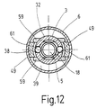
- Fig. 12
- den Buchsenteil nach Fig. 11, geschnitten längs der Linie XI-XI nach Fig. 13,
- Fig. 13
- den Buchsenteil nach Fig. 11 in einem Längsschnitt, geschnitten längs der Linie XII-XII Fig. 12, in Verbindung mit einem Stecker und in der ungekuppelten Stellung,
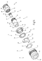
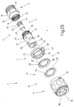
- Fig. 14
- ein viertes Ausführungsbeispiel des erfindungsgemäßen Buchsenteils in einer perspektivischen Explosionsdarstellung,
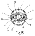
- Fig. 15
- den Buchsenteil nach Fig. 14, geschnitten längs der Linie XV-XV nach Fig. 16,
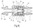
- Fig. 16
- den Buchsenteil nach Fig. 14 in einem Längsschnitt geschnitten längs der Linie XVI-XVI nach Fig. 15 in Verbindung mit einem Stecker und in der ungekuppelten Stellung,
- Fig. 17
- Das erfindungsgemäße Buchsenteil nach Fig. 1 jedoch mit zusätzlichen Entlüftungskanälen, in einer perspektivischen Explosionsdarstellung,
- Fig. 18
- den Einsatz mit den Stützflächen für die Betätigungshülse des Buchsenteils nach Fig. 17, in einer perspektivischen Forderansicht,
- Fig. 19
- den Einsatz nach Fig. 18 in einer perspektivischen Rückansicht,
- Fig. 20
- das Ausführungsbeispiel des Kupplungsteils nach Fig. 8 jedoch mit zusätzlichen Entlüftungskanälen, in einer perspektivischen Explosionsdarstellung, und
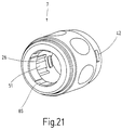
- Fig. 21
- die Betätigungshülse des Buchsenteils nach Fig. 20 in einer vergrößerten perspektivischen Vorderansicht.
Claims (52)
- Buchsenteil (1) einer Entlüftungskupplung für Fluidverbindungen,wobei die Abmessungen derart gestaltet sind,mit einem einen durchgehenden, geraden und rotationssymmetrischen Kanal (18) enthaltenden Grundkörper (2), der von einer Außenumfangsfläche (32) begrenzt ist, auf dessen Außenumfangsfläche (32) eine in axialer Richtung zeigende Schulter (34) ausgebildet ist und der ein vorderes und ein hinteres Ende bildet, wobei von dem vorderen Ende her ein Stecker (65) in den Kanal (18) einführbar ist,mit wenigstens einem ersten Schlitz (36) in dem Grundkörper (2), dessen Lichtraumprofil tangential den Kanal (18) schneidet und dessen Wände (37) parallel zu einer Ebene sind, die schräg zu der Längsachse des Kanals (18) ausgerichtet ist,mit wenigstens einem Verriegelungsstift (59), der sich in dem ersten Schlitz (36) befindet und mit seinen beiden Endabschnitten über die Außenumfangsfläche (32) des Grundkörpers (2) übersteht,mit wenigstens einem Langloch (38), das von der Außenumfangsfläche (32) ausgehend bis zu dem Kanal (18) reicht und dessen Längsachse zu der Längsachse des Kanals (18) parallel ausgerichtet ist,mit wenigstens einem Haltekörper (61), der in dem Langloch (38) enthalten ist und dessen Abmessungen in radialer Richtung bezogen auf den Grundköper (2) größer ist als die Wandstärke des Grundkörpers (2) im Bereich des Langlochs (38),mit einem Druckring (11), der auf dem Grundkörper (2) verschieblich sitzt und mit den Enden des wenigstens einen Verriegelungsstifts (59) zusammenwirkt,mit wenigstens einer Druckfedereinrichtung (58), die zwischen dem Druckring (11) und einem Widerlager (9,34) wirksam ist, um den Druckring (11) in diejenige Richtung vorzuspannen, in der der Verriegelungsstift (59) gegen den Grund des Schlitzes (36) vorgespannt ist,mit einer auf dem Grundkörper (2) angeordneten und auf dem Grundkörper (2) längsverschieblichen Betätigungshülse (6), deren Innenraum in wenigsten einen ersten (41) und einen zweiten (39) Abschnitt gegliedert ist, von denen der erste (41) dem vorderen Ende benachbart ist, und die in ihrem Inneren eine Schulter (50) enthält, die zum Zusammenwirken mit den Enden des wenigstens einen Verriegelungsstifts (59) eingerichtet ist, wobei die Betätigungshülse (6) in eine erste, eine zweite und eine dritte Stellung zu bringen ist,mit einem Widerlagerring (9), der in einem Ringspalt zwischen der Betätigungshülse (6) und dem Grundkörper (2) enthalten und gegenüber beiden verschieblich ist sowie das Widerlager (9,34) für die Federeinrichtung (58) bildet,mit wenigstens einer dem vorderen Ende benachbarten vorderen Stützfläche (48) für den Haltekörper (61),mit wenigstens einer von dem vorderen Ende abliegenden hinteren Stützfläche (51) für den Haltekörper (61),mit wenigstens einer Schrägfläche (52), die sich zwischen der zugehörigen vorderen und der zugehörigen hinteren Stützfläche (48,51) erstreckt, undmit einem in dem Kanal (18) enthaltenen Ventil (5,21), das bei eingeschobenem Stecker (65) von diesem in der geöffneten Stellung gehalten wird,dass die erste Stützfläche (48) einen radialen Abstand aufweist, derart, dass ein an der ersten Stützfläche (48) anliegender Haltekörper (61) in den Kanal (18) hineinragt,dass die zweite Stützfläche (51) einen radialen Abstand aufweist, derart, dass ein an der zweiten Stützfläche (51) anliegender Haltekörper (61) nicht in das Lichtraumprofil des Kanals (18) hineinragt,dass der Haltekörper (61) in derjenigen Lage, in der er in dem Langloch (38) am weitesten von dem vorderen Ende entfernt ist, sich im wesentlichen auf der gleiche Höhe befindet wie der Verriegelungsstift (59), wenn er sich in einer Lage befindet, in der er dem vorderen Ende am nächsten benachbart ist,dass in der Ruhestellung der Betätigungshülse (6) die zweite Stützfläche (51) dem hinteren Ende des Langlochs (38) gegenüber steht und die Schrägfläche (52) von dem hinteren Ende des Langlochs (38) einen Abstand aufweist, derart, dass der Haltekörper (61) mit geringem Spiel auf der Höhe des Verriegelungsstifts (59) gehalten wird.
- Buchsenteil nach Anspruch 1, dadurch gekennzeichnet, dass die Außenumfangsfläche (32) zumindest in einem an dem vorderen Ende beginnenden Abschnitt im wesentlichen rotationssymmetrisch ist.
- Buchsenteil nach Anspruch 1, dadurch gekennzeichnet, dass der Grundkörper (2) aus einem vorderen und einem hinteren Abschnitt (3,4) besteht, die miteinander formschlüssig verbunden sind.
- Buchsenteil nach Anspruch 1, dadurch gekennzeichnet, dass der Kanal (18) ausgehend von seinem vorderen Ende bis hinter den Schlitz (36) zylindrisch mit durchgehend konstantem Querschnitt ist.
- Buchsenteil nach Anspruch 1, dadurch gekennzeichnet, dass zwei Schlitze (36) enthalten sind, die sich bezüglich der Längsachse des Kanals (18) diametral gegenüber liegen und deren Seitenwände Ebenen definieren, die in Richtung auf das vordere Ende konvergieren.
- Buchsenteil nach Anspruch 1, dadurch gekennzeichnet, dass zwei Langlöcher (38) enthalten sind, die sich bezüglich der Längsachse des Kanals (18) diametral gegenüberliegen.
- Buchsenteil nach Anspruch 1, dadurch gekennzeichnet, dass die Weite des Langlochs (18) gemessen rechtwinklig zu dessen Längsachse an der Außenumfangsfläche (32) des Grundkörpers (2) größer ist als auf der Seite des Kanals (18), derart, dass ein in dem Langloch (38) befindlicher Haltekörper (61) daran gehindert ist, das Langloch (38) in Richtung auf den Kanal (18) zu passieren, wobei die Abmessungen derart gewählt sind, dass der Haltekörper (61) in einer Lage, in der er der Längsachse des Kanals (18) am nächsten benachbart ist, in den Kanal (18) hineinragt.
- Buchsenteil nach Anspruch 1, dadurch gekennzeichnet, dass der Haltekörper (61) von einer Kugel gebildet ist.
- Buchsenteil nach Anspruch 1, dadurch gekennzeichnet, dass der Haltekörper die Gestalt eines Pilzes aufweist und dass das Langloch eine umlaufende Schulter enthält.
- Buchsenteil nach Anspruch 1, dadurch gekennzeichnet, dass die Federeinrichtung (58) von lediglich einer einzigen schraubenförmigen Druckfeder (58) gebildet wird, die mit dem Druckring (11) zusammenwirkt.
- Buchsenteil nach Anspruch 1, dadurch gekennzeichnet, dass die Federeinrichtung (58) zwei zueinander konzentrische schraubenförmige Druckfedern (58,79) aufweist, von denen lediglich die radial innen liegende mit dem Druckring (11) zusammenwirkt.
- Buchsenteil nach Anspruch 1, dadurch gekennzeichnet, dass die Betätigungshülse (6) aus Metal besteht.
- Buchsenteil nach Anspruch 1, dadurch gekennzeichnet, dass die Betätigungshülse (6) ein Kunststoffspritzteil ist.
- Buchsenteil nach Anspruch 1, dadurch gekennzeichnet, dass der erste Abschnitt (41) der Betätigungshülse (6) einen geringeren Durchmesser aufweist als der zweite Abschnitt (39).
- Buchsenteil nach Anspruch 1, dadurch gekennzeichnet, dass der Widerlagerring (9) Entlüftungskanäle (57) enthält.
- Buchsenteil nach Anspruch 1, dadurch gekennzeichnet, dass der Widerlagerring (9) ein Kunststoffformteil ist.
- Buchsenteil nach Anspruch 1, dadurch gekennzeichnet, dass sich der Widerlagerring (9) im Ruhezustand an der Schulter (34) des Grundkörpers (2) abstützt.
- Buchsenteil nach Anspruch 1, dadurch gekennzeichnet, dass der Betätigungshülse (6) ein Verschlussring (7) zugeordnet ist.
- Buchsenteil nach Anspruch 18, dadurch gekennzeichnet, dass der Verschlussring (7) mit der Betätigungshülse (6) formschlüssig verbunden ist.
- Buchsenteil nach Anspruch 19, dadurch gekennzeichnet, dass die formschlüssige Verbindung von einer Rastverbindung (42,46) gebildet ist.
- Buchsenteil nach Anspruch 19, dadurch gekennzeichnet, dass die formschlüssige Verbindung von einem Gewinde gebildet ist.
- Buchsenteil nach Anspruch 1, dadurch gekennzeichnet, dass der Verschlussring (7) sich auf jener Seite des Wiederlagers (9) befindet, die von dem vorderen Ende des Grundkörpers (2) abliegt.
- Buchsenteil nach Anspruch 1, dadurch gekennzeichnet, dass der Verschlussring (7) Entlüftungskanäle enthält.
- Buchsenteil nach Anspruch 1, dadurch gekennzeichnet, dass die vordere Stützfläche (48) an der Betätigungshülse (6) ausgebildet ist.
- Buchsenteil nach Anspruch 1, dadurch gekennzeichnet, dass die vordere Stützfläche (48) ein Ausschnitt aus einer Zylinderfläche ist, die zu der Längsachse des Kanals (18) koaxial ist.
- Buchsenteil nach Anspruch 1, dadurch gekennzeichnet, dass die Betätigungshülse (6) einen im Wesentlichen rohrförmigen Einsatz (8) enthält.
- Buchsenteil nach Anspruch 1, dadurch gekennzeichnet, dass der rohrförmig Einsatz (8) in der Betätigungshülse (6) drehbar ist.
- Buchsenteil nach Anspruch 1, dadurch gekennzeichnet, dass die vordere Stützfläche (48) an der Innenseite des rohrförmigen Einsatzes (8) ausgebildet ist.
- Buchsenteil nach Anspruch 1, dadurch gekennzeichnet, dass die Schrägfläche (52) ein Ausschnitt aus einer Kegelmantelfläche ist, die zu der Längsachse des Kanals (18) koaxial ist.
- Buchsenteil nach Anspruch 1, dadurch gekennzeichnet, dass die Schrägfläche (52) in der Betätigungshülse (6) ausgebildet ist.
- Buchsenteil nach Anspruch 1, dadurch gekennzeichnet, dass die Schrägfläche (52) in dem rohrförmigen Einsatz (8) ausgebildet ist.
- Buchsenteil nach Anspruch 1, dadurch gekennzeichnet, dass die hintere Stützfläche (51) ein Ausschnitt aus einer Zylinderfläche ist, die zu der Längsachse des Kanals (18) koaxial ist.
- Buchsenteil nach Anspruch 1, dadurch gekennzeichnet, dass die Breite der hinteren Stützfläche (51) gemessen in Umfangsrichtung des Grundkörpers (2) etwa dem Abstand der Verriegelungsstifte (59) in der Ruhestellung entspricht und dass die zweite Stützfläche (51) einen radialen Abstand von der Längsachse des Grundkörpers (18) aufweist, der kleiner ist als der radiale Abstand, den ein Ende eines Verriegelungsstifts (59) hat.
- Buchsenteil nach Anspruch 1, dadurch gekennzeichnet, dass die hintere Stützfläche (51) in dem rohrförmigen Einsatz (8) der Betätigungshülse (6) ausgebildet ist.
- Buchsenteil nach Anspruch 1, dadurch gekennzeichnet, dass die hintere Stützfläche (51) auf einer Rippe (75) im Inneren der Betätigungshülse (6) ausgebildet ist, die in Längsrichtung verläuft.
- Buchsenteil nach Anspruch 1, dadurch gekennzeichnet, dass die hintere Stützfläche (51) auf einer axial sich erstreckenden Lasche (49) ausgebildet ist, die mit dem Druckring (11) einstückig ist.
- Buchsenteil nach Anspruch 1, dadurch gekennzeichnet, dass die hintere Stützfläche (51) an einer Lasche (49) ausgebildet ist, die mit einem Ring (77) einstückig ist, der sich auf der von dem vorderen Ende abliegenden Seite des Druckrings (11) befindet,
- Buchsenteil nach Anspruch 1, dadurch gekennzeichnet, dass der Druckring (11) zum Durchtritt der Lasche (49) an seiner Außenseite wenigstens einer Ausnehmung (53) aufweist.
- Buchsenteil nach Anspruch 1, dadurch gekennzeichnet, dass zur Betätigung der Verriegelungsstifte (59) Druckflächen (50) unmittelbar in der Betätigungshülse (6) vorgesehen sind.
- Buchsenteil nach Anspruch 1, dadurch gekennzeichnet, dass zur Betätigung der Verriegelungsstifte (59) Druckflächen (50) vorgesehen sind, die an dem Einsatz (8) ausgebildet sind.
- Buchsenteil nach Anspruch 1, dadurch gekennzeichnet, dass wenigstens ein Entlüftungskanal (85,86) vorgesehen ist, durch den zweiten Abschnitt (39) der Betätigungshülse (6) strömungsmäßig mit der Außenatmosphäre verbunden ist.
- Buchsenteil nach Anspruch 1, dadurch gekennzeichnet, dass der Entlüftungskanal (85,86) in der Innenfläche des vorderen Abschnitts (41) der Betätigungshülse (6) als Nut (85) ausgebildet ist.
- Buchsenteil nach Anspruch 24 und 41, dadurch gekennzeichnet, dass der Entlüftungskanal (85,86) neben der vorderen Stützfläche (48) vorzugsweise als Nut (85) ausgebildet ist.
- Buchsenteil nach Anspruch 26 und 41, dadurch gekennzeichnet, dass der Entlüftungskanal (85,86) in dem rohrförmigen Einsatz (8) als Nut (85) ausgebildet ist.
- Buchsenteil nach Anspruch 41, dadurch gekennzeichnet, dass der Entlüftungskanal (86) sich bis zum hinteren Ende der hinteren Stützfläche (51) fortsetzt.
- Buchsenteil nach Anspruch 35 und 45, dadurch gekennzeichnet, dass der Entlüftungskanal (86) sich als Nut neben der hinteren Stützfläche (51) erstreckt.
- Buchsenteil nach Anspruch 35 und 45, dadurch gekennzeichnet, dass der Entlüftungskanal (86) sich als Nut auf der Rippe (75) erstreckt.
- Buchsenteil nach Anspruch 36 und 45, dadurch gekennzeichnet, dass der Entlüftungskanal (86) sich als Nut auf der Lasche (49) erstreckt.
- Buchsenteil (1) einer Entlüftungskupplung für Fluidverbindungen,mit einem einen durchgehenden, geraden und rotationssymmetrischen Kanal (18) enthaltenden Grundkörper (2), der von einer Außenumfangsfläche (32) begrenzt ist und der ein vorderes und ein hinteres Ende bildet, wobei von dem vorderen Ende her ein Stecker (65) in den Kanal (18) einführbar ist,mit einer ersten lösbaren Verriegelungseinrichtung (36,59), die wenigstens eine ersten Schlitz (36) in dem Grundkörper (2) sowie ein darin sitzendes Verriegelungselement (59) enthält und die dazu dient, einen Stecker (65) in dem Buchsenteil (1) in einer Stellung zu verriegeln, in der die Fluidverbindung besteht und nach außen abgedichtet ist,mit einer lösbaren Halteeinrichtung (38,61), die wenigstens einen zweiten Schlitz (38) in dem Grundkörper (2) sowie ein darin sitzendes Halteelement (61) enthält und die dazu dient, einen Stecker (65) in dem Buchsenteil (1) in einer Stellung zu halten, in der die Fluidverbindung unterbrochen ist und eine Entlüftung außen besteht,mit einer auf dem Grundkörper (2) angeordneten und auf dem Grundkörper (2) längsverschieblichen Betätigungshülse (6) zum Betätigen der Verriegelungseinrichtung (36,59) und der Halteeinrichtung (38,61), wobei der Innenraum der Betätigungshülse (6) in wenigsten einen ersten (41) und einen zweiten (39) Abschnitt gegliedert ist, von denen der erste (41) dem vorderen Ende benachbart ist, undmit wenigstens einem Entlüftungskanal (85,86,87), durch den zweiten Abschnitt (39) der Betätigungshülse (6) strömungsmäßig mit der Außenatmosphäre verbunden ist.
- Buchsenteil nach Anspruch 49, dadurch gekennzeichnet, dass der Buchsenteil (1) wenigstens eine dem vorderen Ende benachbarten vorderen Stützfläche (48) für den Haltekörper (61), wenigstens eine von dem vorderen Ende abliegenden hinteren Stützfläche (51) für den Haltekörper (61) und eine Schrägfläche (52) aufweist, die sich zwischen der zugehörigen vorderen und der zugehörigen hinteren Stützfläche (48,51) erstreckt, und dass die vordere Stützfläche (48), die hintere Stützfläche (51) und die Schrägfläche (52) derart gestaltet sind, dass sie mittels der Betätigungshülse (6) relativ zu dem Grundkörper (2) in Längsrichtung desselben veschiebbar sind.
- Buchsenteil nach Anspruch 49, dadurch gekennzeichnet, dass der Entlüftungskanal (85,86) in der Innenfläche der Betätigungshülse (6) als Nut ausgebildet ist.
- Buchsenteil nach Anspruch 49, dadurch gekennzeichnet, dass die Merkmale von einem oder mehreren der Ansprüche 1 bis 40 aufweist.
Priority Applications (1)
| Application Number | Priority Date | Filing Date | Title |
|---|---|---|---|
| EP07005233A EP1793154A3 (de) | 2000-08-22 | 2001-08-10 | Buchsenteil für eine pneumatische Entlüftungskupplung |
Applications Claiming Priority (2)
| Application Number | Priority Date | Filing Date | Title |
|---|---|---|---|
| DE2000140979 DE10040979C1 (de) | 2000-08-22 | 2000-08-22 | Buchsenteil für eine pneumatische Entlüftungskupplung |
| DE10040979 | 2000-08-22 |
Related Child Applications (1)
| Application Number | Title | Priority Date | Filing Date |
|---|---|---|---|
| EP07005233A Division EP1793154A3 (de) | 2000-08-22 | 2001-08-10 | Buchsenteil für eine pneumatische Entlüftungskupplung |
Publications (2)
| Publication Number | Publication Date |
|---|---|
| EP1182391A2 true EP1182391A2 (de) | 2002-02-27 |
| EP1182391A3 EP1182391A3 (de) | 2003-11-12 |
Family
ID=7653251
Family Applications (2)
| Application Number | Title | Priority Date | Filing Date |
|---|---|---|---|
| EP01119315A Withdrawn EP1182391A3 (de) | 2000-08-22 | 2001-08-10 | Buchsenteil für eine pneumatische Entlüftungskupplung |
| EP07005233A Withdrawn EP1793154A3 (de) | 2000-08-22 | 2001-08-10 | Buchsenteil für eine pneumatische Entlüftungskupplung |
Family Applications After (1)
| Application Number | Title | Priority Date | Filing Date |
|---|---|---|---|
| EP07005233A Withdrawn EP1793154A3 (de) | 2000-08-22 | 2001-08-10 | Buchsenteil für eine pneumatische Entlüftungskupplung |
Country Status (2)
| Country | Link |
|---|---|
| EP (2) | EP1182391A3 (de) |
| DE (1) | DE10040979C1 (de) |
Cited By (3)
| Publication number | Priority date | Publication date | Assignee | Title |
|---|---|---|---|---|
| WO2002088591A1 (fr) * | 2001-04-26 | 2002-11-07 | Legris Sa | Dispositif de raccordement auto-obturant et embout pour celui-ci |
| EP1298378A3 (de) * | 2001-09-26 | 2003-11-19 | Rectus GmbH | Buchsenteil mit drehbarer Betätigungshülse |
| EP1248029B1 (de) * | 2001-04-03 | 2005-11-16 | Staubli Faverges | Schnellkupplung für die lösbare Verbindung zweier Rohrleitungen und ihre Verwendung |
Families Citing this family (7)
| Publication number | Priority date | Publication date | Assignee | Title |
|---|---|---|---|---|
| DE10227296B3 (de) * | 2002-06-19 | 2004-01-08 | Rectus Gmbh | Buchsenteil einer Entlüftungskupplung für Fluidverbindungen |
| DE10315340B3 (de) * | 2003-04-03 | 2004-11-25 | Dart Engineering Ag | Buchsenteil einer Entlüftungskupplung für Fluidverbindungen ohne getrennte Fangmittel |
| ITMI20090993A1 (it) * | 2009-06-08 | 2010-12-09 | S G S R L | Dispositivo di innesto ad attacco rapido per tubazioni idrauliche |
| IT1398154B1 (it) * | 2009-06-08 | 2013-02-14 | S G S R L | Dispositivo ad attacco rapido per tubazioni idrauliche |
| CN114084314A (zh) * | 2021-11-23 | 2022-02-25 | 大连海事大学 | 一种用于气胀式海上撤离系统的充气接头 |
| CN114391956A (zh) * | 2022-01-19 | 2022-04-26 | 北京罗森博特科技有限公司 | 快速安装锁紧装置 |
| FR3146185B1 (fr) * | 2023-02-27 | 2025-03-28 | Staubli Sa Ets | Élément femelle de raccord rapide, et raccord rapide associé |
Family Cites Families (3)
| Publication number | Priority date | Publication date | Assignee | Title |
|---|---|---|---|---|
| US4366945A (en) * | 1978-12-20 | 1983-01-04 | Abnox Ag | Hose coupling with double lock |
| DE3445129C2 (de) * | 1984-12-11 | 1986-11-20 | Rectus-Apparatebau Walter Klein Gmbh, 7147 Eberdingen | Entlüftungskupplung |
| FR2786849B1 (fr) * | 1998-12-03 | 2001-01-26 | Staubli Sa Ets | Raccord rapide de securite pour la jonction amovible de canalisations |
-
2000
- 2000-08-22 DE DE2000140979 patent/DE10040979C1/de not_active Expired - Fee Related
-
2001
- 2001-08-10 EP EP01119315A patent/EP1182391A3/de not_active Withdrawn
- 2001-08-10 EP EP07005233A patent/EP1793154A3/de not_active Withdrawn
Non-Patent Citations (1)
| Title |
|---|
| None |
Cited By (4)
| Publication number | Priority date | Publication date | Assignee | Title |
|---|---|---|---|---|
| EP1248029B1 (de) * | 2001-04-03 | 2005-11-16 | Staubli Faverges | Schnellkupplung für die lösbare Verbindung zweier Rohrleitungen und ihre Verwendung |
| WO2002088591A1 (fr) * | 2001-04-26 | 2002-11-07 | Legris Sa | Dispositif de raccordement auto-obturant et embout pour celui-ci |
| US6923428B2 (en) | 2001-04-26 | 2005-08-02 | Legris Sa | Self-closing connecting device and connecting piece therefor |
| EP1298378A3 (de) * | 2001-09-26 | 2003-11-19 | Rectus GmbH | Buchsenteil mit drehbarer Betätigungshülse |
Also Published As
| Publication number | Publication date |
|---|---|
| DE10040979C1 (de) | 2002-02-14 |
| EP1182391A3 (de) | 2003-11-12 |
| EP1793154A3 (de) | 2008-03-05 |
| EP1793154A2 (de) | 2007-06-06 |
Similar Documents
| Publication | Publication Date | Title |
|---|---|---|
| EP0034312B1 (de) | Auch unter Druck kuppelbare Schnellverschlusskupplung | |
| DE1775302C3 (de) | Schlauchkupplung | |
| DE4200625C2 (de) | Hydraulische Kupplung mit Druckausgleich und mit Metalldichtungen | |
| DE69003467T2 (de) | Schnellvervindungs- und Schnellöse-Kupplung. | |
| EP0381069A1 (de) | Kupplungsmuffe für hydraulische Leitungsverbindung | |
| DE4100374A1 (de) | Loesbarer verriegelungsmechanismus | |
| DE10040979C1 (de) | Buchsenteil für eine pneumatische Entlüftungskupplung | |
| EP0278420B1 (de) | Schnellverschlusskupplung für insbesondere Hydraulikleitungen | |
| WO1989007222A1 (fr) | Accouplement de surete enfichable, en particulier pour conduites d'air comprime | |
| EP0184799A2 (de) | Entlüftungskupplung | |
| DE3238410C2 (de) | Auch drucklos kuppelbare Schnellverschlußkupplung für insbesondere Hydraulikleitungen | |
| DE10147505B4 (de) | Buchsenteil mit drehbarer Betätigungshülse | |
| DE3005490C2 (de) | Auch unter Druck kuppelbare Schnellverschlußkupplung | |
| DE3444855C1 (de) | Auch bei unter Druck stehendem Stecker kuppelbare Rohrabreisskupplung fuer insbes. Hydraulikleitungen | |
| DE3015601A1 (de) | Schnellverschlusskupplung fuer insbesondere hydraulikleitungen | |
| EP2103859A1 (de) | Aus Kupplungsteilen bestehende Kupplung | |
| EP1304522B1 (de) | Entlüftungskupplung mit Kraftkompensation an der Betätigungshülse | |
| EP1409911B1 (de) | Entlüftungskupplung mit drehentriegelung | |
| DE29620818U1 (de) | Arretiermechanismus | |
| DE4318840C2 (de) | Kupplung zum Verbinden von Hydraulikleitungen | |
| DE10315340B3 (de) | Buchsenteil einer Entlüftungskupplung für Fluidverbindungen ohne getrennte Fangmittel | |
| DE3039072A1 (de) | Auch unter druck kuppelbare schnellverschlusskupplung | |
| DE102004057917A1 (de) | Kupplung für Atemschutzgeräte | |
| EP1180634A1 (de) | Kupplung für unter Druck stehende Medien | |
| DE102007011322A1 (de) | Fluidische Steckkupplungsvorrichtung |
Legal Events
| Date | Code | Title | Description |
|---|---|---|---|
| PUAI | Public reference made under article 153(3) epc to a published international application that has entered the european phase |
Free format text: ORIGINAL CODE: 0009012 |
|
| AK | Designated contracting states |
Kind code of ref document: A2 Designated state(s): AT BE CH CY DE DK ES FI FR GB GR IE IT LI LU MC NL PT SE TR |
|
| AX | Request for extension of the european patent |
Free format text: AL;LT;LV;MK;RO;SI |
|
| PUAL | Search report despatched |
Free format text: ORIGINAL CODE: 0009013 |
|
| AK | Designated contracting states |
Kind code of ref document: A3 Designated state(s): AT BE CH CY DE DK ES FI FR GB GR IE IT LI LU MC NL PT SE TR |
|
| AX | Request for extension of the european patent |
Extension state: AL LT LV MK RO SI |
|
| 17P | Request for examination filed |
Effective date: 20040403 |
|
| AKX | Designation fees paid |
Designated state(s): AT BE CH CY DE DK ES FI FR GB GR IE IT LI LU MC NL PT SE TR |
|
| 17Q | First examination report despatched |
Effective date: 20050513 |
|
| 17Q | First examination report despatched |
Effective date: 20050513 |
|
| GRAP | Despatch of communication of intention to grant a patent |
Free format text: ORIGINAL CODE: EPIDOSNIGR1 |
|
| STAA | Information on the status of an ep patent application or granted ep patent |
Free format text: STATUS: THE APPLICATION IS DEEMED TO BE WITHDRAWN |
|
| 18D | Application deemed to be withdrawn |
Effective date: 20100302 |