EP1182329A2 - Blade attachment using hollow pins - Google Patents
Blade attachment using hollow pins Download PDFInfo
- Publication number
- EP1182329A2 EP1182329A2 EP01306772A EP01306772A EP1182329A2 EP 1182329 A2 EP1182329 A2 EP 1182329A2 EP 01306772 A EP01306772 A EP 01306772A EP 01306772 A EP01306772 A EP 01306772A EP 1182329 A2 EP1182329 A2 EP 1182329A2
- Authority
- EP
- European Patent Office
- Prior art keywords
- dovetail
- wheel
- bucket
- pin
- projections
- Prior art date
- Legal status (The legal status is an assumption and is not a legal conclusion. Google has not performed a legal analysis and makes no representation as to the accuracy of the status listed.)
- Granted
Links
Images

Classifications
-
- F—MECHANICAL ENGINEERING; LIGHTING; HEATING; WEAPONS; BLASTING
- F01—MACHINES OR ENGINES IN GENERAL; ENGINE PLANTS IN GENERAL; STEAM ENGINES
- F01D—NON-POSITIVE DISPLACEMENT MACHINES OR ENGINES, e.g. STEAM TURBINES
- F01D5/00—Blades; Blade-carrying members; Heating, heat-insulating, cooling or antivibration means on the blades or the members
- F01D5/12—Blades
- F01D5/14—Form or construction
-
- F—MECHANICAL ENGINEERING; LIGHTING; HEATING; WEAPONS; BLASTING
- F01—MACHINES OR ENGINES IN GENERAL; ENGINE PLANTS IN GENERAL; STEAM ENGINES
- F01D—NON-POSITIVE DISPLACEMENT MACHINES OR ENGINES, e.g. STEAM TURBINES
- F01D5/00—Blades; Blade-carrying members; Heating, heat-insulating, cooling or antivibration means on the blades or the members
- F01D5/30—Fixing blades to rotors; Blade roots ; Blade spacers
- F01D5/3053—Fixing blades to rotors; Blade roots ; Blade spacers by means of pins
Definitions
- a new control stage bucket configuration is being developed for application with "dense pack" steam turbine designs.
- a fingerdovetail configuration has been selected for attaching the control stage buckets to the turbine rotor.
- a reverse flow of steam from the aft to the forward side of the control stage turbine wheel is desirable to pressurize a shaft seal located forward of the control stage wheel.
- This reverse flow of steam is typically accomplished by providing steam balance holes either through the turbine wheel, or through the bucket platforms.
- a root seal is provided at the admission side of the control stage bucket to discourage flow from the nozzle-bucket space into the forward wheel space.
- a small level of negative root reaction may be applied to the stage design to increase the pressure at the aft side of the turbine wheel to promote additional reverse flow through the wheel.
- the sealing steam must be fed from the space between the first stage nozzle and bucket. Extracting the steam from this location results in a loss in turbine output and efficiency since the sealing steam flows directly from the nozzle into the shaft seal without extracting any useful work.
- the invention provides a unique, hollow dovetail pin configuration to be applied to this control stage application. More particularly, as an embodiment of the invention, a bore or passage is provided through the center of the pin to form a hollow pin. The pin outside and bore dimensions are selected to provide the required steam flow area while meeting all of the pin structural requirements.
- Another important reason for the reverse flow of steam from the aft to the forward side of the control stage wheel is to provide a flow of cooling steam (i.e., lower temperature steam) to the forward side of the wheel.
- the basic mechanism is that the steam on the aft side of the wheel, having had work extracted by the first stage buckets, is at a lower temperature than the steam in the first stage nozzle to bucket space.
- the resulting reduction in component operating temperature improves material strength levels within the affected rotor body and dovetail regions.
- the hollow pin concept of the invention provides the benefits of this cooling steam to the new control stage design.
- the hollow dovetail pins of the invention is expected to reduce the effort involved in removing or extracting the dovetail pins, and to reduce the potential for damaging the dovetail pin holes during the removal/extraction process.
- the bore in the pins would serve as a pilot hole for extracting the pins using a piloted reamer.
- coolant would be applied within the bore of the dovetail pins to cause the pins to contract in diameter to a point where the pins would break free from the oxide build-up and then could be removed intact.
- hole is to thread an extraction device into the pin bore so that appropriate dis-assembly forces could be applied to the pin.
- the hollow pin concept could be used to provide steam balance holes for the purpose of reducing the pressure drop across the turbine wheel with a resulting reduction in the axial thrust level on the rotor. Also, the hollow pin concept could be used to control secondary flows in the turbine so as to reduce interactions between the primary turbine steam flow and secondary flows within the wheelspace and shaft seal regions. Such control is desirable to obtain optimum levels of turbine efficiency.
- hollow finger dovetail pins embodying the invention for a finger dovetail control stage bucket design maximizes turbine efficiency by feeding the forward shaft seal with steam from the aft side of the control stage wheel, provides a flow of cooling steam to the forward side of the control stage wheel and minimizes the effort involved and potential secondary damage associated with removing or extracting finger dovetail pins after a period of turbine operation.
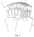
- each bucket 12 has a plurality of bucket dovetail projections 36 with a plurality of bucket dovetail slots 38 defined therebetween, and the wheel has a plurality of generally radial wheel dovetail projections 18 with a plurality of dovetail slots 40 defined therebetween.
- FIGURE 2 shows the sector 10 of FIGURE 1 with one bucket 12 being inserted radially to be engaged with the wheel, so that the bucket dovetail projections 36 are received within respective wheel dovetail slots 40.
- a plurality of dovetail pins 14 are received through respective dovetail pin receiving bores defined by aligned apertures 20, 22 defined in the bucket dovetail projections 36 and the wheel dovetail projections 18, respectively, to complete the connection between the bucket and dovetails.
- FIGURE 3 An exemplary hollow finger dovetail pin 14 is shown in FIGURE 3.
- a bore or passage 24 is defined through the center of the pin 14.
- the outside and the inside dimensions of the finger dovetail pin are selected to maintain the bucket, wheel, and pin operating stresses within determined, allowed stresses. Suitable dimensional determinations may be made by routine experimentation.
- three dovetail pins 14 are preferably applied to each bucket in the row. However, it is contemplated that anywhere from two to six pins could be provided per bucket and at least one of those pins is hollow for fluid flow therethrough. Therefore, the illustrated embodiment is not to be considered limiting in this respect.
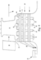
- FIGURE 4 schematically illustrates the function of the pins 14 with respect to providing a reverse flow of steam from the aft side 26 to the forward side 28 of the control stage wheel.
- High pressure steam is accelerated through the first stage nozzle 30 and directed to the bucket 12 where work is extracted to produce turbine power.
- the aerodynamic parameters of this stage are set such that the pressure on the aft side 26 of the wheel is slightly higher than the pressure on the forward side 28 of the wheel 16.
- the total area of the bores or passages 24, which is defined by the area of each bore 24 times the number of hollow pins 14 per bucket 12 times the number of buckets in a row, is selected to produce a sufficient flow to provide most or all of the steam required to feed the forward shaft seal 32.
- a root seal 34 is provided on the forward side of the wheel 16 to discourage the flow of steam from the nozzle/bucket space into the forward wheel space.
- the steam on the aft side 26 of the wheel is also at a lower temperature than the steam in the nozzle to bucket space and thus the axial steam flow through the bucket via the hollow pins provides a source for cooling the forward side of the rotor and dovetail.
Landscapes
- Engineering & Computer Science (AREA)
- Mechanical Engineering (AREA)
- General Engineering & Computer Science (AREA)
- Turbine Rotor Nozzle Sealing (AREA)
Abstract
Description
Claims (10)
- An assembly for locking a generally radially extending bucket (12) to a wheel (16) of a rotor of a turbine, the bucket having a plurality of bucket dovetail projections (36) with a plurality of bucket dovetail slots (38) defined therebetween, and the wheel (16) having a plurality of generally radial wheel dovetail projections (18) with a plurality of dovetail slots (40) defined therebetween, the bucket dovetail projections (36) being received within respective wheel dovetail slots (40), and a plurality of dovetail pins (14) being received through respective dovetail pin bores defined by aligned apertures (20,22) defined in said bucket dovetail projections (36) and said wheel dovetail projections (18), at least one said pin (14) having a bore (24) defined therethrough whereby said pin is hollow and defines a flow path for fluid flow therethrough from one axial side (26) of the wheel to another (28).
- An assembly as in claim 1, wherein there are at least three dovetail pins (14) for securing said bucket (12) with respect to said wheel (16).
- An assembly as in claim 1, wherein there are a plurality of buckets (12) disposed side by side circumferentially of the rotor, each having respective dovetail projections (36) and wherein said dovetail slots (40) of said wheel are defined substantially continuously about the circumference thereof.
- An assembly as in claim 1, wherein each said dovetail pin (14) is hollow for fluid flow therethrough.
- A control stage of a turbine comprising a plurality of generally radially extending buckets (12) secured to a wheel (16) of a rotor of a turbine, said buckets being secured generally side-by-side about the circumference of said wheel, each said bucket having a plurality of bucket dovetail projections (36) with a plurality of bucket dovetail slots (38) defined therebetween, and the wheel (16) having a plurality of generally radial wheel dovetail projections (18) with a plurality of dovetail slots (40) defined therebetween, said wheel dovetail slots (40) extending generally circumferentially of said wheel, the dovetail projections (36) of said buckets being received within respective wheel dovetail slots (40), and a plurality of dovetail pins (14) being received through respective dovetail pin bores defined by aligned apertures (20, 22) defined in said wheel dovetail projections (18) and said dovetail projections (36) of said buckets, respectively, so that a plurality of pins (14) secure each said bucket (12) to said wheel (16), at least one said pin (14) of each said bucket having a bore (24) defined therethrough whereby said pin is hollow and defines a flow path for fluid flow therethrough from one axial side (26) of the wheel to another (28).
- An assembly as in claim 5, wherein there are at least three dovetail pins (14) for securing each said bucket (12) with respect to said wheel (16).
- An assembly as in claim 5, wherein each said dovetail pin (14) is hollow for fluid flow therethrough.
- A method of securing a bucket (12) with respect to a wheel (16) of a rotor, the bucket having a plurality of bucket dovetail projections (36) with a plurality of bucket dovetail slots (38) defined therebetween and the wheel having a plurality of generally radial wheel dovetail projections (18) with a plurality of dovetail slots (40) defined therebetween, the method comprising:assembling the bucket (12) to the wheel by aligning the bucket dovetail projections (36) with respective wheel dovetail slots (40), and radially displacing the bucket so that the bucket dovetail projections are received in the wheel dovetail slots; andinserting a plurality of dovetail pins (14) through respective dovetail pin bores defined by aligned dovetail pin apertures (20, 22) defined in said bucket dovetail projections and said wheel dovetail projections, at least one said pin (14) having a bore (24) defined therethrough whereby said pin is hollow and defines a flow path for fluid flow therethrough from one axial side (26) of the assembled bucket and wheel to another (28).
- A method as in claim 8, wherein said inserting step comprises inserting at least three dovetail pins (14) to securing said bucket (14) with respect to said wheel (16).
- A method as in claim 8, wherein there are a plurality of buckets disposed side by side circumferentially of the rotor, each having respective dovetail projections (36) and wherein said dovetail slots (40) of said wheel (16) are defined substantially continuously about the circumference thereof.
Applications Claiming Priority (2)
| Application Number | Priority Date | Filing Date | Title |
|---|---|---|---|
| US639046 | 2000-08-15 | ||
| US09/639,046 US6364613B1 (en) | 2000-08-15 | 2000-08-15 | Hollow finger dovetail pin and method of bucket attachment using the same |
Publications (3)
| Publication Number | Publication Date |
|---|---|
| EP1182329A2 true EP1182329A2 (en) | 2002-02-27 |
| EP1182329A3 EP1182329A3 (en) | 2003-12-10 |
| EP1182329B1 EP1182329B1 (en) | 2007-04-11 |
Family
ID=24562510
Family Applications (1)
| Application Number | Title | Priority Date | Filing Date |
|---|---|---|---|
| EP01306772A Expired - Lifetime EP1182329B1 (en) | 2000-08-15 | 2001-08-08 | Blade attachment using hollow pins |
Country Status (5)
| Country | Link |
|---|---|
| US (1) | US6364613B1 (en) |
| EP (1) | EP1182329B1 (en) |
| JP (1) | JP2002161704A (en) |
| KR (1) | KR100747924B1 (en) |
| DE (1) | DE60127774T2 (en) |
Cited By (3)
| Publication number | Priority date | Publication date | Assignee | Title |
|---|---|---|---|---|
| WO2008083889A1 (en) * | 2007-01-08 | 2008-07-17 | Alstom Technology Ltd | Method and device for pin removal in a confined space |
| EP3643878A3 (en) * | 2018-10-18 | 2020-07-08 | United Technologies Corporation | Pinned airfoil for gas turbine engines |
| EP3643880A3 (en) * | 2018-10-18 | 2020-08-12 | United Technologies Corporation | Rotor assembly with active damping for gas turbine engines |
Families Citing this family (20)
| Publication number | Priority date | Publication date | Assignee | Title |
|---|---|---|---|---|
| US6840740B2 (en) * | 2002-12-06 | 2005-01-11 | General Electric Company | Bucket dovetail design for turbine rotors |
| DE102004051116A1 (en) * | 2004-10-20 | 2006-04-27 | Mtu Aero Engines Gmbh | Rotor of a turbomachine, in particular gas turbine rotor |
| US7134841B2 (en) * | 2004-11-12 | 2006-11-14 | General Electric Company | Device for optimizing and adjustment of steam balance hole area |
| US7635250B2 (en) * | 2006-03-22 | 2009-12-22 | General Electric Company | Apparatus and method for controlling leakage in steam turbines |
| US8105032B2 (en) * | 2008-02-04 | 2012-01-31 | General Electric Company | Systems and methods for internally cooling a wheel of a steam turbine |
| US8096748B2 (en) * | 2008-05-15 | 2012-01-17 | General Electric Company | Apparatus and method for double flow turbine first stage cooling |
| DE102009013348A1 (en) * | 2009-03-16 | 2010-09-23 | Man Turbo Ag | Device and method for connecting a blade to a rotor shaft of a turbomachine |
| US8439635B2 (en) * | 2009-05-11 | 2013-05-14 | Rolls-Royce Corporation | Apparatus and method for locking a composite component |
| US8246305B2 (en) * | 2009-10-01 | 2012-08-21 | Pratt & Whitney Canada Corp. | Gas turbine engine balancing |
| US8414252B2 (en) * | 2010-01-04 | 2013-04-09 | General Electric Company | Method and apparatus for double flow turbine first stage cooling |
| KR101168512B1 (en) | 2010-09-29 | 2012-07-27 | 한국전력공사 | Balde Stucture for Steam Turbine and The Pin |
| JP2012251503A (en) * | 2011-06-03 | 2012-12-20 | Hitachi Ltd | Steam turbine |
| JP5538468B2 (en) * | 2012-03-30 | 2014-07-02 | 株式会社日立製作所 | Method of machining pin joint of turbine rotor blade and turbine rotor, and turbine rotor blade |
| FR2990462B1 (en) * | 2012-05-14 | 2014-05-30 | Snecma | DEVICE FOR ATTACHING AUBES TO A TURBOMACHINE ROTOR DISC |
| JP5951534B2 (en) * | 2013-03-13 | 2016-07-13 | 株式会社東芝 | Steam turbine |
| KR101529532B1 (en) * | 2013-10-16 | 2015-06-29 | 두산중공업 주식회사 | Steam turbine |
| KR101647250B1 (en) * | 2015-02-05 | 2016-08-09 | 두산중공업 주식회사 | Axial locking device of bucket |
| US11441440B2 (en) * | 2020-04-27 | 2022-09-13 | Raytheon Technologies Corporation | Rotor assembly |
| US20240003317A1 (en) * | 2022-06-29 | 2024-01-04 | Whisper Aero Inc. | Propulsor Fan |
| US12000308B2 (en) | 2022-08-23 | 2024-06-04 | General Electric Company | Rotor blade assemblies for turbine engines |
Family Cites Families (22)
| Publication number | Priority date | Publication date | Assignee | Title |
|---|---|---|---|---|
| GB630395A (en) * | 1951-05-07 | 1949-10-12 | Joseph Atkinson | Improvements in or related to discs, rotors or stators for turbines or compressors |
| US2790620A (en) * | 1952-07-09 | 1957-04-30 | Gen Electric | Multiple finger dovetail attachment for turbine bucket |
| FR1234275A (en) * | 1959-05-14 | 1960-10-17 | Westinghouse Electric Corp | Apparatus using elastic fluid |
| FR1275542A (en) * | 1960-09-30 | 1961-11-10 | Alsthom Cgee | Improvement in fixing or stop devices |
| US3189320A (en) * | 1963-04-29 | 1965-06-15 | Westinghouse Electric Corp | Method of cooling turbine rotors and discs |
| US4047840A (en) | 1975-05-29 | 1977-09-13 | The United States Of America As Represented By The Administrator Of The National Aeronautics And Space Administration | Impact absorbing blade mounts for variable pitch blades |
| JPS54130711A (en) * | 1978-03-31 | 1979-10-11 | Toshiba Corp | Turbine moving vane |
| JPS5576407U (en) * | 1978-11-14 | 1980-05-26 | ||
| US4265595A (en) | 1979-01-02 | 1981-05-05 | General Electric Company | Turbomachinery blade retaining assembly |
| JPS55159366A (en) * | 1979-05-25 | 1980-12-11 | Hitachi Ltd | Shaft seal device for axial flow machine |
| JPS6137762Y2 (en) * | 1981-04-07 | 1986-11-01 | ||
| US4460316A (en) * | 1982-12-29 | 1984-07-17 | Westinghouse Electric Corp. | Blade group with pinned root |
| DE3310396A1 (en) * | 1983-03-18 | 1984-09-20 | Kraftwerk Union AG, 4330 Mülheim | MD STEAM TURBINE IN SINGLE-FLOW CONSTRUCTION FOR A HIGH-TEMPERATURE STEAM TURBINE SYSTEM WITH INTERMEDIATE HEATING |
| US4509265A (en) | 1983-03-21 | 1985-04-09 | General Electric Company | Turbine blade measurement |
| JPS62225703A (en) * | 1986-03-28 | 1987-10-03 | Toshiba Corp | Steam turbine |
| US5022824A (en) * | 1988-10-07 | 1991-06-11 | United Technologies Corporation | Pinned airfoil propeller blade |
| JPH0356801U (en) * | 1989-10-03 | 1991-05-31 | ||
| US5062769A (en) * | 1989-11-22 | 1991-11-05 | Ortolano Ralph J | Connector for turbine element |
| US5368444A (en) | 1993-08-30 | 1994-11-29 | General Electric Company | Anti-fretting blade retention means |
| US5388962A (en) * | 1993-10-15 | 1995-02-14 | General Electric Company | Turbine rotor disk post cooling system |
| JPH09242502A (en) * | 1996-03-01 | 1997-09-16 | Mitsubishi Heavy Ind Ltd | Steam turbine |
| US5713721A (en) | 1996-05-09 | 1998-02-03 | General Electric Co. | Retention system for the blades of a rotary machine |
-
2000
- 2000-08-15 US US09/639,046 patent/US6364613B1/en not_active Expired - Fee Related
-
2001
- 2001-08-08 DE DE60127774T patent/DE60127774T2/en not_active Expired - Lifetime
- 2001-08-08 EP EP01306772A patent/EP1182329B1/en not_active Expired - Lifetime
- 2001-08-14 KR KR1020010048882A patent/KR100747924B1/en not_active Expired - Fee Related
- 2001-08-14 JP JP2001245828A patent/JP2002161704A/en active Pending
Cited By (8)
| Publication number | Priority date | Publication date | Assignee | Title |
|---|---|---|---|---|
| WO2008083889A1 (en) * | 2007-01-08 | 2008-07-17 | Alstom Technology Ltd | Method and device for pin removal in a confined space |
| US7628678B2 (en) | 2007-01-08 | 2009-12-08 | Alstom Technology Ltd | Method and device for pin removal in a confined space |
| US8235772B2 (en) | 2007-01-08 | 2012-08-07 | Alstom Technology Ltd | Method and device for pin removal in a confined space |
| EP3643878A3 (en) * | 2018-10-18 | 2020-07-08 | United Technologies Corporation | Pinned airfoil for gas turbine engines |
| EP3643880A3 (en) * | 2018-10-18 | 2020-08-12 | United Technologies Corporation | Rotor assembly with active damping for gas turbine engines |
| US11136888B2 (en) | 2018-10-18 | 2021-10-05 | Raytheon Technologies Corporation | Rotor assembly with active damping for gas turbine engines |
| US11306601B2 (en) | 2018-10-18 | 2022-04-19 | Raytheon Technologies Corporation | Pinned airfoil for gas turbine engines |
| EP4095350A1 (en) * | 2018-10-18 | 2022-11-30 | Raytheon Technologies Corporation | Pinned airfoil for gas turbine engines |
Also Published As
| Publication number | Publication date |
|---|---|
| JP2002161704A (en) | 2002-06-07 |
| DE60127774T2 (en) | 2008-01-03 |
| US6364613B1 (en) | 2002-04-02 |
| KR20020013803A (en) | 2002-02-21 |
| KR100747924B1 (en) | 2007-08-08 |
| DE60127774D1 (en) | 2007-05-24 |
| EP1182329B1 (en) | 2007-04-11 |
| EP1182329A3 (en) | 2003-12-10 |
Similar Documents
| Publication | Publication Date | Title |
|---|---|---|
| US6364613B1 (en) | Hollow finger dovetail pin and method of bucket attachment using the same | |
| US8162617B1 (en) | Turbine blade with spar and shell | |
| EP2372090B1 (en) | Apparatus for cooling a bucket assembly | |
| EP2612997B1 (en) | Composite blade assembly, corresponding turbine rotor wheel and assembly method | |
| US6511294B1 (en) | Reduced-stress compressor blisk flowpath | |
| US6361277B1 (en) | Methods and apparatus for directing airflow to a compressor bore | |
| EP1088963B1 (en) | Method and apparatus for purging turbine wheel cavities | |
| EP3184739B1 (en) | Multi-wall blade with cooling circuit | |
| US20040179936A1 (en) | Tube-type vortex reducer with retaining ring | |
| JP2005307981A (en) | Method and equipment for assembling gas turbine engine rotor assembly | |
| CA2657262A1 (en) | Multi-cast turbine airfoils and method for making same | |
| CN107035419B (en) | Platform Core Feed Cooling System for Multi-Walled Blades | |
| US6893224B2 (en) | Methods and apparatus for assembling turbine engines | |
| EP3163022A1 (en) | Turbine bucket having cooling passageway in the shroud | |
| US20090047128A1 (en) | Fully Bladed Closure For Tangential Entry Round Skirt Dovetails | |
| US6832892B2 (en) | Sealing of steam turbine bucket hook leakages using a braided rope seal | |
| CN100359136C (en) | Shroud for turbine blade and method of assembly thereof | |
| CA2265164C (en) | Removal of cooling air on the housing side of a diffuser of a compressor stage of gas turbines | |
| US20040120817A1 (en) | Methods and apparatus for assembling turbine engines | |
| EP3115555B1 (en) | Integrally bladed rotor portion, corresponding hybrid rotor and gas turbine engine | |
| KR20080018821A (en) | Method and apparatus for manufacturing rotor for steam turbine | |
| EP2143885B1 (en) | Gas assisted turbine seal | |
| JP2005195021A (en) | Low weight control stage for high temperature steam turbines. | |
| US7497658B2 (en) | Stacked reaction steam turbine stator assembly | |
| EP1965028B1 (en) | Apparatus for assembling blade shims |
Legal Events
| Date | Code | Title | Description |
|---|---|---|---|
| PUAI | Public reference made under article 153(3) epc to a published international application that has entered the european phase |
Free format text: ORIGINAL CODE: 0009012 |
|
| AK | Designated contracting states |
Kind code of ref document: A2 Designated state(s): AT BE CH CY DE DK ES FI FR GB GR IE IT LI LU MC NL PT SE TR |
|
| AX | Request for extension of the european patent |
Free format text: AL;LT;LV;MK;RO;SI |
|
| PUAL | Search report despatched |
Free format text: ORIGINAL CODE: 0009013 |
|
| AK | Designated contracting states |
Kind code of ref document: A3 Designated state(s): AT BE CH CY DE DK ES FI FR GB GR IE IT LI LU MC NL PT SE TR |
|
| AX | Request for extension of the european patent |
Extension state: AL LT LV MK RO SI |
|
| 17P | Request for examination filed |
Effective date: 20040611 |
|
| AKX | Designation fees paid |
Designated state(s): DE FR GB |
|
| 17Q | First examination report despatched |
Effective date: 20040812 |
|
| GRAP | Despatch of communication of intention to grant a patent |
Free format text: ORIGINAL CODE: EPIDOSNIGR1 |
|
| GRAS | Grant fee paid |
Free format text: ORIGINAL CODE: EPIDOSNIGR3 |
|
| GRAA | (expected) grant |
Free format text: ORIGINAL CODE: 0009210 |
|
| AK | Designated contracting states |
Kind code of ref document: B1 Designated state(s): DE FR GB |
|
| REG | Reference to a national code |
Ref country code: GB Ref legal event code: FG4D |
|
| REF | Corresponds to: |
Ref document number: 60127774 Country of ref document: DE Date of ref document: 20070524 Kind code of ref document: P |
|
| ET | Fr: translation filed | ||
| PLBE | No opposition filed within time limit |
Free format text: ORIGINAL CODE: 0009261 |
|
| STAA | Information on the status of an ep patent application or granted ep patent |
Free format text: STATUS: NO OPPOSITION FILED WITHIN TIME LIMIT |
|
| 26N | No opposition filed |
Effective date: 20080114 |
|
| PGFP | Annual fee paid to national office [announced via postgrant information from national office to epo] |
Ref country code: FR Payment date: 20090817 Year of fee payment: 9 |
|
| PGFP | Annual fee paid to national office [announced via postgrant information from national office to epo] |
Ref country code: GB Payment date: 20090825 Year of fee payment: 9 |
|
| PGFP | Annual fee paid to national office [announced via postgrant information from national office to epo] |
Ref country code: DE Payment date: 20090827 Year of fee payment: 9 |
|
| GBPC | Gb: european patent ceased through non-payment of renewal fee |
Effective date: 20100808 |
|
| REG | Reference to a national code |
Ref country code: FR Ref legal event code: ST Effective date: 20110502 |
|
| REG | Reference to a national code |
Ref country code: DE Ref legal event code: R119 Ref document number: 60127774 Country of ref document: DE Effective date: 20110301 |
|
| PG25 | Lapsed in a contracting state [announced via postgrant information from national office to epo] |
Ref country code: DE Free format text: LAPSE BECAUSE OF NON-PAYMENT OF DUE FEES Effective date: 20110301 Ref country code: FR Free format text: LAPSE BECAUSE OF NON-PAYMENT OF DUE FEES Effective date: 20100831 |
|
| PG25 | Lapsed in a contracting state [announced via postgrant information from national office to epo] |
Ref country code: GB Free format text: LAPSE BECAUSE OF NON-PAYMENT OF DUE FEES Effective date: 20100808 |