EP1182323A1 - Multi-directional cutters for bi-center drillout bits - Google Patents
Multi-directional cutters for bi-center drillout bits Download PDFInfo
- Publication number
- EP1182323A1 EP1182323A1 EP01305833A EP01305833A EP1182323A1 EP 1182323 A1 EP1182323 A1 EP 1182323A1 EP 01305833 A EP01305833 A EP 01305833A EP 01305833 A EP01305833 A EP 01305833A EP 1182323 A1 EP1182323 A1 EP 1182323A1
- Authority
- EP
- European Patent Office
- Prior art keywords
- rotation
- bit
- region
- centre
- center
- Prior art date
- Legal status (The legal status is an assumption and is not a legal conclusion. Google has not performed a legal analysis and makes no representation as to the accuracy of the status listed.)
- Granted
Links
Images




Classifications
-
- E—FIXED CONSTRUCTIONS
- E21—EARTH OR ROCK DRILLING; MINING
- E21B—EARTH OR ROCK DRILLING; OBTAINING OIL, GAS, WATER, SOLUBLE OR MELTABLE MATERIALS OR A SLURRY OF MINERALS FROM WELLS
- E21B10/00—Drill bits
- E21B10/26—Drill bits with leading portion, i.e. drill bits with a pilot cutter; Drill bits for enlarging the borehole, e.g. reamers
- E21B10/265—Bi-center drill bits, i.e. an integral bit and eccentric reamer used to simultaneously drill and underream the hole
-
- E—FIXED CONSTRUCTIONS
- E21—EARTH OR ROCK DRILLING; MINING
- E21B—EARTH OR ROCK DRILLING; OBTAINING OIL, GAS, WATER, SOLUBLE OR MELTABLE MATERIALS OR A SLURRY OF MINERALS FROM WELLS
- E21B10/00—Drill bits
- E21B10/46—Drill bits characterised by wear resisting parts, e.g. diamond inserts
- E21B10/56—Button-type inserts
- E21B10/567—Button-type inserts with preformed cutting elements mounted on a distinct support, e.g. polycrystalline inserts
- E21B10/5673—Button-type inserts with preformed cutting elements mounted on a distinct support, e.g. polycrystalline inserts having a non planar or non circular cutting face
-
- E—FIXED CONSTRUCTIONS
- E21—EARTH OR ROCK DRILLING; MINING
- E21B—EARTH OR ROCK DRILLING; OBTAINING OIL, GAS, WATER, SOLUBLE OR MELTABLE MATERIALS OR A SLURRY OF MINERALS FROM WELLS
- E21B10/00—Drill bits
- E21B10/46—Drill bits characterised by wear resisting parts, e.g. diamond inserts
- E21B10/56—Button-type inserts
- E21B10/567—Button-type inserts with preformed cutting elements mounted on a distinct support, e.g. polycrystalline inserts
- E21B10/5676—Button-type inserts with preformed cutting elements mounted on a distinct support, e.g. polycrystalline inserts having a cutting face with different segments, e.g. mosaic-type inserts
Definitions
- the present invention relates generally to drill bits, and, more particularly, to a multi-directional cutters for a fixed cutter, drillout bi-center bit.
- Drill bits used to form these boreholes are generally known as bi-center type drill bits.
- Bi-center drill bits are well known in the drilling industry. Various types of bi-center drill bits are described in U.S. Patents Nos. 1,587,266, 1,758,773, 2,074,951, 2,953,354, 3,367,430, 4,408,669, 4,440,244, 4,635,738, 5,040,621, 5,052,503, 5,165,494, 5,678,644 and European Patent Application 0,058,061 all herein incorporated by reference.
- Modern bi-center drill bits are typically used in difficult drilling applications where the earth formations are badly fractured, where there is hole swelling, where the borehole has a tendency to become spiraled, or in other situations where an oversize hole is desirable.
- the top portion of the well bore is often stabilized by setting and cementing casing.
- the cement, shoe, float, and related cementing hardware are then typically drilled out of the casing by a drill bit that is run into the casing for this purpose. Once the cement and related hardware are drilled out, the drill-out bit is tripped out of the hole and a bi-center drill bit is run back into the borehole. Drilling then proceeds with the bi-center drill bit, which drills a hole into the formation below the casing with a diameter that is greater than the inside diameter of the casing.
- the casing tends to be damaged by the gauge cutting elements mounted on the bi-center drill bit because inside the casing the pilot section of the bit is forced to orbit about its center, causing the gauge cutters to engage the casing.
- the forced orbiting action of the pilot section can also cause damage to the cutters on the leading face of the bi-center drill bit.
- the cutting elements have cutting faces which are precisely oriented relative to the direction of travel of the cutter through the formation being drilled.
- cutters located in an area generally between the passthrough center and the drilling center of the bit face of drillout bi-center bits experience two different directions of travel as they drill. One direction of travel occurs when the bit is drilling out, and the other direction of travel occurs when the bit is drilling the full diameter borehole.
- the cutters which lie in line between the two centers experience exactly opposite directions of travel.
- the present invention is directed to overcoming, or at least reducing the effects of, one or more of the problems set forth above.
- a drillout bi-center drill bit comprising a bit body with a first end adapted to be detachably secured to a drill string, a pilot section on a second, opposite end of the bit body and a reamer section intermediate the first and second ends.
- a first drilling center of rotation of the pilot section and a second passthrough center of rotation of the pilot section spaced apart from the first center of rotation by a non-zero distance D.
- a cutting element is fixed on the bit body within the third region.
- the cutting element has a first cutting face generally oriented perpendicular to the direction of travel of the cutting element about first center of rotation of the pilot section and a second cutting face generally oriented perpendicular to the direction of travel of the cutting element about the second center of rotation.
- a drillout bi-center drill bit comprising a bit body with a longitudinal axis and a first end adapted to be detachably secured to a drill string, a pilot section on a second, opposite end of the bit body and a reamer section intermediate the first and second ends.
- a first drilling center of rotation of the pilot section and a second passthrough center of rotation of the pilot section spaced apart from the first center of rotation by a non-zero distance D.
- first region of the pilot section centered about the first center of rotation having a radius D
- second region of the pilot section centered about the second center of rotation having a radius D
- third region of the pilot section formed by the intersection of the first region and the second region.
- first cutters in the third region, with superhard cutting faces generally oriented perpendicular to the direction of travel of the cutting element about the first center of rotation, projecting a distance from the bit body.
- At least one second cutter is fixed on the bit body within the third region and projecting a distance from the bit body greater than the projection of the first cutters, with a cutting face oriented generally perpendicular to the direction of travel of the second cutter about the second center of rotation.
- a drillout bi-center drill bit 10 having multi-directional cutters is shown in accordance with one embodiment of the present invention.
- the drillout bi-center drill bit 10 has a longitudinal axis 11 upon which the drill bit 10 rotates, and a bit body 12 with a first end 14 adapted to be secured to a drill string (not shown) for driving the drill bit 10.
- threads 16 may be used for coupling the drill bit 10 to the drill string.
- a reamer section shown generally by numeral 20, is intermediate the first end 14 and the pilot section 18 of the bi-center drill bit 10.
- the bit body 12 While in operation, the bit body 12 is rotated via the drill string by some external means while the drillout bi-center drill bit 10 is forced into the material being drilled.
- the rotation under load causes cutting elements 24 at the exposed at the cutting face 17 to penetrate into the drilled material and remove the material in a scraping and/or gouging fashion.
- the bit body 12 includes internal passaging (not shown) that allows pressurized drilling fluid to be supplied from the drilling surface to a plurality of nozzle orifices 22. These nozzle orifices 22 discharge the drilling fluid to clean and cool the cutting elements 24 as they engage the material being drilled. The drilling fluid also functions to transport the drilled material to the surface for disposal.
- the pilot section 18 may have a section with at least one fluid passage 26 provided for return flow of the drilling fluid. There also may be other fluid passages 26 provided in the reamer section 20 of the drillout bi-center drill bit 10 as well.
- FIGS 2B and 2C side view perspectives of the drillout bi-center drill bit 10 of the present invention are shown.
- One important characteristic of the drillout bi-center drill bit 10 is its ability to drill a borehole 11 into the earth 13 with a gauge drilling diameter larger than the inside diameter of the casing 15, or pipe or other type of conductor the bit 10 passes through, which is shown in Figure 2C.
- drillout bi-center drill bit 10 Another important characteristic of the of the drillout bi-center drill bit 10 is its ability to drill out cement 17 (and related hardware, not shown) inside the casing 15 as shown in Figure 2B without causing damage to the casing 15 or the cutting elements 24 of the drill bit 10.
- FIG. 3 an end view of a drillout bi-center drill bit 10 of the present invention is shown.
- the gauge drilling diameter as indicated by the circle 28, is generated by radius R1 from a first center of rotation 30 of the pilot section 18.
- the circular portion of the pilot section 18 will be concentric with the diameter 28.
- the cutting elements 24 on the portion of the reamer section 20 radially furthest from the first center of rotation 30 actually drill the gauge drilling diameter of the borehole 11, as indicated at numeral 31.
- the reamer section 20 is formed eccentrically of the pilot section 18, so only a portion of the wall of the borehole 11 is in contact with the cutting elements 24, which cut the final gauge of the borehole 11 at any given time during operation.
- the drillout bi-center drill bit 10 also has a pass through diameter, as indicated by the circle 32, generated by radius R2 from a second center of rotation 34 of the pilot section 18.
- the shortest linear distance at the face of the bit between the centers of rotation 30, 34 is indicated as D.
- the second center of rotation 34 is on the centerline of the smallest cylinder that may be fitted about the drillout bi-center drill bit 10.
- the pass through diameter that is indicated by circle 32 must be smaller than the inside diameter of the casing 15 that the drillout bi-center drill bit 10 must pass through.
- the cutting elements 24 must be oriented on the pilot section 18 in a known manner with respect to the direction of scraping through the material being drilled. This is no problem for bi-center drill bits that do not drill the cement and related hardware out of the casing. However, when a drillout bi-center drill bit is drilling the cement and related hardware in the casing, some of the cutting elements 24 may be subjected to reverse scraping while rotating about the second center of rotation 34. Reverse scraping often causes rapid degradation of the cutting elements 24, and must be avoided.
- the cutting elements 24 are typically polycrystalline diamond compact cutters or PDC.
- a PDC is typically comprised of a facing table of diamond or other superhard substance bonded to a less hard substrate material, typically formed of but not limited to, tungsten carbide.
- the PDC is then often attached by a method known as long substrate bonding to a post or cylinder for insertion into the bit body 12.
- This PDC type of cutting element 24 is particularly sensitive to reverse scraping because loading from reverse scraping can easily destroy both the diamond table bonding and the long substrate bonding.
- the cutting elements are typically configured with a single cutting surface, where the cutting surface is properly oriented to cut through material being drilled when the drill bit rotates around a first center of rotation, such as center of rotation 30, for example.
- a first center of rotation such as center of rotation 30, for example.
- the drillout bi-center drill bit 10 rotates around a second center of rotation, such as center of rotation 34, for example, the cutting surface of the cutting element is not properly oriented to optimally cut through the drilled material. That is, when the cutting element is configured with this single cutting surface, the drill bit is optimally utilized while drilling around the first center of rotation, but is not optimally positioned to cut material when the drill bit rotates around a second center of rotation.
- the cutting element will undesirably wear at a faster rate when the drill bit is rotating around the center of rotation where the single cutting surface of the cutting element is not optimally positioned to cut material.
- the life of the drill bit is undesirably shortened.
- the distance D is the shortest linear distance between center of rotation 30 and center of rotation 34.
- a first region 56 of the pilot section 18, centered about the first center of rotation 30, has a radius D.
- a third region 60 of the pilot section 18 is formed by the intersection of the first region 56 and the second region 58. This iris shaped third region 60 is the critical area where reverse cutter scraping is possible.
- FIG 4B a diagrammatic view of the positions of some of the cutting elements of a drillout bi-center drill bit similar to that of Figure 4A is shown.
- Three cutting elements 72, 74, 76 ( Figures 5-7) of the present invention are shown in the iris shaped third region 60 between the drilling center of rotation 30 and the passthrough center of rotation 34.
- Cutter 72 has two cutting faces 78, 80.
- cutting face 80 of cutter 72 is properly oriented for cutting along the path indicated by arrow 82.
- Cutting face 80 is generally oriented perpendicular to the direction of travel of the cutter 72 in this operating mode which is parallel to dashed line 86 passing through about the drilling center of rotation 30.
- cutting face 78 of cutter 72 is properly oriented for cutting along the path indicated by arrow 84.
- Cutting face 78 is generally oriented perpendicular to the direction of travel of the cutter 72 in this operating mode which is parallel to dashed line 88 passing through about the passthrough center of rotation 34
- Cutter 72 may be formed of any material suitable for drilling earth formations. Since the wear rate of cutting elements near the center of the bit is generally low, cemented tungsten carbide may be suitable. It is understood that during drillout operation, only a small amount of wear is likely to occur on cutting face 78 of cutter 72. It would be expected that much more wear would occur on face 80 when the bit is drilling into the earth. If the wear rates are unacceptably high, the cutter 72 may be formed of an infiltrated material comprising metallic powders such as tungsten carbide mixed with diamond particles and a binder.
- Cutter 74 operates in a manner similar to cutter 72, although as described later, cutter 74 is intended for much more abrasive drilling than cutter 72.
- Cutter 74 has two cutting faces 90, 92.
- cutting face 90 of cutter 74 is properly oriented for cutting along the path indicated by arrow 94.
- Cutting face 90 is generally oriented perpendicular to the direction of travel of the cutter 74 in this operating mode which is parallel to dashed line 98 passing through about the drilling center of rotation 30.
- cutting face 92 of cutter 74 is properly oriented for cutting along the path indicated by arrow 96.
- Cutting face 92 is generally oriented perpendicular to the direction of travel of the cutter 74 in this operating mode which is parallel to dashed line 100 passing through about the passthrough center of rotation 34.
- a PDC cutting element 102 is mounted on cutting face 92 a small distance 104 from the end 106 of cutter 74 exposed at the cutting face 17 of the drill out bi-center drill bit 10.
- end 106 After drillout, the bit will then start drilling a full diameter hole in the earth.
- end 106 of cutter 74 will wear rapidly, exposing the PDC element 102. Once this happens, the cutter will wear at a rate comparable to other PDC cutters near the center.
- the PDC is attached to the cutter 76 by a method known as long substrate bonding.
- the cutter 76 is then inserted into the bit body 12, which gives the PDCs an alternative orientation with respect to the center of rotation about which the drill bit 10 rotates.
- cutters 72 and 74 will generally have different orientations of cutting faces 78, 80, 90, 92 depending where they are located within the iris shaped third region 60 between the drilling center of rotation 30 and the passthrough center of rotation 34. Although some mis-match of cutting faces 78, 80, 90, 92 would be tolerated, allowing some commonality of cutting face orientations, many different configurations of cutters 72 and 74 would still be necessary for most drillout bi-center drill bits 10.
- cutter 76 One alternate, a cone shaped cutter 76 suitable for very non-abrasive drilling condition, is shown in Figure 7.
- the side 108 is generally conic and terminates in a flat top 110 that is also exposed at the cutting face 17. Since these cutters 76 are symmetrical, they may be placed anywhere within the iris shaped third region 60 between the drilling center of rotation 30 and the passthrough center of rotation 34. In this cutter 76, the cutting edge 112 is the intersection of the side 108 and the flat top 110.
- cutter 76 is suitable for non-abrasive drilling conditions.
- FIG 8 Shown in Figure 8 is a particular bit configuration where the cutting functions for drillout and full diameter drilling are embodied in separate cutters.
- Two cutting face sections 17 are shown on bit body 12.
- a plurality of conventional cutters 24 is shown with arrows 114 indicating their rotation path about the drilling center of rotation 30.
- a plurality of cutters 116 (shown in Figure 9) have cutting faces 118 oriented for drilling out, with arrows 119 indicating their rotation path about the passthrough center of rotation 34.
- cutters 116 are orientated relatively farther from the bit body 12 than the remainder of cutters 24 on the cutting face section 17 of the drillout bi-center bit 10. Therefore the cutting faces 118 of cutters 116 will engage the drillout material and prevent damage to cutters 24 during drillout. Once drillout is complete, the cutters 116 will rapidly wear, allowing the cutters 24 to drill normally. The operation is therefore effectively the same as cutter 74.
- Cutter 116 may be formed of any material suitable for drilling earth formations. However, similar to cutter 74, a cemented tungsten carbide material or an infiltrated material comprising metallic powders such as tungsten carbide mixed with diamond particles and a binder is suitable. In this embodiment and similar to cutters 72, 74 and 76 the cutter 116 is oriented as necessary then fixed into the bit body 12,
- FIG. 8 An alternate embodiment for the arrangement of the drillout cutters shown in Figure 8 is possible when the bit body 12 is an infiltrated powdered metal matrix material.
- the cutter 122 is formed as a bump in the matrix of the bit body 12.
- the cutting face 118, and top 120, of cutter 122 function identically to cutter 116.
- Cutter 122 is integral with the bit body. This method of construction of matrix drill bits is well known in the art. Accordingly, the specific details of such will not be disclosed herein to avoid unnecessarily obscuring the present invention.
Landscapes
- Engineering & Computer Science (AREA)
- Life Sciences & Earth Sciences (AREA)
- Mining & Mineral Resources (AREA)
- Geology (AREA)
- Mechanical Engineering (AREA)
- Physics & Mathematics (AREA)
- Environmental & Geological Engineering (AREA)
- Fluid Mechanics (AREA)
- General Life Sciences & Earth Sciences (AREA)
- Geochemistry & Mineralogy (AREA)
- Chemical & Material Sciences (AREA)
- Crystallography & Structural Chemistry (AREA)
- Earth Drilling (AREA)
Abstract
Description
- The present invention relates generally to drill bits, and, more particularly, to a multi-directional cutters for a fixed cutter, drillout bi-center bit.
- In the pursuit of drilling boreholes into the earth for the recovery of minerals, there are instances when it is desirable to drill a borehole with a diameter larger than the bit itself. Drill bits used to form these boreholes are generally known as bi-center type drill bits.
- Bi-center drill bits are well known in the drilling industry. Various types of bi-center drill bits are described in U.S. Patents Nos. 1,587,266, 1,758,773, 2,074,951, 2,953,354, 3,367,430, 4,408,669, 4,440,244, 4,635,738, 5,040,621, 5,052,503, 5,165,494, 5,678,644 and European Patent Application 0,058,061 all herein incorporated by reference.
- Modern bi-center drill bits are typically used in difficult drilling applications where the earth formations are badly fractured, where there is hole swelling, where the borehole has a tendency to become spiraled, or in other situations where an oversize hole is desirable.
- In these difficult drilling applications, the top portion of the well bore is often stabilized by setting and cementing casing. The cement, shoe, float, and related cementing hardware are then typically drilled out of the casing by a drill bit that is run into the casing for this purpose. Once the cement and related hardware are drilled out, the drill-out bit is tripped out of the hole and a bi-center drill bit is run back into the borehole. Drilling then proceeds with the bi-center drill bit, which drills a hole into the formation below the casing with a diameter that is greater than the inside diameter of the casing.
- To reduce drilling expenses, attempts have been made to drill the cement and related hardware out of the casing, and then drill the formation below the casing with a single bi-center drill bit. These attempts often resulted in heavy damage to both the casing and the bi-center drill bit.
- The casing tends to be damaged by the gauge cutting elements mounted on the bi-center drill bit because inside the casing the pilot section of the bit is forced to orbit about its center, causing the gauge cutters to engage the casing. The forced orbiting action of the pilot section can also cause damage to the cutters on the leading face of the bi-center drill bit.
- As is well known in fixed cutter drill bits, the cutting elements have cutting faces which are precisely oriented relative to the direction of travel of the cutter through the formation being drilled. However, cutters located in an area generally between the passthrough center and the drilling center of the bit face of drillout bi-center bits experience two different directions of travel as they drill. One direction of travel occurs when the bit is drilling out, and the other direction of travel occurs when the bit is drilling the full diameter borehole. The cutters which lie in line between the two centers, in fact, experience exactly opposite directions of travel.
- As previously stated, this has caused severe damage to the cutters in this area in the past. The typical solution to this problem has been to leave this area of the face of the bit devoid of cutters. Unfortunately, in some bi-center bit designs, particularly bi-center bits with large differences between the passthrough diameter and the drilling diameter, leaving this region devoid of cutters may cause the drilling performance of the bit to suffer.
- The present invention is directed to overcoming, or at least reducing the effects of, one or more of the problems set forth above.
- In one aspect of the present invention, there is provided a drillout bi-center drill bit comprising a bit body with a first end adapted to be detachably secured to a drill string, a pilot section on a second, opposite end of the bit body and a reamer section intermediate the first and second ends. There is a first drilling center of rotation of the pilot section and a second passthrough center of rotation of the pilot section spaced apart from the first center of rotation by a non-zero distance D. There is also a first region of the pilot section centered about the first center of rotation having a radius D, a second region of the pilot section centered about the second center of rotation having a radius D, and a third region of the pilot section formed by the intersection of the first region and the second region. A cutting element is fixed on the bit body within the third region. The cutting element has a first cutting face generally oriented perpendicular to the direction of travel of the cutting element about first center of rotation of the pilot section and a second cutting face generally oriented perpendicular to the direction of travel of the cutting element about the second center of rotation.
- In another aspect of the present invention, there is provided a drillout bi-center drill bit comprising a bit body with a longitudinal axis and a first end adapted to be detachably secured to a drill string, a pilot section on a second, opposite end of the bit body and a reamer section intermediate the first and second ends. There is a first drilling center of rotation of the pilot section and a second passthrough center of rotation of the pilot section spaced apart from the first center of rotation by a non-zero distance D. There is a first region of the pilot section centered about the first center of rotation having a radius D, a second region of the pilot section centered about the second center of rotation having a radius D, and a third region of the pilot section formed by the intersection of the first region and the second region. There are a plurality of first cutters in the third region, with superhard cutting faces generally oriented perpendicular to the direction of travel of the cutting element about the first center of rotation, projecting a distance from the bit body. At least one second cutter is fixed on the bit body within the third region and projecting a distance from the bit body greater than the projection of the first cutters, with a cutting face oriented generally perpendicular to the direction of travel of the second cutter about the second center of rotation.
- The invention may be best understood by reference to the following description taken in conjunction with the accompanying drawings, in which like reference numerals identify like elements, and in which:
- Figure 1 provides a perspective view of a drillout bi-center drill bit in accordance with one embodiment of the present invention;
- Figures 2A, 2B and 2C show side views perspectives of the drillout bi-center drill bit of Figure 1;
- Figure 3 shows an end view perspective of the drillout bi-center drill bit of Figure 1;
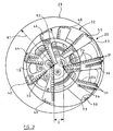
- Figure 4A shows an end view perspective of the drillout bi-center drill bit of Figure 1 illustrating the iris shaped third region;
- Figure 4B shows a simplified end view of the iris shaped third region of a drillout bi-center drill bit similar to that of Figure 4A;
- Figures 5-7 show perspective views of various cutting elements that are mounted in the iris shaped third region on the drillout bi-center drill bit in accordance with the present invention;
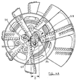
- Figure 8 is a partial end view of the face of the drillout bi-center drill bit showing an alternate cutter arrangement in accordance with another embodiment of the present invention;
- Figure 9 shows a perspective view of a cutting element of the embodiment of the drillout bi-center drill bit of Figure 8;
- Figure 10 shows a perspective view of still another cutter arrangement in accordance with another embodiment of the present invention.
-
- While the invention is susceptible to various modifications and alternative forms, specific embodiments thereof have been shown by way of example in the drawings and are herein described in detail. It should be understood, however, that the description herein of specific embodiments is not intended to limit the invention to the particular forms disclosed, but on the contrary, the intention is to cover all modifications, equivalents, and alternatives falling within the spirit and scope of the invention as defined by the appended claims.
- Illustrative embodiments of the invention are described below. In the interest of clarity, not all features of an actual implementation are described in this specification. It will of course be appreciated that in the development of any such actual embodiment, numerous implementation-specific decisions must be made to achieve the developers' specific goals, such as compliance with system-related and business-related constraints, which will vary from one implementation to another. Moreover, it will be appreciated that such a development effort might be complex and time-consuming, but would nevertheless be a routine undertaking for those of ordinary skill in the art having the benefit of this disclosure.
- Turning now to the drawings, and specifically referring to Figures 1, 2A, 2B, and 2C, a drillout
bi-center drill bit 10 having multi-directional cutters is shown in accordance with one embodiment of the present invention. The drilloutbi-center drill bit 10 has alongitudinal axis 11 upon which thedrill bit 10 rotates, and abit body 12 with afirst end 14 adapted to be secured to a drill string (not shown) for driving thedrill bit 10. According to one embodiment,threads 16 may be used for coupling thedrill bit 10 to the drill string. However, it will be appreciated to those of ordinary skill in the art that various other forms of attachment may be used in lieu of the threads without departing from the spirit and scope of the present invention. At a second, opposite end of thebit body 12 is apilot section 18 of the drillout bi-centerdrill bit 10. A reamer section, shown generally bynumeral 20, is intermediate thefirst end 14 and thepilot section 18 of thebi-center drill bit 10. - While in operation, the
bit body 12 is rotated via the drill string by some external means while the drilloutbi-center drill bit 10 is forced into the material being drilled. The rotation under load causescutting elements 24 at the exposed at thecutting face 17 to penetrate into the drilled material and remove the material in a scraping and/or gouging fashion. - In accordance with one embodiment of the present invention, the
bit body 12 includes internal passaging (not shown) that allows pressurized drilling fluid to be supplied from the drilling surface to a plurality ofnozzle orifices 22. Thesenozzle orifices 22 discharge the drilling fluid to clean and cool thecutting elements 24 as they engage the material being drilled. The drilling fluid also functions to transport the drilled material to the surface for disposal. - According to one embodiment, the
pilot section 18 may have a section with at least onefluid passage 26 provided for return flow of the drilling fluid. There also may be otherfluid passages 26 provided in thereamer section 20 of the drilloutbi-center drill bit 10 as well. - Referring specifically to Figures 2B and 2C, side view perspectives of the drillout
bi-center drill bit 10 of the present invention are shown. One important characteristic of the drilloutbi-center drill bit 10 is its ability to drill a borehole 11 into the earth 13 with a gauge drilling diameter larger than the inside diameter of thecasing 15, or pipe or other type of conductor thebit 10 passes through, which is shown in Figure 2C. - Another important characteristic of the of the drillout
bi-center drill bit 10 is its ability to drill out cement 17 (and related hardware, not shown) inside thecasing 15 as shown in Figure 2B without causing damage to thecasing 15 or the cuttingelements 24 of thedrill bit 10. - Turning now to Figure 3, an end view of a drillout
bi-center drill bit 10 of the present invention is shown. The gauge drilling diameter, as indicated by thecircle 28, is generated by radius R1 from a first center ofrotation 30 of thepilot section 18. In this drilling mode, the circular portion of thepilot section 18 will be concentric with thediameter 28. The cuttingelements 24 on the portion of thereamer section 20 radially furthest from the first center ofrotation 30 actually drill the gauge drilling diameter of theborehole 11, as indicated atnumeral 31. Thereamer section 20 is formed eccentrically of thepilot section 18, so only a portion of the wall of theborehole 11 is in contact with the cuttingelements 24, which cut the final gauge of the borehole 11 at any given time during operation. - The drillout
bi-center drill bit 10 also has a pass through diameter, as indicated by thecircle 32, generated by radius R2 from a second center ofrotation 34 of thepilot section 18. The shortest linear distance at the face of the bit between the centers ofrotation rotation 34 is on the centerline of the smallest cylinder that may be fitted about the drilloutbi-center drill bit 10. To be effective, the pass through diameter that is indicated bycircle 32 must be smaller than the inside diameter of thecasing 15 that the drilloutbi-center drill bit 10 must pass through. - For optimal life, the cutting
elements 24 must be oriented on thepilot section 18 in a known manner with respect to the direction of scraping through the material being drilled. This is no problem for bi-center drill bits that do not drill the cement and related hardware out of the casing. However, when a drillout bi-center drill bit is drilling the cement and related hardware in the casing, some of the cuttingelements 24 may be subjected to reverse scraping while rotating about the second center ofrotation 34. Reverse scraping often causes rapid degradation of the cuttingelements 24, and must be avoided. - The cutting
elements 24 are typically polycrystalline diamond compact cutters or PDC. A PDC is typically comprised of a facing table of diamond or other superhard substance bonded to a less hard substrate material, typically formed of but not limited to, tungsten carbide. The PDC is then often attached by a method known as long substrate bonding to a post or cylinder for insertion into thebit body 12. This PDC type of cuttingelement 24 is particularly sensitive to reverse scraping because loading from reverse scraping can easily destroy both the diamond table bonding and the long substrate bonding. - In prior art drill bits, the cutting elements are typically configured with a single cutting surface, where the cutting surface is properly oriented to cut through material being drilled when the drill bit rotates around a first center of rotation, such as center of
rotation 30, for example. However, when the drilloutbi-center drill bit 10 rotates around a second center of rotation, such as center ofrotation 34, for example, the cutting surface of the cutting element is not properly oriented to optimally cut through the drilled material. That is, when the cutting element is configured with this single cutting surface, the drill bit is optimally utilized while drilling around the first center of rotation, but is not optimally positioned to cut material when the drill bit rotates around a second center of rotation. With this particular prior art configuration, the cutting element will undesirably wear at a faster rate when the drill bit is rotating around the center of rotation where the single cutting surface of the cutting element is not optimally positioned to cut material. As a result of the cutting elements wearing at a faster rate, the life of the drill bit is undesirably shortened. - As previously stated, the distance D is the shortest linear distance between center of
rotation 30 and center ofrotation 34. As shown in Figure 4A, afirst region 56 of thepilot section 18, centered about the first center ofrotation 30, has a radius D. Asecond region 58 of thepilot section 18 centered about the second center ofrotation 34, and also has a radius D. Athird region 60 of thepilot section 18 is formed by the intersection of thefirst region 56 and thesecond region 58. This iris shapedthird region 60 is the critical area where reverse cutter scraping is possible. - Turning now to Figure 4B, a diagrammatic view of the positions of some of the cutting elements of a drillout bi-center drill bit similar to that of Figure 4A is shown. Three cutting
elements third region 60 between the drilling center ofrotation 30 and the passthrough center ofrotation 34. -
Cutter 72 has two cutting faces 78, 80. When the drilloutbi-center drill bit 10 is rotating about the drilling center ofrotation 30, cuttingface 80 ofcutter 72 is properly oriented for cutting along the path indicated byarrow 82. Cuttingface 80 is generally oriented perpendicular to the direction of travel of thecutter 72 in this operating mode which is parallel to dashedline 86 passing through about the drilling center ofrotation 30. - In a similar manner, when the drillout
bi-center drill bit 10 is rotating about the passthrough center ofrotation 34, cuttingface 78 ofcutter 72 is properly oriented for cutting along the path indicated byarrow 84. Cuttingface 78 is generally oriented perpendicular to the direction of travel of thecutter 72 in this operating mode which is parallel to dashedline 88 passing through about the passthrough center ofrotation 34 -
Cutter 72 may be formed of any material suitable for drilling earth formations. Since the wear rate of cutting elements near the center of the bit is generally low, cemented tungsten carbide may be suitable. It is understood that during drillout operation, only a small amount of wear is likely to occur on cuttingface 78 ofcutter 72. It would be expected that much more wear would occur onface 80 when the bit is drilling into the earth. If the wear rates are unacceptably high, thecutter 72 may be formed of an infiltrated material comprising metallic powders such as tungsten carbide mixed with diamond particles and a binder. -
Cutter 74 operates in a manner similar tocutter 72, although as described later,cutter 74 is intended for much more abrasive drilling thancutter 72.Cutter 74 has two cutting faces 90, 92. When the drilloutbi-center drill bit 10 is rotating about the drilling center ofrotation 30, cuttingface 90 ofcutter 74 is properly oriented for cutting along the path indicated byarrow 94. Cuttingface 90 is generally oriented perpendicular to the direction of travel of thecutter 74 in this operating mode which is parallel to dashedline 98 passing through about the drilling center ofrotation 30. - In a similar manner, when the drillout
bi-center drill bit 10 is rotating about the passthrough center ofrotation 34, cuttingface 92 ofcutter 74 is properly oriented for cutting along the path indicated byarrow 96. Cuttingface 92 is generally oriented perpendicular to the direction of travel of thecutter 74 in this operating mode which is parallel to dashedline 100 passing through about the passthrough center ofrotation 34. - In order to survive severe, abrasive drilling conditions the cutting
face 92 ofcutter 74 is quite different from that ofcutter 72. APDC cutting element 102 is mounted on cutting face 92 asmall distance 104 from theend 106 ofcutter 74 exposed at the cuttingface 17 of the drill outbi-center drill bit 10. During the drillout phase, a small amount of wear will occur onend 106. After drillout, the bit will then start drilling a full diameter hole in the earth. However, in abrasive drilling conditions, even cutters near the center will wear rapidly. Therefore, theend 106 ofcutter 74 will wear rapidly, exposing thePDC element 102. Once this happens, the cutter will wear at a rate comparable to other PDC cutters near the center. - In this embodiment, the PDC is attached to the
cutter 76 by a method known as long substrate bonding. Thecutter 76 is then inserted into thebit body 12, which gives the PDCs an alternative orientation with respect to the center of rotation about which thedrill bit 10 rotates. - It should be apparent that
cutters third region 60 between the drilling center ofrotation 30 and the passthrough center ofrotation 34. Although some mis-match of cutting faces 78, 80, 90, 92 would be tolerated, allowing some commonality of cutting face orientations, many different configurations ofcutters bi-center drill bits 10. - One alternate, a cone shaped
cutter 76 suitable for very non-abrasive drilling condition, is shown in Figure 7. Incutter 76, theside 108 is generally conic and terminates in a flat top 110 that is also exposed at the cuttingface 17. Since thesecutters 76 are symmetrical, they may be placed anywhere within the iris shapedthird region 60 between the drilling center ofrotation 30 and the passthrough center ofrotation 34. In thiscutter 76, thecutting edge 112 is the intersection of theside 108 and theflat top 110. Although not particularly 'sharp',cutter 76 is suitable for non-abrasive drilling conditions. - Shown in Figure 8 is a particular bit configuration where the cutting functions for drillout and full diameter drilling are embodied in separate cutters. Two cutting
face sections 17 are shown onbit body 12. A plurality ofconventional cutters 24 is shown witharrows 114 indicating their rotation path about the drilling center ofrotation 30. A plurality of cutters 116 (shown in Figure 9) have cutting faces 118 oriented for drilling out, witharrows 119 indicating their rotation path about the passthrough center ofrotation 34. - The
tops 120 ofcutters 116 are orientated relatively farther from thebit body 12 than the remainder ofcutters 24 on the cuttingface section 17 of the drillout bi-centerbit 10. Therefore the cutting faces 118 ofcutters 116 will engage the drillout material and prevent damage tocutters 24 during drillout. Once drillout is complete, thecutters 116 will rapidly wear, allowing thecutters 24 to drill normally. The operation is therefore effectively the same ascutter 74.Cutter 116 may be formed of any material suitable for drilling earth formations. However, similar tocutter 74, a cemented tungsten carbide material or an infiltrated material comprising metallic powders such as tungsten carbide mixed with diamond particles and a binder is suitable. In this embodiment and similar tocutters cutter 116 is oriented as necessary then fixed into thebit body 12, - An alternate embodiment for the arrangement of the drillout cutters shown in Figure 8 is possible when the
bit body 12 is an infiltrated powdered metal matrix material. When this is the case, thecutter 122 is formed as a bump in the matrix of thebit body 12. The cuttingface 118, and top 120, ofcutter 122 function identically tocutter 116. However, because matrix bits are made in a moulding process, orienting and fixing thecutters 122 into thebit body 12 is not necessary.Cutter 122 is integral with the bit body. This method of construction of matrix drill bits is well known in the art. Accordingly, the specific details of such will not be disclosed herein to avoid unnecessarily obscuring the present invention. - The particular embodiments disclosed above are illustrative only, as the invention may be modified and practiced in different but equivalent manners apparent to those skilled in the art having the benefit of the teachings herein. Furthermore, no limitations are intended to the details of construction or design herein shown, other than as described in the claims below. It is therefore evident that the particular embodiments disclosed above may be altered or modified and all such variations are considered within the scope and spirit of the invention.
Claims (9)
- A drill-out bi-centre drill bit comprising a bit body with a first end adapted to be detachably secured to a drill string, a pilot section on a second, opposite end of the bit body and a reamer section intermediate the first and second ends, the pilot section having a first drilling centre of rotation and a second passthrough centre of rotation spaced apart from the first centre of rotation by a non-zero distance D, the pilot section further having a first region centred about the first centre of rotation and having a radius D, a second region centred about the second centre of rotation and having a radius D, and a third region formed by the intersection of the first region and the second region, a cutting element being fixed on the bit body within the third region, the cutting element having a first cutting face generally oriented perpendicular to the direction of travel of the cutting element about first centre of rotation of the pilot section and a second cutting face generally oriented perpendicular to the direction of travel of the cutting element about the second centre of rotation.
- A bit according to Claim 1, wherein the cutting element is of cemented tungsten carbide form.
- A bit according to Claim 1, wherein the cutting element is formed of an infiltrated material comprising metallic powders mixed with diamond particles and a binder.
- A bit according to Claim 1, wherein a polycrystalline diamond compact cutter is mounted on one of the cutting faces of the cutting element.
- A bit according to Claim 1, wherein the cutting element is of generally conical form, the first and second cutting faces being defined by different parts of a generally conical surface of the cutting element.
- A drill-out bi-centre drill bit comprising a bit body with a longitudinal axis and a first end adapted to be detachably secured to a drill string, a pilot section on a second, opposite end of the bit body and a reamer section intermediate the first and second ends, the pilot section having a first drilling centre of rotation and a second passthrough centre of rotation spaced apart from the first centre of rotation by a non-zero distance D, the pilot section further having a first region centred about the first centre of rotation having a radius D, a second region centred about the second centre of rotation having a radius D, and a third region formed by the intersection of the first region and the second region, a plurality of first cutters being positioned in the third region, with superhard cutting faces generally oriented perpendicular to the direction of travel of the cutting element about the first centre of rotation, projecting a distance from the bit body, and at least one second cutter on the bit body within the third region and projecting a distance from the bit body greater than the projection of the first cutters, with a cutting face orientated generally perpendicular to the direction of travel of the second cutter about the second centre of rotation.
- A bit as claimed in Claim 6, wherein the or each second cutter is of cemented tungsten carbide form.
- A bit as claimed in Claim 6, wherein the or each second cutter is of an infiltrated material comprising a mixture of metallic powders, diamond particles and a binder.
- A bit as claimed in Claim 6, wherein the bit body is of infiltrated powdered metal matrix form and is shaped to define the or each second cutter.
Applications Claiming Priority (2)
| Application Number | Priority Date | Filing Date | Title |
|---|---|---|---|
| US22704900P | 2000-08-21 | 2000-08-21 | |
| US227049P | 2000-08-21 |
Publications (2)
| Publication Number | Publication Date |
|---|---|
| EP1182323A1 true EP1182323A1 (en) | 2002-02-27 |
| EP1182323B1 EP1182323B1 (en) | 2003-09-10 |
Family
ID=22851532
Family Applications (1)
| Application Number | Title | Priority Date | Filing Date |
|---|---|---|---|
| EP20010305833 Expired - Lifetime EP1182323B1 (en) | 2000-08-21 | 2001-07-05 | Multi-directional cutters for bi-center drillout bits |
Country Status (4)
| Country | Link |
|---|---|
| US (1) | US20020020565A1 (en) |
| EP (1) | EP1182323B1 (en) |
| DE (1) | DE60100727T2 (en) |
| ZA (1) | ZA200105680B (en) |
Cited By (1)
| Publication number | Priority date | Publication date | Assignee | Title |
|---|---|---|---|---|
| CN117514016A (en) * | 2024-01-03 | 2024-02-06 | 西南石油大学 | PDC drill bit with reversely-mounted teeth |
Families Citing this family (33)
| Publication number | Priority date | Publication date | Assignee | Title |
|---|---|---|---|---|
| US7395882B2 (en) | 2004-02-19 | 2008-07-08 | Baker Hughes Incorporated | Casing and liner drilling bits |
| US7954570B2 (en) | 2004-02-19 | 2011-06-07 | Baker Hughes Incorporated | Cutting elements configured for casing component drillout and earth boring drill bits including same |
| US20070261890A1 (en) * | 2006-05-10 | 2007-11-15 | Smith International, Inc. | Fixed Cutter Bit With Centrally Positioned Backup Cutter Elements |
| GB2453875C (en) | 2006-10-02 | 2009-09-16 | Smith International | Drill bits with dropping tendencies |
| US7703557B2 (en) * | 2007-06-11 | 2010-04-27 | Smith International, Inc. | Fixed cutter bit with backup cutter elements on primary blades |
| US8915166B2 (en) * | 2007-07-27 | 2014-12-23 | Varel International Ind., L.P. | Single mold milling process |
| US8720604B2 (en) * | 2007-08-15 | 2014-05-13 | Schlumberger Technology Corporation | Method and system for steering a directional drilling system |
| US20100038141A1 (en) * | 2007-08-15 | 2010-02-18 | Schlumberger Technology Corporation | Compliantly coupled gauge pad system with movable gauge pads |
| US8066085B2 (en) * | 2007-08-15 | 2011-11-29 | Schlumberger Technology Corporation | Stochastic bit noise control |
| US8757294B2 (en) * | 2007-08-15 | 2014-06-24 | Schlumberger Technology Corporation | System and method for controlling a drilling system for drilling a borehole in an earth formation |
| US8899352B2 (en) | 2007-08-15 | 2014-12-02 | Schlumberger Technology Corporation | System and method for drilling |
| US8534380B2 (en) | 2007-08-15 | 2013-09-17 | Schlumberger Technology Corporation | System and method for directional drilling a borehole with a rotary drilling system |
| US8763726B2 (en) * | 2007-08-15 | 2014-07-01 | Schlumberger Technology Corporation | Drill bit gauge pad control |
| US7954571B2 (en) | 2007-10-02 | 2011-06-07 | Baker Hughes Incorporated | Cutting structures for casing component drillout and earth-boring drill bits including same |
| US8245797B2 (en) * | 2007-10-02 | 2012-08-21 | Baker Hughes Incorporated | Cutting structures for casing component drillout and earth-boring drill bits including same |
| GB2454918B (en) * | 2007-11-23 | 2011-11-02 | Schlumberger Holdings | Adjustable drill bit |
| US9016407B2 (en) | 2007-12-07 | 2015-04-28 | Smith International, Inc. | Drill bit cutting structure and methods to maximize depth-of-cut for weight on bit applied |
| US7938204B2 (en) * | 2007-12-21 | 2011-05-10 | Baker Hughes Incorporated | Reamer with improved hydraulics for use in a wellbore |
| SA108290832B1 (en) | 2007-12-21 | 2012-06-05 | بيكر هوغيس انكوربوريتد | Reamer with Stabilizer Arms for Use in A Wellbore |
| SA108290829B1 (en) * | 2007-12-21 | 2012-01-24 | بيكر هوغيس انكوربوريتد | Reamer with Balanced Cutting Structure for Use in A Wellbore |
| WO2009146078A1 (en) | 2008-04-01 | 2009-12-03 | Smith International, Inc. | Fixed cutter bit with backup cutter elements on secondary blades |
| US7849940B2 (en) * | 2008-06-27 | 2010-12-14 | Omni Ip Ltd. | Drill bit having the ability to drill vertically and laterally |
| US8327951B2 (en) * | 2008-06-27 | 2012-12-11 | Omni Ip Ltd. | Drill bit having functional articulation to drill boreholes in earth formations in all directions |
| US8746368B2 (en) * | 2008-08-13 | 2014-06-10 | Schlumberger Technology Corporation | Compliantly coupled gauge pad system |
| WO2010115146A2 (en) * | 2009-04-02 | 2010-10-07 | Jones Mark L | Drill bit for earth boring |
| US20110005841A1 (en) * | 2009-07-07 | 2011-01-13 | Baker Hughes Incorporated | Backup cutting elements on non-concentric reaming tools |
| US20110100714A1 (en) * | 2009-10-29 | 2011-05-05 | Moss William A | Backup cutting elements on non-concentric earth-boring tools and related methods |
| CN102251746B (en) * | 2011-06-30 | 2013-11-06 | 中国神华能源股份有限公司 | Drill bit and sampling device |
| PL3135854T3 (en) * | 2015-08-24 | 2022-06-20 | Politechnika Gdańska | Wellbore reaming tool |
| CN105401885A (en) * | 2015-11-09 | 2016-03-16 | 重庆大学 | Drill bit suitable for large-diameter drilling of coal or soft rock |
| GB201907970D0 (en) * | 2019-06-04 | 2019-07-17 | Element Six Uk Ltd | A cutting element and method of making same |
| WO2022015733A1 (en) | 2020-07-15 | 2022-01-20 | Shear Bits, Inc. | Wellbore reaming tool having fixed mounted gouging cutters |
| US11821263B2 (en) * | 2020-10-16 | 2023-11-21 | Saudi Arabian Oil Company | Reversible polycrystalline diamond compact bit |
Citations (16)
| Publication number | Priority date | Publication date | Assignee | Title |
|---|---|---|---|---|
| US1587266A (en) | 1922-11-14 | 1926-06-01 | John A Zublin | Means for forming a well bore |
| US1758773A (en) | 1926-03-20 | 1930-05-13 | Universal Engineering Company | Method of and bit for cutting alpha hole larger than the bit |
| US2074951A (en) | 1935-12-14 | 1937-03-23 | John A Zublin | Bit for drilling a hole larger than the bit |
| US2953354A (en) | 1958-05-15 | 1960-09-20 | Edward B Williams Iii | Drill bit |
| US3367430A (en) | 1966-08-24 | 1968-02-06 | Christensen Diamond Prod Co | Combination drill and reamer bit |
| GB2086451A (en) * | 1980-10-21 | 1982-05-12 | Christensen Inc | Rotary drill bit for deep-well drilling |
| US4408669A (en) | 1977-04-29 | 1983-10-11 | Sandvik Aktiebolag | Means for drilling |
| US4440246A (en) * | 1981-04-11 | 1984-04-03 | Christensen, Inc. | Cutting member for rotary drill bits |
| US4440244A (en) | 1980-03-26 | 1984-04-03 | Santrade Ltd. | Drill tool |
| US4635738A (en) | 1984-04-14 | 1987-01-13 | Norton Christensen, Inc. | Drill bit |
| US4932484A (en) * | 1989-04-10 | 1990-06-12 | Amoco Corporation | Whirl resistant bit |
| US5040621A (en) | 1989-04-05 | 1991-08-20 | Uniroc Aktiebolag | Flushing means for drilling tools |
| US5279375A (en) * | 1992-03-04 | 1994-01-18 | Baker Hughes Incorporated | Multidirectional drill bit cutter |
| EP0874128A2 (en) * | 1997-04-26 | 1998-10-28 | Camco International (UK) Limited | Rotary drill bit having movable formation-engaging members |
| EP1091083A1 (en) * | 1999-08-09 | 2001-04-11 | Diamond Products International, Inc. | Bi-center bit adapted to drill casing shoe |
| EP1096103A1 (en) * | 1999-10-28 | 2001-05-02 | Schlumberger Holdings Limited | Drill-out bi-center bit |
-
2001
- 2001-07-05 DE DE60100727T patent/DE60100727T2/en not_active Expired - Lifetime
- 2001-07-05 EP EP20010305833 patent/EP1182323B1/en not_active Expired - Lifetime
- 2001-07-11 ZA ZA200105680A patent/ZA200105680B/en unknown
- 2001-08-03 US US09/682,193 patent/US20020020565A1/en not_active Abandoned
Patent Citations (16)
| Publication number | Priority date | Publication date | Assignee | Title |
|---|---|---|---|---|
| US1587266A (en) | 1922-11-14 | 1926-06-01 | John A Zublin | Means for forming a well bore |
| US1758773A (en) | 1926-03-20 | 1930-05-13 | Universal Engineering Company | Method of and bit for cutting alpha hole larger than the bit |
| US2074951A (en) | 1935-12-14 | 1937-03-23 | John A Zublin | Bit for drilling a hole larger than the bit |
| US2953354A (en) | 1958-05-15 | 1960-09-20 | Edward B Williams Iii | Drill bit |
| US3367430A (en) | 1966-08-24 | 1968-02-06 | Christensen Diamond Prod Co | Combination drill and reamer bit |
| US4408669A (en) | 1977-04-29 | 1983-10-11 | Sandvik Aktiebolag | Means for drilling |
| US4440244A (en) | 1980-03-26 | 1984-04-03 | Santrade Ltd. | Drill tool |
| GB2086451A (en) * | 1980-10-21 | 1982-05-12 | Christensen Inc | Rotary drill bit for deep-well drilling |
| US4440246A (en) * | 1981-04-11 | 1984-04-03 | Christensen, Inc. | Cutting member for rotary drill bits |
| US4635738A (en) | 1984-04-14 | 1987-01-13 | Norton Christensen, Inc. | Drill bit |
| US5040621A (en) | 1989-04-05 | 1991-08-20 | Uniroc Aktiebolag | Flushing means for drilling tools |
| US4932484A (en) * | 1989-04-10 | 1990-06-12 | Amoco Corporation | Whirl resistant bit |
| US5279375A (en) * | 1992-03-04 | 1994-01-18 | Baker Hughes Incorporated | Multidirectional drill bit cutter |
| EP0874128A2 (en) * | 1997-04-26 | 1998-10-28 | Camco International (UK) Limited | Rotary drill bit having movable formation-engaging members |
| EP1091083A1 (en) * | 1999-08-09 | 2001-04-11 | Diamond Products International, Inc. | Bi-center bit adapted to drill casing shoe |
| EP1096103A1 (en) * | 1999-10-28 | 2001-05-02 | Schlumberger Holdings Limited | Drill-out bi-center bit |
Cited By (1)
| Publication number | Priority date | Publication date | Assignee | Title |
|---|---|---|---|---|
| CN117514016A (en) * | 2024-01-03 | 2024-02-06 | 西南石油大学 | PDC drill bit with reversely-mounted teeth |
Also Published As
| Publication number | Publication date |
|---|---|
| US20020020565A1 (en) | 2002-02-21 |
| ZA200105680B (en) | 2002-02-06 |
| EP1182323B1 (en) | 2003-09-10 |
| DE60100727T2 (en) | 2004-07-22 |
| DE60100727D1 (en) | 2003-10-16 |
Similar Documents
| Publication | Publication Date | Title |
|---|---|---|
| EP1182323B1 (en) | Multi-directional cutters for bi-center drillout bits | |
| US6606923B2 (en) | Design method for drillout bi-center bits | |
| AU2020201994B2 (en) | Rotational drill bits and drilling apparatuses including the same | |
| US11255129B2 (en) | Shaped cutters | |
| US6527065B1 (en) | Superabrasive cutting elements for rotary drag bits configured for scooping a formation | |
| CN107075920B (en) | Earth-boring tool and cutting element for same | |
| US8833492B2 (en) | Cutters for fixed cutter bits | |
| US4352400A (en) | Drill bit | |
| US11035177B2 (en) | Shaped cutters | |
| US10100582B2 (en) | Rotational drill bits and drilling apparatuses including the same | |
| US20100300673A1 (en) | Side track bit | |
| US2966949A (en) | Full hole permanent drill bit | |
| EP1236861A1 (en) | Mill/drill bit | |
| EA027355B1 (en) | Kerfing hybrid drill bit | |
| US9951564B1 (en) | Rotational drill bits and drilling apparatuses including the same | |
| US20110100714A1 (en) | Backup cutting elements on non-concentric earth-boring tools and related methods | |
| US20150233186A1 (en) | Drill bit | |
| EP0145422A2 (en) | Improvements in rotary drill bits | |
| US4632196A (en) | Drill bit with shrouded cutter | |
| US20200362640A1 (en) | Drill bit with cutting gauge pad | |
| EP1270868B1 (en) | A bi-centre bit for drilling out through a casing shoe | |
| GB2301386A (en) | Drill bit | |
| US20180202232A1 (en) | Drill bit having shear cutters with reduced diameter substrate |
Legal Events
| Date | Code | Title | Description |
|---|---|---|---|
| PUAI | Public reference made under article 153(3) epc to a published international application that has entered the european phase |
Free format text: ORIGINAL CODE: 0009012 |
|
| AK | Designated contracting states |
Kind code of ref document: A1 Designated state(s): AT BE CH CY DE DK ES FI FR GB GR IE IT LI LU MC NL PT SE TR Kind code of ref document: A1 Designated state(s): BE DE FR GB IE |
|
| AX | Request for extension of the european patent |
Free format text: AL;LT;LV;MK;RO;SI |
|
| 17P | Request for examination filed |
Effective date: 20020114 |
|
| 17Q | First examination report despatched |
Effective date: 20020408 |
|
| GRAH | Despatch of communication of intention to grant a patent |
Free format text: ORIGINAL CODE: EPIDOS IGRA |
|
| RAP1 | Party data changed (applicant data changed or rights of an application transferred) |
Owner name: CAMCO INTERNATIONAL (UK) LIMITED |
|
| AKX | Designation fees paid |
Free format text: BE DE FR GB IE |
|
| GRAH | Despatch of communication of intention to grant a patent |
Free format text: ORIGINAL CODE: EPIDOS IGRA |
|
| GRAA | (expected) grant |
Free format text: ORIGINAL CODE: 0009210 |
|
| AK | Designated contracting states |
Kind code of ref document: B1 Designated state(s): BE DE FR GB IE |
|
| REG | Reference to a national code |
Ref country code: GB Ref legal event code: FG4D |
|
| REF | Corresponds to: |
Ref document number: 60100727 Country of ref document: DE Date of ref document: 20031016 Kind code of ref document: P |
|
| REG | Reference to a national code |
Ref country code: IE Ref legal event code: FG4D |
|
| ET | Fr: translation filed | ||
| PLBE | No opposition filed within time limit |
Free format text: ORIGINAL CODE: 0009261 |
|
| STAA | Information on the status of an ep patent application or granted ep patent |
Free format text: STATUS: NO OPPOSITION FILED WITHIN TIME LIMIT |
|
| 26N | No opposition filed |
Effective date: 20040614 |
|
| PGFP | Annual fee paid to national office [announced via postgrant information from national office to epo] |
Ref country code: IE Payment date: 20060712 Year of fee payment: 6 |
|
| PGFP | Annual fee paid to national office [announced via postgrant information from national office to epo] |
Ref country code: BE Payment date: 20060912 Year of fee payment: 6 |
|
| BERE | Be: lapsed |
Owner name: *CAMCO INTERNATIONAL UK LTD Effective date: 20070731 |
|
| REG | Reference to a national code |
Ref country code: IE Ref legal event code: MM4A |
|
| PG25 | Lapsed in a contracting state [announced via postgrant information from national office to epo] |
Ref country code: BE Free format text: LAPSE BECAUSE OF NON-PAYMENT OF DUE FEES Effective date: 20070731 |
|
| PG25 | Lapsed in a contracting state [announced via postgrant information from national office to epo] |
Ref country code: IE Free format text: LAPSE BECAUSE OF NON-PAYMENT OF DUE FEES Effective date: 20070705 |
|
| REG | Reference to a national code |
Ref country code: FR Ref legal event code: PLFP Year of fee payment: 16 |
|
| REG | Reference to a national code |
Ref country code: FR Ref legal event code: PLFP Year of fee payment: 17 |
|
| REG | Reference to a national code |
Ref country code: FR Ref legal event code: PLFP Year of fee payment: 18 |
|
| PGFP | Annual fee paid to national office [announced via postgrant information from national office to epo] |
Ref country code: FR Payment date: 20200612 Year of fee payment: 20 |
|
| PGFP | Annual fee paid to national office [announced via postgrant information from national office to epo] |
Ref country code: GB Payment date: 20200624 Year of fee payment: 20 |
|
| PGFP | Annual fee paid to national office [announced via postgrant information from national office to epo] |
Ref country code: DE Payment date: 20200624 Year of fee payment: 20 |
|
| REG | Reference to a national code |
Ref country code: DE Ref legal event code: R071 Ref document number: 60100727 Country of ref document: DE |
|
| REG | Reference to a national code |
Ref country code: GB Ref legal event code: PE20 Expiry date: 20210704 |
|
| PG25 | Lapsed in a contracting state [announced via postgrant information from national office to epo] |
Ref country code: GB Free format text: LAPSE BECAUSE OF EXPIRATION OF PROTECTION Effective date: 20210704 |