EP1182291A2 - Front loader washing machine with a tub with balancing weights - Google Patents
Front loader washing machine with a tub with balancing weights Download PDFInfo
- Publication number
- EP1182291A2 EP1182291A2 EP01117768A EP01117768A EP1182291A2 EP 1182291 A2 EP1182291 A2 EP 1182291A2 EP 01117768 A EP01117768 A EP 01117768A EP 01117768 A EP01117768 A EP 01117768A EP 1182291 A2 EP1182291 A2 EP 1182291A2
- Authority
- EP
- European Patent Office
- Prior art keywords
- tub
- balancing weights
- washing machine
- loader washing
- machine according
- Prior art date
- Legal status (The legal status is an assumption and is not a legal conclusion. Google has not performed a legal analysis and makes no representation as to the accuracy of the status listed.)
- Granted
Links
Images


Classifications
-
- D—TEXTILES; PAPER
- D06—TREATMENT OF TEXTILES OR THE LIKE; LAUNDERING; FLEXIBLE MATERIALS NOT OTHERWISE PROVIDED FOR
- D06F—LAUNDERING, DRYING, IRONING, PRESSING OR FOLDING TEXTILE ARTICLES
- D06F37/00—Details specific to washing machines covered by groups D06F21/00 - D06F25/00
- D06F37/26—Casings; Tubs
- D06F37/265—Counterweights mounted to the tub; Mountings therefor
Definitions
- the invention concerns a front-loading washing machine with a drum that is rotatably mounted in a tub, whereby the tub is provided with balancing weights at the laundry opening.
- a front-loader washing machine with a tub connected to balancing weights is prior art in DE OS 26 33 603.
- the open face of the tub is provided with an angled edge to which a bearing ring is affixed by means of a tightening band and sealing ring.
- the balancing weights are screwed to the bearing ring so that their outer contours do not project beyond the other contour of the tub. Given this means of fastening the balancing weights, the diameter of the laundry opening and the size of the door are limited, and it is difficult to affix the balancing weights.
- the problem of the invention is to design a front-loading washing machine of the initially-cited kind so that the balancing weights can be definitely affixed to the tub and leave the face free so that this area for the larger laundry opening can be sealed with a large door.
- circular-arc-shaped balancing weights have an essentially T-shaped cross-section, and a transverse leg lies on the outside of the front of the tub, and molded-on segments that project from the transverse leg are inserted and held in a form-fit receiving groove open to the front and created in the front of the tub.
- the balancing weights By designing the balancing weights in an essentially T-shape, moving them to the outside of the front of the tub, and placing a part of the balancing weights in the receiving groove that is recessed in relationship to the laundry opening allows the laundry opening to be large and makes it easy to attach a large door since it is not hindered by the balancing weights. This is an important feature for front-loading washing machines with a drum rotary axis that angles from front and back.
- two identical balancing weights are affixed diametrically opposed to the front of the tub, the balancing weights extend over less than 180° of the perimeter of the front, projecting mounting flanges are affixed to both ends and the middle of the balancing weights, and the balancing weights are made of concrete into which the mounting flanges are cast.
- the balancing weights can be affixed to the tub in a manner such that the receiving groove in the front of the tub forms a transitional wall to the drum bearing to which are attached (preferably molded on) radial sections of C-shaped mounting bars, and nuts for screw connections are placed in the mounting bar sections that can be used to screw the mounting flanges of the balancing weights to the mounting bars.
- the six mounting bar sections can be distributed at 60° intervals so that the mounting flanges of the balancing weights in the same section permit the balancing weights to be arranged in a diametrically opposed manner.
- the mounting flanges of the balancing weights must be in the same plane, and the middle mounting flanges project on the concave sides of the transverse legs of the circular-arc-shaped balancing weights so that the balancing weights can be correctly positioned.
- the method of the fixing the balancing weights to the front of the tub can be improved in that the end section of the front of the tub forms a receiving groove open to the outside in which the segments projecting on the concave inside of the balancing weights are inserted in a form-fit and held.
- the thickness of the transverse legs can be reduced with the provided weight.
- the face of the end section of the front of the tub remains free and can be used for affixing the door and the opening collar.
- the end section of the front of the tub and the balancing weights are harmonised with each other so that the outer contour of the balancing weights connected to the end section of the front of the tub does not project beyond the outer contour of the tub and unnecessarily restrict the oscillation of the tub in relation to the machine housing.
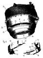
- Fig. 1 shows an exemplary embodiment of the tub 20 that has a separate front 10. At least the front 10 is designed and manufactured as a plastic injection-molded part. At the laundry opening 15, the front 10 transitions into an end section 13 with a smaller diameter. The transition 12 is perpendicular to the mid-axis of the tub 20. At the free face of the end section 13, a large door and an opening collar 30 can be affixed without being restricted as shown in the partial cross-section in Fig. 2.
- radial mounting bar sections 11 Molded as a single piece onto the transitional wall 12 of the front 10 that forms a part of the created receiving groove 14 are radial mounting bar sections 11 that have a T-shaped recess for nuts open to the loading side.
- the mounting bar sections 11 can be distributed at e.g. 60° intervals when the balancing weights 40 have three mounting flanges 41, 42 and 43 that are affixed (e.g. cast) in a projecting manner to the balancing weights 40 with the same distribution.
- the mounting flanges 41 and 42 project on the ends of the circular-arc-shaped balancing weights 40.
- the middle mounting flange 43 on the concave side is radially aligned on the balancing weight 40 to maintain the 60° distribution.
- All mounting flanges 41, 42 and 43 are in the same plane so that the two identical balancing weights 40 can be in the correct position diametrically opposed to each other screwed to the mounting bar sections 11 of the transitional wall 12.
- screw connections 50 are used that consist of a fixing screw that fits in a hole in the mounting flanges 41, 42, and 43, and a nut inserted in the mounting bar sections 11.
- the balancing weights 40 are made of concrete with cast mounting flanges 41, 42 and 43. Their weight is sufficient, and they are easy and economical to manufacture.
- the tub 20 with the drum in the machine housing and the pivot bearing and drive for the drum in the tub 20 can be attached in a conventional matter since this does not impair fastening the balancing weights 40 to the front 10 of the tub 20.
- the section in Fig. 3 shows a cross-section of the circular-arc-shaped balancing weights 40.
- the transverse legs 45 lie on the outside of the front 10 and are inserted in a form-fit together with the inwardly-projecting segments 44 into the receiving groove 14 of the end section 13 of the front 10.
- the transverse legs 45 of the balancing weights 40 do not project beyond the outer contour of the tub 20, and their distance from the machine housing is sufficient for the arising oscillations.
- the segments 44 in the receiving groove 14 allow the thickness of the transverse legs 45 to be small with the balancing weights 40 at the provided weight.
- the unit consisting of the tub 20 and drum do not take up more room in the machine housing, yet there is more room to attach the door and opening collar 30.
- the door can be larger which is advantageous when installing the drum and tub with a mid-axis that drops from the front and back that is hence the rotary axis of the drum.
Landscapes
- Engineering & Computer Science (AREA)
- Textile Engineering (AREA)
- Main Body Construction Of Washing Machines And Laundry Dryers (AREA)
- Component Parts Of Construction Machinery (AREA)
Abstract
Description
- Fig. 1
- a perspective front view of a tub with an affixed opening collar and two identical balancing weights in their mounted position,
- Fig. 2
- a partial cross-section of the front of the tub with diametrically opposed balancing weights on the end section, and
- Fig. 3
- another partial cross-section of the front of the tub that shows the T-shaped balancing weights in their affixed position.
Claims (8)
- A front-loader washing machine with a drum that is rotatably mounted in a tub, whereby balancing weights are provided at the laundry opening on the tub,
characterised in that
circular-arc-shaped balancing weights (40) have an essentially T-shaped cross-section, and their transverse leg (45) lies on the outside of the front (10) of the tub (20), and molded-on segments (44) that project from the transverse leg (45) are inserted and held in a form-fit receiving groove (15) open to the front that is created in the front (10) of the tub (20). - A front-loader washing machine according to claim 1,
characterised in that
two identical balancing weights (40) are affixed diametrically opposed to the front (10) of the tub;
the balancing weights (40) extend over less than 180° of the perimeter of the front (10), and
projecting mounting flanges (41,42,43) are affixed to both ends and the middle of the balancing weights (40). - A front-loader washing machine according to claims 1 or 2,
characterised in that
the balancing weights (40) are made of concrete into which the mounting flanges (41,42,43) are cast. - A front-loader washing machine according to one of claims 1 - 3,
characterised in that
the receiving groove (15) in the front (10) of the tub (20) forms a transitional wall (12) to the drum bearing to which are attached (preferably molded on) radial sections of C-shaped mounting bars (11), and
nuts for screw connections (50) are placed in the mounting bar sections (11) that can be used to screw the mounting flanges (41,42,43) of the balancing weights (40) to the mounting bars (11). - A front-loader washing machine according to claim 4,
characterised in that
the mounting flanges (41,42,43) of the balancing weights (40) are in the same plane. - A front-loader washing machine according to one of claims 1 - 5,
characterised in that
at least the front (10) of the tub (20) is designed as a plastic injection-molded part. - A front-loader washing machine according to one of claims 1 - 6,
characterised in that
the end section (13) of the front (10) of the tub (20) is connected to an opening collar (30). - A front-loader washing machine according to one of claims 1 - 7,
characterised in that
the transverse legs (45) of the balancing weights (40) connected to the end section (13) of the front (10) of the tub (20) do not project beyond the outer contour of the tub.
Applications Claiming Priority (2)
| Application Number | Priority Date | Filing Date | Title |
|---|---|---|---|
| DE10040400 | 2000-08-18 | ||
| DE10040400A DE10040400C1 (en) | 2000-08-18 | 2000-08-18 | Front loader washing machine has balance weights of T-shaped cross-section with arm in contact with washing solution container front surface, bridges engaging groove in front surface |
Publications (3)
| Publication Number | Publication Date |
|---|---|
| EP1182291A2 true EP1182291A2 (en) | 2002-02-27 |
| EP1182291A3 EP1182291A3 (en) | 2003-08-27 |
| EP1182291B1 EP1182291B1 (en) | 2005-11-16 |
Family
ID=7652870
Family Applications (1)
| Application Number | Title | Priority Date | Filing Date |
|---|---|---|---|
| EP01117768A Expired - Lifetime EP1182291B1 (en) | 2000-08-18 | 2001-08-01 | Front loader washing machine with a tub with balancing weights |
Country Status (3)
| Country | Link |
|---|---|
| EP (1) | EP1182291B1 (en) |
| DE (2) | DE10040400C1 (en) |
| ES (1) | ES2249365T3 (en) |
Cited By (5)
| Publication number | Priority date | Publication date | Assignee | Title |
|---|---|---|---|---|
| KR20050093254A (en) * | 2004-03-18 | 2005-09-23 | 주식회사 대우일렉트로닉스 | Assembly structure of reservoir for a washing machine |
| US8047025B2 (en) | 2006-04-12 | 2011-11-01 | Bsh Bosch Und Siemens Hausgeraete Gmbh | Tub for washing machine |
| CN103031696A (en) * | 2011-10-06 | 2013-04-10 | 三星电子株式会社 | Washing machine having balancer |
| CN111850978A (en) * | 2020-06-11 | 2020-10-30 | 青岛海尔滚筒洗衣机有限公司 | Outer tub of a washing machine and washing machine |
| CN113699734A (en) * | 2021-10-11 | 2021-11-26 | 珠海格力电器股份有限公司 | Drum washing machine without outer drum |
Families Citing this family (4)
| Publication number | Priority date | Publication date | Assignee | Title |
|---|---|---|---|---|
| DE10312723A1 (en) * | 2003-03-21 | 2004-09-30 | BSH Bosch und Siemens Hausgeräte GmbH | Method for producing a tub for a washing machine and tub made thereafter |
| CN102212952B (en) * | 2011-06-08 | 2016-11-23 | 青岛海尔滚筒洗衣机有限公司 | A kind of damping device of roller washing machine |
| ES2470496B1 (en) * | 2012-12-20 | 2015-03-31 | Bsh Electrodomésticos España, S.A. | Domestic appliance with a reservoir |
| CN113699736A (en) * | 2021-10-11 | 2021-11-26 | 珠海格力电器股份有限公司 | Drum washing machine without outer drum |
Family Cites Families (6)
| Publication number | Priority date | Publication date | Assignee | Title |
|---|---|---|---|---|
| DE2633603C2 (en) * | 1976-07-27 | 1981-11-19 | Licentia Patent-Verwaltungs-Gmbh, 6000 Frankfurt | Front loadable drum washing machine |
| DE3740206A1 (en) * | 1987-11-27 | 1989-06-08 | Bauknecht Hausgeraete | BALANCING WEIGHT FOR WASHING MACHINES |
| DE3740205A1 (en) * | 1987-11-27 | 1989-06-08 | Bauknecht Hausgeraete | LYE RESERVOIR FOR WASHING MACHINES |
| IT222406Z2 (en) * | 1989-11-15 | 1995-04-01 | Zanussi A Spa Industrie | WASHING MACHINE WITH BALLASTED TANK |
| IT1259238B (en) * | 1992-12-07 | 1996-03-11 | Zanussi Elettrodomestici | WASHING MACHINE WITH PERFECTED PLASTIC TANK. |
| IT1305246B1 (en) * | 1998-10-13 | 2001-04-19 | Premec Spa | COUNTERWEIGHT CONCRETE, PARTICULARLY FOR HOUSEHOLD APPLIANCES. |
-
2000
- 2000-08-18 DE DE10040400A patent/DE10040400C1/en not_active Expired - Fee Related
-
2001
- 2001-08-01 EP EP01117768A patent/EP1182291B1/en not_active Expired - Lifetime
- 2001-08-01 DE DE60114951T patent/DE60114951T2/en not_active Expired - Lifetime
- 2001-08-01 ES ES01117768T patent/ES2249365T3/en not_active Expired - Lifetime
Cited By (9)
| Publication number | Priority date | Publication date | Assignee | Title |
|---|---|---|---|---|
| KR20050093254A (en) * | 2004-03-18 | 2005-09-23 | 주식회사 대우일렉트로닉스 | Assembly structure of reservoir for a washing machine |
| US8047025B2 (en) | 2006-04-12 | 2011-11-01 | Bsh Bosch Und Siemens Hausgeraete Gmbh | Tub for washing machine |
| CN103031696A (en) * | 2011-10-06 | 2013-04-10 | 三星电子株式会社 | Washing machine having balancer |
| WO2013051833A1 (en) * | 2011-10-06 | 2013-04-11 | Samsung Electronics Co., Ltd. | Washing machine having balancer |
| US9353471B2 (en) | 2011-10-06 | 2016-05-31 | Samsung Electronics Co., Ltd. | Washing machine having balancer |
| CN111850978A (en) * | 2020-06-11 | 2020-10-30 | 青岛海尔滚筒洗衣机有限公司 | Outer tub of a washing machine and washing machine |
| WO2021213536A1 (en) * | 2020-06-11 | 2021-10-28 | 重庆海尔滚筒洗衣机有限公司 | Outer tub of washing machine, and washing machine |
| CN111850978B (en) * | 2020-06-11 | 2023-09-05 | 青岛海尔洗涤电器有限公司 | A kind of outer tub of washing machine and washing machine |
| CN113699734A (en) * | 2021-10-11 | 2021-11-26 | 珠海格力电器股份有限公司 | Drum washing machine without outer drum |
Also Published As
| Publication number | Publication date |
|---|---|
| DE60114951T2 (en) | 2006-07-27 |
| DE60114951D1 (en) | 2005-12-22 |
| EP1182291A3 (en) | 2003-08-27 |
| ES2249365T3 (en) | 2006-04-01 |
| DE10040400C1 (en) | 2002-01-31 |
| EP1182291B1 (en) | 2005-11-16 |
Similar Documents
| Publication | Publication Date | Title |
|---|---|---|
| EP1182291B1 (en) | Front loader washing machine with a tub with balancing weights | |
| US6681602B2 (en) | Washing tub for a washing machine | |
| EP2122035B1 (en) | Drum type washing machine | |
| US9394642B2 (en) | Basket assembly for a washing machine | |
| US8490376B2 (en) | Opening cylinder with clip connection | |
| US9546650B2 (en) | Water-conducting household appliance | |
| EP0808934A3 (en) | Washing machine | |
| EP2262941B1 (en) | Drum of a washing machine | |
| US7520147B2 (en) | Anchorage device for fastening a counterweight to a washing machine tub | |
| KR101319852B1 (en) | Washing machine | |
| US20060000245A1 (en) | Balance weight for washing machine | |
| EP0736117B1 (en) | Improvement in the washing tub of a clothes washing machine | |
| KR100437041B1 (en) | A front cover's installing structure of the drum type washer | |
| EP1795641A1 (en) | Household-type clothes washing machine with compact drive motor | |
| KR100245293B1 (en) | Motor attaching apparatus of drum type washing machine | |
| EP2213778A1 (en) | Manufacturing process of a ballasted tub for front loading laundry treating machines and tub so manufactured | |
| CA2160096C (en) | Door latch operating mechanism | |
| KR20010000996A (en) | Spin - basket of washing machine and manufacture method of spin - basket | |
| KR0112712Y1 (en) | Out-ring for two-for-one twisting machine | |
| KR20030046597A (en) | device for combining lifter and spider in drum-type washing machine | |
| SI20097A2 (en) | Inertial concrete mass with reinforcements, supplemented with radial connectors, for washing machines tubs to be connected | |
| KR950001725Y1 (en) | Structure for waterproof of pulley | |
| KR200232032Y1 (en) | washer | |
| KR20000015744U (en) | A dust c0ver system of the roller for the belt conveyer | |
| JP2010280467A (en) | Roller support and conveying device |
Legal Events
| Date | Code | Title | Description |
|---|---|---|---|
| PUAI | Public reference made under article 153(3) epc to a published international application that has entered the european phase |
Free format text: ORIGINAL CODE: 0009012 |
|
| AK | Designated contracting states |
Kind code of ref document: A2 Designated state(s): AT BE CH CY DE DK ES FI FR GB GR IE IT LI LU MC NL PT SE TR |
|
| AX | Request for extension of the european patent |
Free format text: AL;LT;LV;MK;RO;SI |
|
| RIN1 | Information on inventor provided before grant (corrected) |
Inventor name: NICOLOSI, VINCENZO Inventor name: TALAL, SAID |
|
| PUAL | Search report despatched |
Free format text: ORIGINAL CODE: 0009013 |
|
| AK | Designated contracting states |
Designated state(s): AT BE CH CY DE DK ES FI FR GB GR IE IT LI LU MC NL PT SE TR |
|
| AX | Request for extension of the european patent |
Extension state: AL LT LV MK RO SI |
|
| 17P | Request for examination filed |
Effective date: 20040223 |
|
| AKX | Designation fees paid |
Designated state(s): DE ES FR GB IT SE |
|
| GRAP | Despatch of communication of intention to grant a patent |
Free format text: ORIGINAL CODE: EPIDOSNIGR1 |
|
| GRAS | Grant fee paid |
Free format text: ORIGINAL CODE: EPIDOSNIGR3 |
|
| GRAA | (expected) grant |
Free format text: ORIGINAL CODE: 0009210 |
|
| AK | Designated contracting states |
Kind code of ref document: B1 Designated state(s): DE ES FR GB IT SE |
|
| REG | Reference to a national code |
Ref country code: GB Ref legal event code: FG4D |
|
| REF | Corresponds to: |
Ref document number: 60114951 Country of ref document: DE Date of ref document: 20051222 Kind code of ref document: P |
|
| REG | Reference to a national code |
Ref country code: SE Ref legal event code: TRGR |
|
| REG | Reference to a national code |
Ref country code: ES Ref legal event code: FG2A Ref document number: 2249365 Country of ref document: ES Kind code of ref document: T3 |
|
| ET | Fr: translation filed | ||
| PLBE | No opposition filed within time limit |
Free format text: ORIGINAL CODE: 0009261 |
|
| STAA | Information on the status of an ep patent application or granted ep patent |
Free format text: STATUS: NO OPPOSITION FILED WITHIN TIME LIMIT |
|
| 26N | No opposition filed |
Effective date: 20060817 |
|
| REG | Reference to a national code |
Ref country code: FR Ref legal event code: PLFP Year of fee payment: 16 |
|
| PGFP | Annual fee paid to national office [announced via postgrant information from national office to epo] |
Ref country code: IT Payment date: 20160822 Year of fee payment: 16 Ref country code: DE Payment date: 20160726 Year of fee payment: 16 Ref country code: GB Payment date: 20160727 Year of fee payment: 16 |
|
| PGFP | Annual fee paid to national office [announced via postgrant information from national office to epo] |
Ref country code: SE Payment date: 20160811 Year of fee payment: 16 Ref country code: FR Payment date: 20160712 Year of fee payment: 16 |
|
| PGFP | Annual fee paid to national office [announced via postgrant information from national office to epo] |
Ref country code: ES Payment date: 20160712 Year of fee payment: 16 |
|
| REG | Reference to a national code |
Ref country code: DE Ref legal event code: R119 Ref document number: 60114951 Country of ref document: DE |
|
| GBPC | Gb: european patent ceased through non-payment of renewal fee |
Effective date: 20170801 |
|
| PG25 | Lapsed in a contracting state [announced via postgrant information from national office to epo] |
Ref country code: SE Free format text: LAPSE BECAUSE OF NON-PAYMENT OF DUE FEES Effective date: 20170802 |
|
| REG | Reference to a national code |
Ref country code: FR Ref legal event code: ST Effective date: 20180430 |
|
| PG25 | Lapsed in a contracting state [announced via postgrant information from national office to epo] |
Ref country code: DE Free format text: LAPSE BECAUSE OF NON-PAYMENT OF DUE FEES Effective date: 20180301 Ref country code: GB Free format text: LAPSE BECAUSE OF NON-PAYMENT OF DUE FEES Effective date: 20170801 |
|
| PG25 | Lapsed in a contracting state [announced via postgrant information from national office to epo] |
Ref country code: FR Free format text: LAPSE BECAUSE OF NON-PAYMENT OF DUE FEES Effective date: 20170831 Ref country code: IT Free format text: LAPSE BECAUSE OF NON-PAYMENT OF DUE FEES Effective date: 20170801 |
|
| REG | Reference to a national code |
Ref country code: ES Ref legal event code: FD2A Effective date: 20181029 |
|
| PG25 | Lapsed in a contracting state [announced via postgrant information from national office to epo] |
Ref country code: ES Free format text: LAPSE BECAUSE OF NON-PAYMENT OF DUE FEES Effective date: 20170802 |