EP1182079A2 - Suspension system for mounting transport cases on vehicles - Google Patents
Suspension system for mounting transport cases on vehicles Download PDFInfo
- Publication number
- EP1182079A2 EP1182079A2 EP01610089A EP01610089A EP1182079A2 EP 1182079 A2 EP1182079 A2 EP 1182079A2 EP 01610089 A EP01610089 A EP 01610089A EP 01610089 A EP01610089 A EP 01610089A EP 1182079 A2 EP1182079 A2 EP 1182079A2
- Authority
- EP
- European Patent Office
- Prior art keywords
- suspension
- frame
- mounting
- plate
- suspension element
- Prior art date
- Legal status (The legal status is an assumption and is not a legal conclusion. Google has not performed a legal analysis and makes no representation as to the accuracy of the status listed.)
- Granted
Links
Images


Classifications
-
- B—PERFORMING OPERATIONS; TRANSPORTING
- B60—VEHICLES IN GENERAL
- B60P—VEHICLES ADAPTED FOR LOAD TRANSPORTATION OR TO TRANSPORT, TO CARRY, OR TO COMPRISE SPECIAL LOADS OR OBJECTS
- B60P1/00—Vehicles predominantly for transporting loads and modified to facilitate loading, consolidating the load, or unloading
Definitions
- the invention relates to a suspension system for mounting transport cases on vehicles, comprising means for mounting/suspension of the cases, said means comprising a frame for the securing of the cases and at least one suspension element, said frame comprising at least one first suspension element for coupling together with/mounting on an item, and said suspension bracket comprising first means for mounting of the suspension bracket on the vehicle.
- the need is met by mounting so-called transport cases on the trucks, so that the cargo space and driver's cabin are held free of these extra items.
- the cases are placed outside the chassis frame and under the bed of the vehicle.
- the cases are supplied in many different configurations, depending on the things it is desired to carry, and are suitable for the actual space conditions, which can be very restrictive on the vehicles.
- the suspensions or the frames for securing the cases on the vehicle are at present manufactured as a one-off production, and are intended only for the actual cases on the relevant vehicle, in that vehicles of many different makes and many case dimensions are involved.
- suspension system comprising a holder system/frame for the securing of the items and a suspension bracket comprising two separate suspension elements, a lower suspension element and an upper suspension element, both of which are mounted on the chassis frame of the vehicle by means of bolts.
- the holder system/frame comprises a strap which is an integral part of the actual item which is to be suspended, and is mounted on the upper suspension element by means of a plate which is an integral part of the holder system/frame itself.
- the item thus comprises individual item sections which must surround the holder system/frame.
- the upper suspension element comprises a bent plate comprising two surfaces which are fastened to the chassis frame, and between the two surfaces an outwardly-extending inclined surface on which the holder system/frame's integrated plate is fastened.
- the lower suspension element comprises a substantially C-shaped plate, the opening in which is oriented towards the items.
- the lower suspension element When an item is thus placed in connection with the holder system/frame, the lower suspension element will serve as a buffer for the item, whereby the suspension element does not have any distinct suspension effect.
- the construction and the configuration of the holder system/frame is encumbered with a number of disadvantages, in that it is integrated in the actual item and thus constitutes assemblies for the individual item sections. This will mean that when the holder system/frame or other parts are to be replaced/repaired, the whole of the item must be dismantled, which is troublesome and time-consuming.
- the separate suspension elements can give rise to the holes already drilled in the chassis frame not necessarily being of the right fit, or that they can be used, whereby the suspension elements will be dependent upon the actual make of vehicle.
- the fastening of the holder comprises only two suspension elements, which means that it is not possible for the positioning of the holder to be adjusted in the horizontal direction.
- the object of the present invention is thus to provide a standardised, prefabricated suspension system with which it is possible to piece together a suspension which fits a given case on a given vehicle, and whereby the workshop time for mounting of the case is considerably reduced, i.e. from 2 days to approx. half an hour.
- the means further comprise second suspension elements for coupling to/mounting on the first suspension element, said first suspension element being a plate piece placed plane-parallel with the sides of the transport case, and preferably at right-angles to the rear of the case, and where said second suspension element comprises two plate pieces at angles in relation to each other, one of said plate pieces being placed parallel with the first suspension element's plate piece, and the second of said plate pieces being placed parallel with the rear of the case and in orientation with the vehicle, said suspension element also being connected to the first means.
- the invention thus comprises a frame which surrounds the transport case itself, and where to the frame there is connected a so-called first suspension element which is typically configured as a bracket in which there are mounting holes.
- a so-called suspension bracket On the chassis of the vehicle there is now secured a so-called suspension bracket, which via one or more distance pieces is typically mounted on the chassis by means of bolts through through-going holes in the distance pieces.
- the suspension bracket has a plate piece extending at right-angles out from the chassis, which plate piece also comprises holes which correspond to the holes which are in the suspension element on the frame itself.
- the system comprises an intermediate piece, i.e. the second suspension element, it is possible to adjust the distance between side piece and transport case so that the system can be used for all makes of vehicles.
- suspension element which is expedient in the sense that it thus comes to lie flush with the side end of the case, and by providing the second suspension element, these suspension elements can be coupled against each other by a simple abutment of their surfaces.
- the unit which shall house the case can be built up of few components, which can be assembled to form a finished suspension by means of screws and/or welding.
- the frame is not disposed to become loose during use/transport, and time is saved in not having to assemble individual parts.
- the frame can expediently be produced by laser cutting.
- the profiles constituting the frame can expediently be built into the case itself under the outer cladding, in that the cases are typically built up of wood-fibre plates with an external cladding of thin metal sheets.
- the first and the second suspension elements thus extend only out of the rear of the case, so that both the bottom and the sides are executed with smooth cladding sheets.
- Fig. 1 shows a first example embodiment of the suspension system 1, comprising a frame 6, said frame 6 comprising three types of profiles 15,16,17.
- the first profile type 15 forms the bottom
- the second profile type 17 forms a vertical wall piece
- the third profile piece 16 forms a connection between the first 15 and the second profile piece 17.
- the profile types 15, 16 17 are provided in one piece, but can, however, be provided as separate profiles as indicated in fig. 2, where for example these are mounted by means of bolts, so that the third profile type 16 is mounted in the upper part of the second profile piece 17 and approximately in the centre of the first profile piece 15, whereby the longitudinal axis of the third profile piece 16 forms an angle V of approx. 45° with the horizontal plane.
- the transport case 2 itself is mounted in this profile system.
- reinforcing profiles 5 are provided on the underside of this and oriented away from the transport case 2.
- the number of reinforcing profiles 5 can vary, or they can be completely omitted, but are expedient in the mounting of an additional transport case 2 which can be placed under the first, in that the reinforcing profiles 5 partly create "air” between the transport cases 2 and partly guide the underlying transport case 2 when this is being mounted.
- a first suspension element 7 is mounted on the frame 6, said first suspension element 7 preferably being configured as a plate piece 11', and in a manner such as otherwise shown in detail in fig. 5.
- the plate piece 11' there are through-going holes 14, so that a bolt can pass through these for the fastening of the first suspension element 7 to the second suspension element 10, such as will be described in the following.
- the first suspension element 7 constitutes an integral part of the rear cladding of the frame, so that it stands substantially at right-angles to the rear 13 and is plane-parallel with the side pieces 12 of the transport case, and is disposed in an area where the rear piece and side piece meet. There is thus preferably placed a total of two first suspension elements 7 with a distance between them corresponding to the breadth of the case.
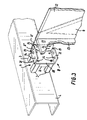
- the suspension system 1 further comprises the suspension bracket 8, which is seen indicated partly in fig. 1 but further in perspective in fig. 3.
- This suspension bracket 8 comprises the second suspension element 10 and a first means 9 for mounting the suspension bracket 8 on the vehicle, preferably on the chassis frame 4 of the vehicle.
- the second suspension element 10 comprises two angled plate pieces 11", 18, the one said plate piece 11" being placed parallel with the first suspension element's plate piece 11', and said second plate piece 18 being placed parallel with the rear 13 of the transport case.
- the second suspension element 10 is produced from a single plate piece which is subsequently bent to form the two respective plate pieces 11", 18. Thereafter, the second plate piece 18 is bent in the formation of two angle pieces 21, whereby the second suspension element 10 more or less forms a partly closed box with two adjoining openings facing towards the transport case 2. Between the angle pieces 21 and the first plate piece 11", a gap 19 is provided whereby the tightening of the first plate piece 11" and the first suspension element's plate piece 11' is made easier.
- the mounting is effected by means of the first means 9, said first means 9 comprising at least one distance piece, which is bolted fast via through-going holes 14 both in the plate piece 18 and through-going holes 14 in the chassis frame 4.
- the number of distance pieces 9 can vary, and in this example embodiment use is made of two, where these are placed substantially in connection with the corner areas of the plate piece.
- the distance piece 9 comprises two spacing tubes 3 which are held together by a bar 11 to form one unit, whereby the mounting is made easier and the spacing tubes 3 are prevented from turning around.
- the spacing tubes 3 consist of rectangular tubes so that they are able to be used with through-holes of different dimensions.
- the bar 11 placed between the spacing tubes 3 abuts against the second plate piece 18, whereby the bar 11 serves as reinforcement for the suspension bracket 8.
- two suspension brackets 8 can be placed at the side of each other, where these are held together by a reinforcement 25.
- the reinforcement 25 is placed in connection with the outer side of the suspension element's angle piece 21.
- the reinforcement 25 can be placed on a single angle piece 21 or on both (see fig. 4), and in such a manner that the limiting edge from the reinforcement 25, respectively the angle piece 21, lies flush in orientation towards the transport case.
- a reinforcement 25 is seen in detail in fig. 6.
- the reinforcement 25 thus comprises a plate which has transverse sides which slope towards the distance piece, and the long side of the plate, oriented towards the transport case, is provided with through-going holes 14 at equal intervals.
- the length of the reinforcement 25 can vary (marked with the stippled line), and can thus be chosen on the basis of the dimensions of the transport case and respectively the distance between the holes in the chassis frame 4.
- the second suspension element 10 can be narrow rectangular, but can also be broader and thus have the through-going holes 14 in the second plate piece 18 placed at a greater distance from the chassis frame. Which suspension bracket is chosen will thus depend on the given vehicle.
- Fig. 4 shows a further detail view of the suspension bracket 8, which as mentioned comprises the plate-shaped second suspension element 10 in which at least four and preferable eight holes 14 are provided, and where in distance and number these correspond to the number in the first suspension element 7.
- the suspension bracket 8 further comprises said first means 9 for the mounting of the suspension bracket 8 on the chassis frame 4, and where as shown in fig. 3 it comprises said distance piece which is mounted on the second plate piece 18 of the suspension bracket.
- a plate/an angle profile 26 between the one spacing tube 3 and the chassis frame 4 there is placed a plate/an angle profile 26.
- the profile is a reinforcement of the chassis frame, which is used especially where this is heavily loaded, which is the case under the saddle, which supports the foremost part of the semi-trailer.
- the plate 26 is bent in the formation of two angled plate parts, where the one plate part 23 is placed between the spacing tube 3 and the chassis frame 4, while the other plate part 24 extends up over the reinforcement 25 and hereby covers the whole of the spacing tube 3.
- the second plate part 24 thus serves almost as a "packing" for the whole of the distance piece 9.
- the configuration of the plate 26 is therefore not important and it can assume any shape.
- the frame 6 itself is built up from components, namely three different types of profiles which are provided in one piece, whereby time is saved in the assembly of the profiles 15,16,17, while at the same time no joints arise which could become loose during use/transport.
- the frame 6 is built into the case under the outer cladding, in that the case is built up of plates of wood-fibre with an external cladding of thin metal sheets.
- the interface part i.e. the coupling between the second suspension element 10 and the first suspension element 7, extends out only on the rear of the case, so that both the bottom and the sides are executed with smooth cladding sheets.
- the length of the first profile type 15 varies with the depth of the case
- the length of the second profile type 17, which forms the rear cladding part and which supports the interface part, i.e. the first suspension element 7, varies with the height of the case
- the third profile type 16 varies with the height of the case.
- the suspension system 1 is thus made up of standardised components which are welded together into a bracket which fits the actual make of vehicle, and which conforms to that distance which is desired between chassis and case.
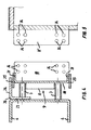
- Fig. 8 shows a second example embodiment of a suspension system 1 comprising a frame 6 and a suspension bracket 8.
- first suspension element 7 On the frame 6 there is mounted a first suspension element 7, said first suspension element 7 preferably being configured as a plate piece 11' and in a manner such as this is also shown in detail in fig. 10. In the plate piece 11' there are through-going holes 14, so that a bolt can be passed through these for the fastening of the first suspension element 7 to the second suspension element 10, as will be described in the following.
- the first suspension element 7 constitutes an integral part of the frame's rear cladding, so that this stands substantially at right-angles to the rear 13 and is plane-parallel with the side pieces 12 of the transport case, and is placed in an area where the rear piece and side piece adjoin. There are thus preferably provided a total of two first suspension elements 7 with a distance between them corresponding to the breadth of the case.
- the suspension system 1 further comprises the suspension bracket 8, which comprises a first means 9 for the mounting of the suspension bracket 8 on the vehicle, preferably on its chassis frame 4.
- the mounting can be effected with a plane-parallel plate piece 18 which can be bolted fast via through-going holes 14 in both the plate piece 18 and the chassis frame.
- the first means 9 will thus comprise two distance pieces provided by the plate piece 18 itself.
- angle pieces 21 can be mounted, such as this is also seen in fig. 3, which are mounted on a chassis frame, but where two distance pieces comprising chassis clamping plates 20 are placed between the angle piece 21 and the chassis frame.
- Such a chassis clamping plate 20 is shown in detail in fig. 11.
- the chassis clamping plate 20 thus has elongated holes 14, designated cut-outs 22, which make it possible for the plate 18 to be displaced in these.
- the plate piece 18 can be welded to the angle pieces 21, said angle pieces 21 extending with their one leg down into a gutter formed between the chassis clamping plate 20 and the chassis.
- the system can also be configured by the plate piece 18 quite simply being bent into a U-shape at the top, and thus being mounted on the chassis frame itself by an ordinary suspension system. What is important is that from and at right-angles to this plate piece 18 there extends an additional plate piece 11" which is at right-angles to the rear piece, and which has through-going holes 14 at intervals corresponding to the holes which are seen in the first suspension element 7.
- the second suspension element 10 can be narrow rectangular, but can also be broader and thus have the through-going holes placed at a greater distance from the chassis frame. Which suspension bracket is chosen will thus depend on the selected vehicle.
- Fig. 9 shows a further detail view of the suspension bracket 8, which as mentioned comprises the plate-shaped second suspension element 10 in which at least two and preferably four holes 14 are provided, and where in distance and number these correspond to the number in the first suspension element 7.
- the suspension bracket 8 further comprises first means 9 for mounting in the chassis frame 4, and where as shown in fig. 9 these comprise a chassis clamping plate 20 which are placed both at the top and at the bottom, and which lie at a distance to the chassis frame itself, whereby a gutter is created which an angle-iron can pass down into, said angle-iron thus constituting an integral part of or being welded onto the second suspension element 10 itself, which in this case is plate-shaped.
- the frame itself is built up from components, namely three different profile types, which can be joined together to form a finished suspension by assembly with screws or by welding.
- This frame is built into the case under the outer cladding, in that the case is built up of plates of wood-fibre with an external cladding of thin sheet metal plates.
- the interface part i.e. the coupling between the second suspension element 10 and the first suspension element 7, extends out only on the rear of the case, so that both the bottom and sides are executed with smooth cladding sheets.
- the length of the first profile type 15 varies with the depth of the case
- the length of the second profile type 17, which forms the rear cladding part and which supports the interface part, i.e. the first suspension element 7, varies with the height of the case
- the third profile type 16 varies with the height of the case.
- the invention is not limited to the present example embodiment, in that it must be noted that the important aspect of the invention is the standardised dividing surface, also called the interface, which arises via the coupling of the first suspension element together with the second suspension element, and where these have identical through-going holes for an easier mounting and coupling together of the second suspension element with the first means.
- the coupling together can possibly be effected by means of welds.
Landscapes
- Engineering & Computer Science (AREA)
- Transportation (AREA)
- Mechanical Engineering (AREA)
- Body Structure For Vehicles (AREA)
- Fittings On The Vehicle Exterior For Carrying Loads, And Devices For Holding Or Mounting Articles (AREA)
- Container Filling Or Packaging Operations (AREA)
- Chain Conveyers (AREA)
- Automatic Assembly (AREA)
Abstract
Description
- The invention relates to a suspension system for mounting transport cases on vehicles, comprising means for mounting/suspension of the cases, said means comprising a frame for the securing of the cases and at least one suspension element, said frame comprising at least one first suspension element for coupling together with/mounting on an item, and said suspension bracket comprising first means for mounting of the suspension bracket on the vehicle.
- In step with the efforts which are made in connection with the better utilisation of the cargo spaces on trucks for profitable loads, the possibilities for creating space for the driver and the vehicle's own equipment are restricted. As an example it can be mentioned that it is desirable to have a bed length of 16 metres on a trailer which by legislature is limited to 18 metres, which leaves place for a driver's cabin of only two metres. At the same time herewith, the need is increased for carrying auxiliary equipment and comfort equipment which shall be stored in closed compartments, for example equipment such as refrigerators for food, space for extra footwear, for snow-chains, for spare wheels, for extra batteries, for a mini-kitchen, for washbasins etc.
- The need is met by mounting so-called transport cases on the trucks, so that the cargo space and driver's cabin are held free of these extra items. The cases are placed outside the chassis frame and under the bed of the vehicle.
- The cases are supplied in many different configurations, depending on the things it is desired to carry, and are suitable for the actual space conditions, which can be very restrictive on the vehicles.
- The suspensions or the frames for securing the cases on the vehicle are at present manufactured as a one-off production, and are intended only for the actual cases on the relevant vehicle, in that vehicles of many different makes and many case dimensions are involved.
- For example, from EP 0,872,372 there is known a suspension system comprising a holder system/frame for the securing of the items and a suspension bracket comprising two separate suspension elements, a lower suspension element and an upper suspension element, both of which are mounted on the chassis frame of the vehicle by means of bolts.
- The holder system/frame comprises a strap which is an integral part of the actual item which is to be suspended, and is mounted on the upper suspension element by means of a plate which is an integral part of the holder system/frame itself. The item thus comprises individual item sections which must surround the holder system/frame.
- The upper suspension element comprises a bent plate comprising two surfaces which are fastened to the chassis frame, and between the two surfaces an outwardly-extending inclined surface on which the holder system/frame's integrated plate is fastened. The lower suspension element comprises a substantially C-shaped plate, the opening in which is oriented towards the items.
- When an item is thus placed in connection with the holder system/frame, the lower suspension element will serve as a buffer for the item, whereby the suspension element does not have any distinct suspension effect.
- The construction and the configuration of the holder system/frame is encumbered with a number of disadvantages, in that it is integrated in the actual item and thus constitutes assemblies for the individual item sections. This will mean that when the holder system/frame or other parts are to be replaced/repaired, the whole of the item must be dismantled, which is troublesome and time-consuming. Moreover, the separate suspension elements can give rise to the holes already drilled in the chassis frame not necessarily being of the right fit, or that they can be used, whereby the suspension elements will be dependent upon the actual make of vehicle. Furthermore, the fastening of the holder comprises only two suspension elements, which means that it is not possible for the positioning of the holder to be adjusted in the horizontal direction.
- The object of the present invention is thus to provide a standardised, prefabricated suspension system with which it is possible to piece together a suspension which fits a given case on a given vehicle, and whereby the workshop time for mounting of the case is considerably reduced, i.e. from 2 days to approx. half an hour.
- With the system, there is thus achieved a form of standardised dividing surface, so that the frames which are mounted on the case are dependent only on the case dimensions, and the frames which are mounted on the chassis of the vehicle are dependent only on the make of the vehicle.
- This object is achieved with a suspension system of the kind disclosed in the introduction, and also where the means further comprise second suspension elements for coupling to/mounting on the first suspension element, said first suspension element being a plate piece placed plane-parallel with the sides of the transport case, and preferably at right-angles to the rear of the case, and where said second suspension element comprises two plate pieces at angles in relation to each other, one of said plate pieces being placed parallel with the first suspension element's plate piece, and the second of said plate pieces being placed parallel with the rear of the case and in orientation with the vehicle, said suspension element also being connected to the first means.
- The invention thus comprises a frame which surrounds the transport case itself, and where to the frame there is connected a so-called first suspension element which is typically configured as a bracket in which there are mounting holes. On the chassis of the vehicle there is now secured a so-called suspension bracket, which via one or more distance pieces is typically mounted on the chassis by means of bolts through through-going holes in the distance pieces.
- In addition, the suspension bracket has a plate piece extending at right-angles out from the chassis, which plate piece also comprises holes which correspond to the holes which are in the suspension element on the frame itself. By inserting bolts through the holes in the first suspension element and the second suspension element, said holes lying substantially opposite each other, a coupling of the case to the vehicle itself is achieved. The coupling can also be effected by means of welding.
- In that the system comprises an intermediate piece, i.e. the second suspension element, it is possible to adjust the distance between side piece and transport case so that the system can be used for all makes of vehicles.
- The suspension element, which is expedient in the sense that it thus comes to lie flush with the side end of the case, and by providing the second suspension element, these suspension elements can be coupled against each other by a simple abutment of their surfaces.
- By providing a suspension system according to the invention and as disclosed in
claim - By providing a suspension system according to the invention and as disclosed in
claim 4, a stable mounting of the cases on the chassis frame is achieved. - By providing a suspension system according to the invention and as further disclosed in
claim 5, it is achieved that there is sufficient space for mounting on the chassis frame, where there are already many fittings. - By providing a suspension system according to the invention and as further disclosed in
claim 6, it is achieved that the unit which shall house the case can be built up of few components, which can be assembled to form a finished suspension by means of screws and/or welding. - By providing a suspension system according to the invention and as disclosed in
claim 7, it is achieved that the frame is not disposed to become loose during use/transport, and time is saved in not having to assemble individual parts. The frame can expediently be produced by laser cutting. - The profiles constituting the frame can expediently be built into the case itself under the outer cladding, in that the cases are typically built up of wood-fibre plates with an external cladding of thin metal sheets.
- The first and the second suspension elements thus extend only out of the rear of the case, so that both the bottom and the sides are executed with smooth cladding sheets.
- The invention will now be explained in more detail with reference to the drawing, where
- fig. 1
- shows a first example embodiment of a suspension system in relation to a chassis frame seen from the side, and where a case is mounted,
- fig. 2
- shows a second example embodiment of a frame,
- fig. 3
- shows the suspension system shown in fig. 1, seen in perspective and mounted on a chassis frame,
- fig. 4
- shows the suspension bracket for the suspension system shown in fig. 1,
- fig. 5
- shows the first suspension element for the suspension bracket shown in fig. 1, and mounted on or constituting an integral part of the frame,
- fig. 6
- shows a reinforcement for the suspension bracket of the suspension system shown in fig. 1,
- fig. 7
- shows a distance piece for the suspension bracket of the suspension system shown in fig. 1,
- fig. 8
- shows a second example embodiment of a suspension system seen in perspective and mounted on a chassis frame,
- fig. 9
- shows the suspension bracket for a suspension system shown in fig. 6,
- fig. 10
- shows the first suspension element mounted on or constituting an integral part of the frame, and
- fig. 11
- shows a chassis clamping plate for the suspension bracket of the suspension system shown in fig. 1.
- Fig. 1 shows a first example embodiment of the suspension system 1, comprising a
frame 6, saidframe 6 comprising three types ofprofiles first profile type 15 forms the bottom, thesecond profile type 17 forms a vertical wall piece, while thethird profile piece 16 forms a connection between the first 15 and thesecond profile piece 17. Theprofile types third profile type 16 is mounted in the upper part of thesecond profile piece 17 and approximately in the centre of thefirst profile piece 15, whereby the longitudinal axis of thethird profile piece 16 forms an angle V of approx. 45° with the horizontal plane. Thetransport case 2 itself is mounted in this profile system. - In connection with the
first profile type 15, tworeinforcing profiles 5 are provided on the underside of this and oriented away from thetransport case 2. The number of reinforcingprofiles 5 can vary, or they can be completely omitted, but are expedient in the mounting of anadditional transport case 2 which can be placed under the first, in that the reinforcingprofiles 5 partly create "air" between thetransport cases 2 and partly guide theunderlying transport case 2 when this is being mounted. - A
first suspension element 7 is mounted on theframe 6, saidfirst suspension element 7 preferably being configured as a plate piece 11', and in a manner such as otherwise shown in detail in fig. 5. In the plate piece 11' there are through-goingholes 14, so that a bolt can pass through these for the fastening of thefirst suspension element 7 to thesecond suspension element 10, such as will be described in the following. - The
first suspension element 7 constitutes an integral part of the rear cladding of the frame, so that it stands substantially at right-angles to the rear 13 and is plane-parallel with theside pieces 12 of the transport case, and is disposed in an area where the rear piece and side piece meet. There is thus preferably placed a total of twofirst suspension elements 7 with a distance between them corresponding to the breadth of the case. - The suspension system 1 further comprises the
suspension bracket 8, which is seen indicated partly in fig. 1 but further in perspective in fig. 3. Thissuspension bracket 8 comprises thesecond suspension element 10 and afirst means 9 for mounting thesuspension bracket 8 on the vehicle, preferably on thechassis frame 4 of the vehicle. - The
second suspension element 10 comprises twoangled plate pieces 11", 18, the one saidplate piece 11" being placed parallel with the first suspension element's plate piece 11', and saidsecond plate piece 18 being placed parallel with the rear 13 of the transport case. Thesecond suspension element 10 is produced from a single plate piece which is subsequently bent to form the tworespective plate pieces 11", 18. Thereafter, thesecond plate piece 18 is bent in the formation of twoangle pieces 21, whereby thesecond suspension element 10 more or less forms a partly closed box with two adjoining openings facing towards thetransport case 2. Between theangle pieces 21 and thefirst plate piece 11", agap 19 is provided whereby the tightening of thefirst plate piece 11" and the first suspension element's plate piece 11' is made easier. - As mentioned, the mounting is effected by means of the
first means 9, said first means 9 comprising at least one distance piece, which is bolted fast via through-goingholes 14 both in theplate piece 18 and through-goingholes 14 in thechassis frame 4. - The number of
distance pieces 9 can vary, and in this example embodiment use is made of two, where these are placed substantially in connection with the corner areas of the plate piece. As shown in fig. 7, thedistance piece 9 comprises twospacing tubes 3 which are held together by abar 11 to form one unit, whereby the mounting is made easier and thespacing tubes 3 are prevented from turning around. In this connection, thespacing tubes 3 consist of rectangular tubes so that they are able to be used with through-holes of different dimensions. Thebar 11 placed between thespacing tubes 3 abuts against thesecond plate piece 18, whereby thebar 11 serves as reinforcement for thesuspension bracket 8. - If the distance between the through-going
holes 14 in thesecond plate piece 18 is not coincident with the through-going holes in thechassis frame 4, with the result that thesuspension bracket 8 can not be mounted securely on thechassis frame 4, twosuspension brackets 8 can be placed at the side of each other, where these are held together by areinforcement 25. Thereinforcement 25 is placed in connection with the outer side of the suspension element'sangle piece 21. Thereinforcement 25 can be placed on asingle angle piece 21 or on both (see fig. 4), and in such a manner that the limiting edge from thereinforcement 25, respectively theangle piece 21, lies flush in orientation towards the transport case. Areinforcement 25 is seen in detail in fig. 6. - The
reinforcement 25 thus comprises a plate which has transverse sides which slope towards the distance piece, and the long side of the plate, oriented towards the transport case, is provided with through-goingholes 14 at equal intervals. The length of thereinforcement 25 can vary (marked with the stippled line), and can thus be chosen on the basis of the dimensions of the transport case and respectively the distance between the holes in thechassis frame 4. - As shown in fig. 3, the
second suspension element 10 can be narrow rectangular, but can also be broader and thus have the through-goingholes 14 in thesecond plate piece 18 placed at a greater distance from the chassis frame. Which suspension bracket is chosen will thus depend on the given vehicle. - Fig. 4 shows a further detail view of the
suspension bracket 8, which as mentioned comprises the plate-shapedsecond suspension element 10 in which at least four and preferable eightholes 14 are provided, and where in distance and number these correspond to the number in thefirst suspension element 7. - The
suspension bracket 8 further comprises said first means 9 for the mounting of thesuspension bracket 8 on thechassis frame 4, and where as shown in fig. 3 it comprises said distance piece which is mounted on thesecond plate piece 18 of the suspension bracket. - As will also be seen from fig. 4 and fig. 1, between the one
spacing tube 3 and thechassis frame 4 there is placed a plate/anangle profile 26. The profile is a reinforcement of the chassis frame, which is used especially where this is heavily loaded, which is the case under the saddle, which supports the foremost part of the semi-trailer. In this example embodiment, theplate 26 is bent in the formation of two angled plate parts, where the oneplate part 23 is placed between the spacingtube 3 and thechassis frame 4, while theother plate part 24 extends up over thereinforcement 25 and hereby covers the whole of thespacing tube 3. Thesecond plate part 24 thus serves almost as a "packing" for the whole of thedistance piece 9. The configuration of theplate 26 is therefore not important and it can assume any shape. - The
frame 6 itself is built up from components, namely three different types of profiles which are provided in one piece, whereby time is saved in the assembly of theprofiles - The
frame 6 is built into the case under the outer cladding, in that the case is built up of plates of wood-fibre with an external cladding of thin metal sheets. The interface part, i.e. the coupling between thesecond suspension element 10 and thefirst suspension element 7, extends out only on the rear of the case, so that both the bottom and the sides are executed with smooth cladding sheets. - The length of the
first profile type 15 varies with the depth of the case, the length of thesecond profile type 17, which forms the rear cladding part and which supports the interface part, i.e. thefirst suspension element 7, varies with the height of the case, while thethird profile type 16 varies with the height of the case. - The suspension system 1 is thus made up of standardised components which are welded together into a bracket which fits the actual make of vehicle, and which conforms to that distance which is desired between chassis and case.
- Fig. 8 shows a second example embodiment of a suspension system 1 comprising a
frame 6 and asuspension bracket 8. - On the
frame 6 there is mounted afirst suspension element 7, saidfirst suspension element 7 preferably being configured as a plate piece 11' and in a manner such as this is also shown in detail in fig. 10. In the plate piece 11' there are through-goingholes 14, so that a bolt can be passed through these for the fastening of thefirst suspension element 7 to thesecond suspension element 10, as will be described in the following. - The
first suspension element 7 constitutes an integral part of the frame's rear cladding, so that this stands substantially at right-angles to the rear 13 and is plane-parallel with theside pieces 12 of the transport case, and is placed in an area where the rear piece and side piece adjoin. There are thus preferably provided a total of twofirst suspension elements 7 with a distance between them corresponding to the breadth of the case. - The suspension system 1 further comprises the
suspension bracket 8, which comprises afirst means 9 for the mounting of thesuspension bracket 8 on the vehicle, preferably on itschassis frame 4. The mounting can be effected with a plane-parallel plate piece 18 which can be bolted fast via through-goingholes 14 in both theplate piece 18 and the chassis frame. The first means 9 will thus comprise two distance pieces provided by theplate piece 18 itself. Alternatively,angle pieces 21 can be mounted, such as this is also seen in fig. 3, which are mounted on a chassis frame, but where two distance pieces comprisingchassis clamping plates 20 are placed between theangle piece 21 and the chassis frame. Such achassis clamping plate 20 is shown in detail in fig. 11. - The
chassis clamping plate 20 thus has elongatedholes 14, designated cut-outs 22, which make it possible for theplate 18 to be displaced in these. Alternatively, theplate piece 18 can be welded to theangle pieces 21, saidangle pieces 21 extending with their one leg down into a gutter formed between thechassis clamping plate 20 and the chassis. Alternatively, the system can also be configured by theplate piece 18 quite simply being bent into a U-shape at the top, and thus being mounted on the chassis frame itself by an ordinary suspension system. What is important is that from and at right-angles to thisplate piece 18 there extends anadditional plate piece 11" which is at right-angles to the rear piece, and which has through-goingholes 14 at intervals corresponding to the holes which are seen in thefirst suspension element 7. - As shown in fig. 8, the
second suspension element 10 can be narrow rectangular, but can also be broader and thus have the through-going holes placed at a greater distance from the chassis frame. Which suspension bracket is chosen will thus depend on the selected vehicle. - Fig. 9 shows a further detail view of the
suspension bracket 8, which as mentioned comprises the plate-shapedsecond suspension element 10 in which at least two and preferably fourholes 14 are provided, and where in distance and number these correspond to the number in thefirst suspension element 7. - The
suspension bracket 8 further comprises first means 9 for mounting in thechassis frame 4, and where as shown in fig. 9 these comprise achassis clamping plate 20 which are placed both at the top and at the bottom, and which lie at a distance to the chassis frame itself, whereby a gutter is created which an angle-iron can pass down into, said angle-iron thus constituting an integral part of or being welded onto thesecond suspension element 10 itself, which in this case is plate-shaped. - The frame itself is built up from components, namely three different profile types, which can be joined together to form a finished suspension by assembly with screws or by welding. This frame is built into the case under the outer cladding, in that the case is built up of plates of wood-fibre with an external cladding of thin sheet metal plates. The interface part, i.e. the coupling between the
second suspension element 10 and thefirst suspension element 7, extends out only on the rear of the case, so that both the bottom and sides are executed with smooth cladding sheets. - The length of the
first profile type 15 varies with the depth of the case, the length of thesecond profile type 17, which forms the rear cladding part and which supports the interface part, i.e. thefirst suspension element 7, varies with the height of the case, while thethird profile type 16 varies with the height of the case. - The invention is not limited to the present example embodiment, in that it must be noted that the important aspect of the invention is the standardised dividing surface, also called the interface, which arises via the coupling of the first suspension element together with the second suspension element, and where these have identical through-going holes for an easier mounting and coupling together of the second suspension element with the first means. The coupling together can possibly be effected by means of welds.
Claims (7)
- Suspension system (1) for mounting transport cases (2) on vehicles, comprising means for mounting/suspension of the cases (2), said means comprising a frame (6) for securing the cases (2) and at least one suspension bracket (8), said frame (6) comprising at least one first suspension element (7) for coupling together with/mounting on an item, and said suspension bracket (8) comprising first means (9) for the mounting of the suspension bracket (8) on the vehicle, characterised in that the means further comprise second suspension elements (10) for coupling together with/mounting on the first suspension element (7), said first suspension element (7) being a plate piece (11') placed plane-parallel with the sides of the transport case and preferably at right-angles from the rear (13) of the case, and said second suspension element (10) comprising two plate pieces (11", 18) angled in relation to each other, where one said plate piece (11") is placed parallel with the plate piece (11') of the first suspension element (7), and the second said plate piece (18) is placed parallel with the rear (13) of the case and in orientation with the vehicle, said suspension element (10) being further connected to the first means (9).
- Suspension system (1) according to claim 1, characterised in that the first and the second suspension elements (7,10) comprise through-going holes (14), at least two in each element, said through-going holes (14) being placed at identical intervals in the first and second suspension elements (7,10).
- Suspension system (1) according to claim 2, characterised in that the through-going holes (14) are provided in the plate pieces (11', 11", 18).
- Suspension system (1) according to any of the foregoing claims, characterised in that the suspension system (1) comprises at least two first (7) and two second suspension elements (10) placed at a distance from each other, and corresponding substantially to the breadth of the transport case (2).
- Suspension system (1) according to any of the foregoing claims, charact erised in that the first means (9) comprise at least one preferably two distance pieces and a corresponding number of bolts (19) for the fastening of the plate piece (18) to the vehicle.
- Suspension system according to any of the foregoing claims, charact erised in that the frame (6) comprises at least three different profile types (15,16,17), and means for the assembly of these.
- Suspension system (1) according to claims 1 - 5, characterised in that the frame (6) comprises at least three different profile types (15, 16, 17), said profile types (15, 16,17) being provided as one element.
Priority Applications (1)
| Application Number | Priority Date | Filing Date | Title |
|---|---|---|---|
| DK01610089T DK1182079T3 (en) | 2000-08-25 | 2001-08-23 | Suspension system for mounting transport cabinets on vehicles |
Applications Claiming Priority (2)
| Application Number | Priority Date | Filing Date | Title |
|---|---|---|---|
| DK200001261A DK200001261A (en) | 2000-08-25 | 2000-08-25 | Suspension system for mounting transport cabinets on vehicles |
| DK200001261 | 2000-08-25 |
Publications (3)
| Publication Number | Publication Date |
|---|---|
| EP1182079A2 true EP1182079A2 (en) | 2002-02-27 |
| EP1182079A3 EP1182079A3 (en) | 2004-01-28 |
| EP1182079B1 EP1182079B1 (en) | 2005-04-27 |
Family
ID=8159675
Family Applications (1)
| Application Number | Title | Priority Date | Filing Date |
|---|---|---|---|
| EP01610089A Expired - Lifetime EP1182079B1 (en) | 2000-08-25 | 2001-08-23 | Suspension system for mounting transport cases on vehicles |
Country Status (4)
| Country | Link |
|---|---|
| EP (1) | EP1182079B1 (en) |
| AT (1) | ATE294080T1 (en) |
| DE (1) | DE60110331T2 (en) |
| DK (1) | DK200001261A (en) |
Cited By (1)
| Publication number | Priority date | Publication date | Assignee | Title |
|---|---|---|---|---|
| EP2130747A2 (en) * | 2008-06-06 | 2009-12-09 | J. Eberspächer GmbH Co. KG | Mounting device for a vehicle mounted part |
Citations (1)
| Publication number | Priority date | Publication date | Assignee | Title |
|---|---|---|---|---|
| EP0872372A1 (en) | 1997-04-17 | 1998-10-21 | United Parts Läreda AB | Fuel tank |
Family Cites Families (2)
| Publication number | Priority date | Publication date | Assignee | Title |
|---|---|---|---|---|
| SE469377B (en) * | 1991-12-23 | 1993-06-28 | Saab Scania Ab | BRAIN MAINTENANCE ARRANGEMENTS FOR MOTOR VEHICLES |
| DE19814975B4 (en) * | 1998-04-03 | 2004-02-12 | Man Nutzfahrzeuge Ag | Carrier system for commercial vehicles |
-
2000
- 2000-08-25 DK DK200001261A patent/DK200001261A/en not_active Application Discontinuation
-
2001
- 2001-08-23 DE DE60110331T patent/DE60110331T2/en not_active Expired - Lifetime
- 2001-08-23 AT AT01610089T patent/ATE294080T1/en not_active IP Right Cessation
- 2001-08-23 EP EP01610089A patent/EP1182079B1/en not_active Expired - Lifetime
Patent Citations (1)
| Publication number | Priority date | Publication date | Assignee | Title |
|---|---|---|---|---|
| EP0872372A1 (en) | 1997-04-17 | 1998-10-21 | United Parts Läreda AB | Fuel tank |
Cited By (3)
| Publication number | Priority date | Publication date | Assignee | Title |
|---|---|---|---|---|
| EP2130747A2 (en) * | 2008-06-06 | 2009-12-09 | J. Eberspächer GmbH Co. KG | Mounting device for a vehicle mounted part |
| EP2130747A3 (en) * | 2008-06-06 | 2010-07-07 | J. Eberspächer GmbH Co. KG | Mounting device for a vehicle mounted part |
| US8413940B2 (en) | 2008-06-06 | 2013-04-09 | Eberspächer Exhaust Technology GmbH & Co. KG | Holding device for an add-on part of a motor vehicle |
Also Published As
| Publication number | Publication date |
|---|---|
| EP1182079A3 (en) | 2004-01-28 |
| DE60110331T2 (en) | 2006-02-23 |
| DE60110331D1 (en) | 2005-06-02 |
| ATE294080T1 (en) | 2005-05-15 |
| EP1182079B1 (en) | 2005-04-27 |
| DK200001261A (en) | 2002-02-26 |
Similar Documents
| Publication | Publication Date | Title |
|---|---|---|
| US10272859B2 (en) | Trailer with rear impact guard | |
| US7665800B2 (en) | Truck box space frame | |
| US5567005A (en) | Car body work sub-frame mounting structure | |
| US11358655B2 (en) | Modular truck bed | |
| US7766416B2 (en) | Wall structure of vehicle frame between cab and load-carrying bed | |
| CA1307554C (en) | Truck body deck mount | |
| US4267948A (en) | Cargo carrier | |
| US5725137A (en) | Carrier rack and rack retainer | |
| US20030189359A1 (en) | Reinforcing bracket for trailer-frame butt joints | |
| US20080007096A1 (en) | Multi-Function Cross Members for Truck Frames | |
| US7588285B2 (en) | Cargo box for pickup truck and method for making same | |
| US5588693A (en) | Modular truck cargo area body | |
| US6742832B1 (en) | Vehicle bed assembly and a method for making a vehicle bed assembly | |
| WO2000061424A1 (en) | A beam connection | |
| US20070007759A1 (en) | Trailer having reduced weight beam construction | |
| US5393096A (en) | Suspension frame bracket | |
| WO1999059830A1 (en) | Vehicle trailer frame cross member/suspension assembly mount | |
| US7191567B2 (en) | Floor frame structure for a manufactured home | |
| CA1289592C (en) | Floor subframe for cargo truck sleeper cab | |
| BRPI1102739A2 (en) | support frame for lateral attachment of complementary parts to a longitudinal support of a utility vehicle support structure | |
| EP1182079B1 (en) | Suspension system for mounting transport cases on vehicles | |
| EP0784004A1 (en) | Body assembly | |
| US20220194298A1 (en) | Sub-Frame and Step Assembly for Truck | |
| US20200269921A1 (en) | Sub-Frame and Step Assembly for Truck | |
| US7144041B2 (en) | Aluminum hanger and hanger assembly |
Legal Events
| Date | Code | Title | Description |
|---|---|---|---|
| PUAI | Public reference made under article 153(3) epc to a published international application that has entered the european phase |
Free format text: ORIGINAL CODE: 0009012 |
|
| AK | Designated contracting states |
Kind code of ref document: A2 Designated state(s): AT BE CH CY DE DK ES FI FR GB GR IE IT LI LU MC NL PT SE TR |
|
| AX | Request for extension of the european patent |
Free format text: AL;LT;LV;MK;RO;SI |
|
| PUAL | Search report despatched |
Free format text: ORIGINAL CODE: 0009013 |
|
| AK | Designated contracting states |
Kind code of ref document: A3 Designated state(s): AT BE CH CY DE DK ES FI FR GB GR IE IT LI LU MC NL PT SE TR |
|
| AX | Request for extension of the european patent |
Extension state: AL LT LV MK RO SI |
|
| RIC1 | Information provided on ipc code assigned before grant |
Ipc: 7B 60R 9/00 B Ipc: 7B 60P 1/00 A Ipc: 7B 60K 15/067 B |
|
| 17P | Request for examination filed |
Effective date: 20040728 |
|
| GRAP | Despatch of communication of intention to grant a patent |
Free format text: ORIGINAL CODE: EPIDOSNIGR1 |
|
| AKX | Designation fees paid |
Designated state(s): AT BE CH CY DE DK ES FI FR GB GR IE IT LI LU MC NL PT SE TR |
|
| GRAS | Grant fee paid |
Free format text: ORIGINAL CODE: EPIDOSNIGR3 |
|
| GRAA | (expected) grant |
Free format text: ORIGINAL CODE: 0009210 |
|
| AK | Designated contracting states |
Kind code of ref document: B1 Designated state(s): AT BE CH CY DE DK ES FI FR GB GR IE IT LI LU MC NL PT SE TR |
|
| PG25 | Lapsed in a contracting state [announced via postgrant information from national office to epo] |
Ref country code: IT Free format text: LAPSE BECAUSE OF FAILURE TO SUBMIT A TRANSLATION OF THE DESCRIPTION OR TO PAY THE FEE WITHIN THE PRESCRIBED TIME-LIMIT;WARNING: LAPSES OF ITALIAN PATENTS WITH EFFECTIVE DATE BEFORE 2007 MAY HAVE OCCURRED AT ANY TIME BEFORE 2007. THE CORRECT EFFECTIVE DATE MAY BE DIFFERENT FROM THE ONE RECORDED. Effective date: 20050427 Ref country code: BE Free format text: LAPSE BECAUSE OF FAILURE TO SUBMIT A TRANSLATION OF THE DESCRIPTION OR TO PAY THE FEE WITHIN THE PRESCRIBED TIME-LIMIT Effective date: 20050427 Ref country code: AT Free format text: LAPSE BECAUSE OF FAILURE TO SUBMIT A TRANSLATION OF THE DESCRIPTION OR TO PAY THE FEE WITHIN THE PRESCRIBED TIME-LIMIT Effective date: 20050427 Ref country code: CH Free format text: LAPSE BECAUSE OF FAILURE TO SUBMIT A TRANSLATION OF THE DESCRIPTION OR TO PAY THE FEE WITHIN THE PRESCRIBED TIME-LIMIT Effective date: 20050427 Ref country code: FI Free format text: LAPSE BECAUSE OF FAILURE TO SUBMIT A TRANSLATION OF THE DESCRIPTION OR TO PAY THE FEE WITHIN THE PRESCRIBED TIME-LIMIT Effective date: 20050427 Ref country code: LI Free format text: LAPSE BECAUSE OF FAILURE TO SUBMIT A TRANSLATION OF THE DESCRIPTION OR TO PAY THE FEE WITHIN THE PRESCRIBED TIME-LIMIT Effective date: 20050427 Ref country code: TR Free format text: LAPSE BECAUSE OF FAILURE TO SUBMIT A TRANSLATION OF THE DESCRIPTION OR TO PAY THE FEE WITHIN THE PRESCRIBED TIME-LIMIT Effective date: 20050427 |
|
| REG | Reference to a national code |
Ref country code: GB Ref legal event code: FG4D |
|
| REG | Reference to a national code |
Ref country code: CH Ref legal event code: EP |
|
| REG | Reference to a national code |
Ref country code: IE Ref legal event code: FG4D |
|
| REF | Corresponds to: |
Ref document number: 60110331 Country of ref document: DE Date of ref document: 20050602 Kind code of ref document: P |
|
| REG | Reference to a national code |
Ref country code: SE Ref legal event code: TRGR |
|
| REG | Reference to a national code |
Ref country code: DK Ref legal event code: T3 |
|
| PG25 | Lapsed in a contracting state [announced via postgrant information from national office to epo] |
Ref country code: GR Free format text: LAPSE BECAUSE OF FAILURE TO SUBMIT A TRANSLATION OF THE DESCRIPTION OR TO PAY THE FEE WITHIN THE PRESCRIBED TIME-LIMIT Effective date: 20050727 |
|
| PG25 | Lapsed in a contracting state [announced via postgrant information from national office to epo] |
Ref country code: ES Free format text: LAPSE BECAUSE OF FAILURE TO SUBMIT A TRANSLATION OF THE DESCRIPTION OR TO PAY THE FEE WITHIN THE PRESCRIBED TIME-LIMIT Effective date: 20050807 |
|
| PG25 | Lapsed in a contracting state [announced via postgrant information from national office to epo] |
Ref country code: GB Free format text: LAPSE BECAUSE OF NON-PAYMENT OF DUE FEES Effective date: 20050823 Ref country code: LU Free format text: LAPSE BECAUSE OF NON-PAYMENT OF DUE FEES Effective date: 20050823 Ref country code: IE Free format text: LAPSE BECAUSE OF NON-PAYMENT OF DUE FEES Effective date: 20050823 Ref country code: CY Free format text: LAPSE BECAUSE OF FAILURE TO SUBMIT A TRANSLATION OF THE DESCRIPTION OR TO PAY THE FEE WITHIN THE PRESCRIBED TIME-LIMIT Effective date: 20050823 |
|
| PG25 | Lapsed in a contracting state [announced via postgrant information from national office to epo] |
Ref country code: MC Free format text: LAPSE BECAUSE OF NON-PAYMENT OF DUE FEES Effective date: 20050831 |
|
| PG25 | Lapsed in a contracting state [announced via postgrant information from national office to epo] |
Ref country code: PT Free format text: LAPSE BECAUSE OF FAILURE TO SUBMIT A TRANSLATION OF THE DESCRIPTION OR TO PAY THE FEE WITHIN THE PRESCRIBED TIME-LIMIT Effective date: 20051010 |
|
| REG | Reference to a national code |
Ref country code: CH Ref legal event code: PL |
|
| PLBE | No opposition filed within time limit |
Free format text: ORIGINAL CODE: 0009261 |
|
| STAA | Information on the status of an ep patent application or granted ep patent |
Free format text: STATUS: NO OPPOSITION FILED WITHIN TIME LIMIT |
|
| ET | Fr: translation filed | ||
| 26N | No opposition filed |
Effective date: 20060130 |
|
| GBPC | Gb: european patent ceased through non-payment of renewal fee |
Effective date: 20050823 |
|
| REG | Reference to a national code |
Ref country code: IE Ref legal event code: MM4A |
|
| PGFP | Annual fee paid to national office [announced via postgrant information from national office to epo] |
Ref country code: DE Payment date: 20100929 Year of fee payment: 10 |
|
| PGFP | Annual fee paid to national office [announced via postgrant information from national office to epo] |
Ref country code: SE Payment date: 20110824 Year of fee payment: 11 Ref country code: FR Payment date: 20110907 Year of fee payment: 11 |
|
| PGFP | Annual fee paid to national office [announced via postgrant information from national office to epo] |
Ref country code: NL Payment date: 20110825 Year of fee payment: 11 |
|
| REG | Reference to a national code |
Ref country code: NL Ref legal event code: V1 Effective date: 20130301 |
|
| REG | Reference to a national code |
Ref country code: SE Ref legal event code: EUG |
|
| PG25 | Lapsed in a contracting state [announced via postgrant information from national office to epo] |
Ref country code: NL Free format text: LAPSE BECAUSE OF NON-PAYMENT OF DUE FEES Effective date: 20130301 Ref country code: SE Free format text: LAPSE BECAUSE OF NON-PAYMENT OF DUE FEES Effective date: 20120824 |
|
| REG | Reference to a national code |
Ref country code: FR Ref legal event code: ST Effective date: 20130430 |
|
| PG25 | Lapsed in a contracting state [announced via postgrant information from national office to epo] |
Ref country code: DE Free format text: LAPSE BECAUSE OF NON-PAYMENT OF DUE FEES Effective date: 20130301 |
|
| PG25 | Lapsed in a contracting state [announced via postgrant information from national office to epo] |
Ref country code: FR Free format text: LAPSE BECAUSE OF NON-PAYMENT OF DUE FEES Effective date: 20120831 |
|
| REG | Reference to a national code |
Ref country code: DE Ref legal event code: R119 Ref document number: 60110331 Country of ref document: DE Effective date: 20130301 |
|
| PGFP | Annual fee paid to national office [announced via postgrant information from national office to epo] |
Ref country code: DK Payment date: 20140819 Year of fee payment: 14 |
|
| REG | Reference to a national code |
Ref country code: DK Ref legal event code: EBP Effective date: 20150831 |
|
| PG25 | Lapsed in a contracting state [announced via postgrant information from national office to epo] |
Ref country code: DK Free format text: LAPSE BECAUSE OF NON-PAYMENT OF DUE FEES Effective date: 20150831 |