EP1182069A1 - Roll formed hardware module - Google Patents
Roll formed hardware module Download PDFInfo
- Publication number
- EP1182069A1 EP1182069A1 EP01202661A EP01202661A EP1182069A1 EP 1182069 A1 EP1182069 A1 EP 1182069A1 EP 01202661 A EP01202661 A EP 01202661A EP 01202661 A EP01202661 A EP 01202661A EP 1182069 A1 EP1182069 A1 EP 1182069A1
- Authority
- EP
- European Patent Office
- Prior art keywords
- panel
- set forth
- longitudinal protrusion
- vehicle door
- arcuate
- Prior art date
- Legal status (The legal status is an assumption and is not a legal conclusion. Google has not performed a legal analysis and makes no representation as to the accuracy of the status listed.)
- Withdrawn
Links
- 238000000034 method Methods 0.000 claims abstract description 41
- 230000008569 process Effects 0.000 claims abstract description 27
- 239000000463 material Substances 0.000 claims abstract description 12
- 230000008859 change Effects 0.000 claims abstract description 4
- 238000007789 sealing Methods 0.000 claims description 17
- XLYOFNOQVPJJNP-UHFFFAOYSA-N water Chemical compound O XLYOFNOQVPJJNP-UHFFFAOYSA-N 0.000 claims description 15
- 239000002184 metal Substances 0.000 claims description 3
- 238000000638 solvent extraction Methods 0.000 claims 2
- 229910000831 Steel Inorganic materials 0.000 description 15
- 239000010959 steel Substances 0.000 description 15
- 230000007246 mechanism Effects 0.000 description 10
- 230000004888 barrier function Effects 0.000 description 8
- 238000004519 manufacturing process Methods 0.000 description 8
- 239000011324 bead Substances 0.000 description 5
- 238000012805 post-processing Methods 0.000 description 4
- 238000013461 design Methods 0.000 description 3
- 238000007726 management method Methods 0.000 description 3
- 238000012360 testing method Methods 0.000 description 3
- 241001074085 Scophthalmus aquosus Species 0.000 description 2
- 239000005357 flat glass Substances 0.000 description 2
- 239000006260 foam Substances 0.000 description 2
- 239000011521 glass Substances 0.000 description 2
- 238000009434 installation Methods 0.000 description 2
- 238000003754 machining Methods 0.000 description 2
- 229910000851 Alloy steel Inorganic materials 0.000 description 1
- 238000010276 construction Methods 0.000 description 1
- 230000003247 decreasing effect Effects 0.000 description 1
- 238000003780 insertion Methods 0.000 description 1
- 230000037431 insertion Effects 0.000 description 1
- 238000012986 modification Methods 0.000 description 1
- 230000004048 modification Effects 0.000 description 1
- 239000004033 plastic Substances 0.000 description 1
- 239000002985 plastic film Substances 0.000 description 1
- 238000004080 punching Methods 0.000 description 1
- 230000009467 reduction Effects 0.000 description 1
- 238000006467 substitution reaction Methods 0.000 description 1
- 238000013024 troubleshooting Methods 0.000 description 1
Images



Classifications
-
- B—PERFORMING OPERATIONS; TRANSPORTING
- B60—VEHICLES IN GENERAL
- B60J—WINDOWS, WINDSCREENS, NON-FIXED ROOFS, DOORS, OR SIMILAR DEVICES FOR VEHICLES; REMOVABLE EXTERNAL PROTECTIVE COVERINGS SPECIALLY ADAPTED FOR VEHICLES
- B60J5/00—Doors
- B60J5/04—Doors arranged at the vehicle sides
- B60J5/042—Reinforcement elements
-
- B—PERFORMING OPERATIONS; TRANSPORTING
- B21—MECHANICAL METAL-WORKING WITHOUT ESSENTIALLY REMOVING MATERIAL; PUNCHING METAL
- B21D—WORKING OR PROCESSING OF SHEET METAL OR METAL TUBES, RODS OR PROFILES WITHOUT ESSENTIALLY REMOVING MATERIAL; PUNCHING METAL
- B21D17/00—Forming single grooves in sheet metal or tubular or hollow articles
- B21D17/04—Forming single grooves in sheet metal or tubular or hollow articles by rolling
-
- B—PERFORMING OPERATIONS; TRANSPORTING
- B21—MECHANICAL METAL-WORKING WITHOUT ESSENTIALLY REMOVING MATERIAL; PUNCHING METAL
- B21D—WORKING OR PROCESSING OF SHEET METAL OR METAL TUBES, RODS OR PROFILES WITHOUT ESSENTIALLY REMOVING MATERIAL; PUNCHING METAL
- B21D53/00—Making other particular articles
- B21D53/88—Making other particular articles other parts for vehicles, e.g. cowlings, mudguards
Definitions
- the present invention relates generally to a door structure for a vehicle and, more particularly, to a vehicle door structural hardware module.
- modules include a number of interrelated parts that can be assembled quickly and easily and then subsequently incorporated into the final assembly of a vehicle.
- Many of the modules concern structural portions of the vehicle and it is important in the design of these structural modules to provide the requisite structural stiffness and integrity while simultaneously ensuring the benefits of a modular design.
- Door modules include wiring harnesses, an inside handle and latch system, a window regulator mechanism as well as other components. Functional and reliability tests are performed on the module and its components prior to installation into a door frame to facilitate testing and trouble shooting. Once testing is complete, the module is loaded into a doorframe from the inboard side.
- the hardware module for a vehicle door system is manufactured of steel formed in a steel stamping process.
- rolled steel stock is cut to the appropriate size based on the finished panel size desired and then processed through a number of tool dies.
- the various hardware components are hung on the door panel forming a door module.
- the door module comprises the door panel along with the various hardware components. The door module is then installed in the vehicle door.
- Water management features are required to ensure that the interior passenger side of the door is kept dry.
- a plastic sheet is placed over the holes in the interior side of the module. This sheet can be difficult to install and its reliability as a water barrier is low.
- the hardware module is attached to the interior portion of the vehicle door by the use of a suitable fastening means such as bolts before the sheet is installed.
- the present invention provides for a vehicle door panel that is manufactured using a roll forming process.
- the roll formed panel has an exterior side and an interior side including a number of longitudinal protrusions formed during the roll forming process.
- the predetermined numbers of protrusions extend outward from the interior side and receive door hardware components that are installed and assembled onto the roll formed panel to make the door module.
- the door module is then attached to the vehicle door.
- a roll formed panel produces the lowest cost possible for a panel formed from a steel plate while providing increased door structure by increasing the frontal load carrying capacity of the door and incorporating a wet dry water management system integral with the panel.
- a vehicle door 10 is shown with an inner panel 8 and an outer panel 6.
- the hardware module is comprised of a roll formed panel (panel) 28 having a first end 50, a second end 52, a first longitudinal edge 20, a second longitudinal edge 24 and a longitudinal extending central portion 26 including an interior side 30 which faces the interior of the compartment of the vehicle.
- the panel 28 is mounted to the inner panel 8 of the vehicle door (door) 10 using mechanical fasteners.
- the panel 28 provides additional structure to give structural integrity to the door 10.
- Various hardware components are attached to the panel 28.
- a wiring harness 68 including a sealing grommet, is shown attached to the panel 28.
- a speaker 70 and an inside door handle assembly 72 are shown attached to the panel 28.
- An inside handle cable 73 of the inside door handle assembly 72 is also shown and extends from the inside handle assembly 72 to the interior side 30.
- a rear glass run channel 75 is also shown.
- the panel 28 has an exterior side 31 that faces the outer panel 6 ( Figure 1).
- An outside handle and key cylinder assembly 74 is mounted onto the panel 28 for positioning on the outer panel 6 ( Figure 1) when the door 10 is assembled.
- a motor 76 is mounted on the exterior side 31 and provides the power to lift and lower the window glass. If the motor 76 were mounted on the interior side 30, a housing would be required to keep the sector gear from riding off the pinion. However, the motor 76 and the sector gear 90 are mounted on the exterior side 31 and there is no need for a separate housing.
- a window regulator mechanism 78 is shown disposed in the vehicle.
- the window regulator mechanism 78 is powered by the motor 76 and provides window adjustment and control and is shown disposed in the door 10.
- the window regulator mechanism 78 can be any of a number of conventional systems but preferable is an X-arm type that can be mechanically fastened directly to the panel 28.
- the window regulator mechanism 78 comprises a lift arm 80 having a first end 81 and an opposing second end 83, where the first end 81 is pivotally mounted to a sector gear 90 and the second end 83 is slidably mounted to a first channel member 82.
- the sector gear 90 is driven by a pinion and provides the mechanism by which the window glass is lifted and lowered.
- the first channel member 82 is intended to engage the windowpane and is typically mounted to a lower portion of the windowpane.
- a balancing arm 78 pivotally connects the lift arm 80 at a point that preferably comprises a midpoint of the lift arm 80.
- the balancing arm 78 has a first end 92 and an opposing second end 94, where the first end 92 is slidably connected to a second channel member 86 mounted onto the panel 28 ( Figure 1).
- the second end 94 of the balancing arm 78 is slidably mounted to the first channel member 82.
- a cross section of the panel 28 is shown without the attachment of any hardware components.
- the cross section of the panel 28 is longitudinally uniform throughout.
- the panel 28 has multiple longitudinal protrusions 32, 34, 36 that are formed during the roll-forming process and extend outward along the surface of the interior side 30.
- Longitudinal protrusions 32 are preferably semi-circular in shape and are formed proximate to first longitudinal edge 20 and the second longitudinal edge 24.
- Longitudinal protrusion 34 preferably is three-sided and is located proximate to the longitudinal protrusion 32.
- Longitudinal protrusion 36 is preferably three-sided and is generally located along the center of panel 28.
- a longitudinal bend (bent portion) 40 is located proximate to the longitudinal protrusion 32 located proximate to the second longitudinal edge 24.
- the longitudinal protrusions 32, 34, 36 formed in the panel 28 increase the cross sectional moment of inertia of the panel and consequently, add structural rigidity and strength to the panel.
- protrusions will vary with the space available within the door 10 as well as the hardware components carried by the door 10.
- a vertical portion 38 located between protrusion 36 and bend 40 is angled outward to accommodate attachment of the window regulator mechanism 78. The angle will vary depending on the type of window regulator mechanism 78 employed as well as the size and shape of the door 10 ( Figure 1).
- the panel 28 is provided with an area adapted to contain the 'dry' components of the hardware.
- the preferred sealing method is a sealing member 96, and most preferably, a sealing bead, although other suitable sealing means may be employed.
- Sealing bead 96 comprised of closed cell foam, is placed inside cavities 88 of longitudinal protrusions 32 and continues along the first end 50 and second end 52 of the panel 28. Thus, a continuous seal is formed around the periphery 98 of the panel 28 where it interfaces with the inner panel 8 of the door 10.
- the sealing bead creates a water vapor barrier that eliminates the need for a separate plastic or foam water barrier.
- the sealing member 96 provides a dry area on the interior side 30 of the panel 28 that is free from exposure to water vapor.
- the panel 28 functions simultaneously as the carrier of the various hardware components and the water vapor barrier.
- a three-sided cutout 40 is located along the first longitudinal edge 20.
- Two four-sided apertures 42 are located proximate second longitudinal edge 24 and generally proximate first end 50 and second end 52.
- the trim panel hooks (not shown) are placed into the cutouts 40 and apertures 42 thus attaching the trim panel (not shown) to the door 10.
- Two apertures 44 are located in the door 10 to attach to the channel member 86 of the window regulator mechanism 78.
- An aperture 46 is generally centrally located and accepts a stud or other similar fastening means in order to attach the window regulator mechanism 78 to the panel 28.
- Apertures 48 receive attachment hardware for connecting the motor 76 to the panel 28.
- two apertures 54 are located within the panel 28.
- One aperture 54 is located proximate to the first end 50.
- the second aperture 54 is located proximate to the second end 52.
- Apertures 54 are provided to allow the wiring harness 68 to pass between the interior side 30 ( Figure 4) and the exterior side 31 ( Figure 3).
- An aperture 56 is located within the panel 28 and positions the speaker 70 within the panel 28.
- Two four-sided slots 58 are located proximate the first longitudinal edge 20 and position the inside door handle assembly 72.
- Two four-sided slots 60 are located proximate to the first longitudinal edge 20 and receive mechanical fasteners to attach the trim panel (not shown) onto the interior side 30 of the panel 28.
- An aperture 62 is located proximate the first longitudinal edge 20 and the second end 52 for insertion of the inside handle cable 73 for providing access to the outside handle and key cylinder assembly 74.
- Four apertures 64 are located proximate the second end 52 and position the rear glass run channel 75.
- Three apertures 66 are located along the first longitudinal edge 20 and three apertures 66 are located along the second longitudinal edge 24. Apertures 66 accept mechanical fasteners for attachment of the panel 28 to the inner panel 8 ( Figure 1) of the door 10 ( Figure 1).
- the panel 28 is installed into the interior of the door 10 and fastened therein.
- Hardware components are attached to the panel 28 in predetermined locations using slots 58, 60, cutout 40 and apertures 42, 44, 46, 48, 54, 56, 62, 64, 66 and mechanical fasteners.
- the apertures 42, 44, 48, 54, 64, 66, cutout 40 and slots 58, 60 are manufactured in the steel stock using a steel stamping process either prior to the roll forming process or intermediate with the roll forming process. Post-processing machining operations are not required.
- the punching press operation is conventional and any number of techniques may be used.
- the desired longitudinal protrusions 32, 34, 36, recesses 88, longitudinal bend 40, vertical portion 38, apertures 42, 44, 46, 48, 54, 56, 62, 64, 66, slots 58, 60 and cutout 40 located within the panel vary in size and placement depending on the type of door 10 ( Figure 1) in which the panel 28 is assembled as well as the hardware components used.
- panel 28 is made using a continuous roll forming process.
- the manufacture of panel 28 for a vehicle door module by a roll forming process starts with a length of flat stock 102.
- This flat stock 102 can be of any material that can be roll formed that is suitable for a door 10.
- the flat stock 102 can be made of steel or steel alloys.
- the flat stock 102 is provided in coils and can be cut to any convenient length after the roll forming process. Before or prior to the roll forming process, the flat stock 102 is punched in order to create the apertures 42, 44, 48, 54, 64, 66, cutout 40 and slots 58, 60 required to mount the various hardware components to the door module.
- the panel 28 is produced by feeding the rolled stock 102 through a series of rolls 104 to gradually change the shape of the metal as it passes through the rolls 104.
- the roll forming process is used to change the shape of the coiled metal stock into desired contours without altering the cross-sectional area.
- the panel 28 will have increased longitudinal strength as compared to a similar panel formed using a conventional steel stamping process.
- panel 28 is formed as a single integral unit at the mill from a continuous section of steel.
- the panel 28 also provides additional structure to give integrity to the construction of the door 10. Roll forming is advantageous over steel stamping because production speed is greater than other production methods. Further, end-unit assembly cost is reduced without compromising quality as compared to conventional steel stampings. Panel 28 maintains the structural integrity and rigidity of prior art vehicle doors as it is fabricated using a rolled beam process.
- the present invention thus reduces cost and increases ease of manufacturability by producing a panel for attaching door hardware by a roll forming process as opposed to a panel formed by a conventional steel stamping process.
- the panel 28 also carries the hardware components associated with a door 10 while simultaneously providing for a sealing bead.
- the panel 28 acts as a water vapor barrier thereby protecting the interior passenger compartment while eliminating the need for a separately installed water barrier.
- a panel 28 also reduces post-processing operations required on a panel produced by a stamping process. Manufacturing time to produce the panel is also much less than that of a stamped panel that is a multi-step process. Thus, cost to produce the panel 28 is reduced. Therefore, the panel 28 produces the lowest cost possible for a panel formed from a steel plate while providing increased strength of the door structure.
- the panel 28 also incorporates a wet-dry water management system integral with the panel 28.
- longitudinal protrusions 32, 34, 36, 40 may individually and selectively extend inward or extend outward toward the exterior of the door 10 depending on the hardware components to be installed onto the panel 28.
Landscapes
- Engineering & Computer Science (AREA)
- Mechanical Engineering (AREA)
- Automobile Manufacture Line, Endless Track Vehicle, Trailer (AREA)
Abstract
Description
- The present invention relates generally to a door structure for a vehicle and, more particularly, to a vehicle door structural hardware module.
- It is customary in the design and manufacture of vehicles to incorporate many parts into subassemblies to increase manufacturability. These subassemblies, commonly called modules, include a number of interrelated parts that can be assembled quickly and easily and then subsequently incorporated into the final assembly of a vehicle. Many of the modules concern structural portions of the vehicle and it is important in the design of these structural modules to provide the requisite structural stiffness and integrity while simultaneously ensuring the benefits of a modular design.
- One such structural module is a structural module within a vehicle door. Door modules include wiring harnesses, an inside handle and latch system, a window regulator mechanism as well as other components. Functional and reliability tests are performed on the module and its components prior to installation into a door frame to facilitate testing and trouble shooting. Once testing is complete, the module is loaded into a doorframe from the inboard side.
- Typically, the hardware module for a vehicle door system is manufactured of steel formed in a steel stamping process. In a steel stamping process, rolled steel stock is cut to the appropriate size based on the finished panel size desired and then processed through a number of tool dies. When the process is complete, the various hardware components are hung on the door panel forming a door module. Thus, the door module comprises the door panel along with the various hardware components. The door module is then installed in the vehicle door.
- Water management features are required to ensure that the interior passenger side of the door is kept dry. Typically, a plastic sheet is placed over the holes in the interior side of the module. This sheet can be difficult to install and its reliability as a water barrier is low. The hardware module is attached to the interior portion of the vehicle door by the use of a suitable fastening means such as bolts before the sheet is installed.
- It is therefore desirable to provide a hardware module that is lower in production costs as compared to a module fabricated by conventional steel stampings while maintaining the functional strength and performance of the panel and increased ease of manufacturability.
- Advantageously, the present invention provides for a vehicle door panel that is manufactured using a roll forming process. The roll formed panel has an exterior side and an interior side including a number of longitudinal protrusions formed during the roll forming process. The predetermined numbers of protrusions extend outward from the interior side and receive door hardware components that are installed and assembled onto the roll formed panel to make the door module. The door module is then attached to the vehicle door.
- In accordance with the preferred embodiment of the present invention, there is a significant manufacturing cost savings and increased ease of manufacturability achieved through the reduction of post-processing operations. Manufacturing time to produce the roll formed panel is also much less than that of a stamped panel that is a multi-step process. The roll formed panel also carries the hardware components associated with a vehicle door while simultaneously providing for a sealing bead thus permitting the panel to act as a water vapor barrier thereby protecting the interior passenger compartment. Therefore, a roll formed panel produces the lowest cost possible for a panel formed from a steel plate while providing increased door structure by increasing the frontal load carrying capacity of the door and incorporating a wet dry water management system integral with the panel.
- Referring now to the drawings;
- Figure 1 is an isometric view of a vehicle door assembly showing the installation of a roll formed vehicle door module;
- Figure 2 is an interior perspective view of a roll formed vehicle door module with hardware components;
- Figure 3 is an exterior perspective view of a roll formed vehicle door module with hardware components;
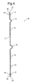
- Figure 4 is a cross section view of the roll formed panel;
- Figure 5 is a side view of the vehicle door module without hardware components; and
- Figure 6 is a schematic view of the roll forming process.
-
- Referring to Figure 1, a
vehicle door 10 is shown with aninner panel 8 and anouter panel 6. The hardware module is comprised of a roll formed panel (panel) 28 having afirst end 50, asecond end 52, a firstlongitudinal edge 20, a secondlongitudinal edge 24 and a longitudinal extendingcentral portion 26 including aninterior side 30 which faces the interior of the compartment of the vehicle. Thepanel 28 is mounted to theinner panel 8 of the vehicle door (door) 10 using mechanical fasteners. Thepanel 28 provides additional structure to give structural integrity to thedoor 10. Various hardware components are attached to thepanel 28. - Referring to Figure 2, the
interior side 30 of thepanel 28 is shown. Awiring harness 68, including a sealing grommet, is shown attached to thepanel 28. Aspeaker 70 and an insidedoor handle assembly 72 are shown attached to thepanel 28. Aninside handle cable 73 of the insidedoor handle assembly 72 is also shown and extends from theinside handle assembly 72 to theinterior side 30. A rearglass run channel 75 is also shown. - Referring to Figure 3, the
panel 28 has anexterior side 31 that faces the outer panel 6 (Figure 1). An outside handle andkey cylinder assembly 74 is mounted onto thepanel 28 for positioning on the outer panel 6 (Figure 1) when thedoor 10 is assembled. Amotor 76 is mounted on theexterior side 31 and provides the power to lift and lower the window glass. If themotor 76 were mounted on theinterior side 30, a housing would be required to keep the sector gear from riding off the pinion. However, themotor 76 and thesector gear 90 are mounted on theexterior side 31 and there is no need for a separate housing. - A
window regulator mechanism 78 is shown disposed in the vehicle. Thewindow regulator mechanism 78 is powered by themotor 76 and provides window adjustment and control and is shown disposed in thedoor 10. Thewindow regulator mechanism 78 can be any of a number of conventional systems but preferable is an X-arm type that can be mechanically fastened directly to thepanel 28. - The
window regulator mechanism 78 comprises alift arm 80 having afirst end 81 and an opposingsecond end 83, where thefirst end 81 is pivotally mounted to asector gear 90 and thesecond end 83 is slidably mounted to afirst channel member 82. Thesector gear 90 is driven by a pinion and provides the mechanism by which the window glass is lifted and lowered. As is known in the art, thefirst channel member 82 is intended to engage the windowpane and is typically mounted to a lower portion of the windowpane. A balancingarm 78 pivotally connects thelift arm 80 at a point that preferably comprises a midpoint of thelift arm 80. The balancingarm 78 has afirst end 92 and an opposingsecond end 94, where thefirst end 92 is slidably connected to asecond channel member 86 mounted onto the panel 28 (Figure 1). Thesecond end 94 of the balancingarm 78 is slidably mounted to thefirst channel member 82. - Referring to Figure 4, a cross section of the
panel 28 is shown without the attachment of any hardware components. The cross section of thepanel 28 is longitudinally uniform throughout. Thepanel 28 has multiplelongitudinal protrusions interior side 30.Longitudinal protrusions 32 are preferably semi-circular in shape and are formed proximate to firstlongitudinal edge 20 and the secondlongitudinal edge 24.Longitudinal protrusion 34 preferably is three-sided and is located proximate to thelongitudinal protrusion 32.Longitudinal protrusion 36 is preferably three-sided and is generally located along the center ofpanel 28. A longitudinal bend (bent portion) 40 is located proximate to thelongitudinal protrusion 32 located proximate to the secondlongitudinal edge 24. Thelongitudinal protrusions panel 28 increase the cross sectional moment of inertia of the panel and consequently, add structural rigidity and strength to the panel. - It is noted that the size, shape, location and number of the protrusions will vary with the space available within the
door 10 as well as the hardware components carried by thedoor 10. Avertical portion 38 located betweenprotrusion 36 andbend 40 is angled outward to accommodate attachment of thewindow regulator mechanism 78. The angle will vary depending on the type ofwindow regulator mechanism 78 employed as well as the size and shape of the door 10 (Figure 1). - Referring to Figures 1, 2 3 and 4, it is also desirable to provide separate "wet" and "dry" areas within the
door 10 to segregate the components that do not tolerate water vapor from those that do. For example, electrical controls for power windows and locks (not shown), thewiring harness 68, thespeaker 70, inside handleassembly 72 are located inside the vapor barrier thus preventing exposure to water vapor. - The
panel 28 is provided with an area adapted to contain the 'dry' components of the hardware. The preferred sealing method is a sealingmember 96, and most preferably, a sealing bead, although other suitable sealing means may be employed. Sealingbead 96, comprised of closed cell foam, is placed insidecavities 88 oflongitudinal protrusions 32 and continues along thefirst end 50 andsecond end 52 of thepanel 28. Thus, a continuous seal is formed around theperiphery 98 of thepanel 28 where it interfaces with theinner panel 8 of thedoor 10. The sealing bead creates a water vapor barrier that eliminates the need for a separate plastic or foam water barrier. The sealingmember 96 provides a dry area on theinterior side 30 of thepanel 28 that is free from exposure to water vapor. Advantageously, thepanel 28 functions simultaneously as the carrier of the various hardware components and the water vapor barrier. - Referring to Figures 2 and 5, the
interior side 30 of thepanel 28 havingfirst end 50 andsecond end 52 is shown without the attachment of any hardware components. A three-sided cutout 40 is located along the firstlongitudinal edge 20. Two four-sided apertures 42 are located proximate secondlongitudinal edge 24 and generally proximatefirst end 50 andsecond end 52. The trim panel hooks (not shown) are placed into thecutouts 40 andapertures 42 thus attaching the trim panel (not shown) to thedoor 10. Twoapertures 44 are located in thedoor 10 to attach to thechannel member 86 of thewindow regulator mechanism 78. Anaperture 46 is generally centrally located and accepts a stud or other similar fastening means in order to attach thewindow regulator mechanism 78 to thepanel 28.Apertures 48 receive attachment hardware for connecting themotor 76 to thepanel 28. - Referring to Figures 2 and 5, two
apertures 54 are located within thepanel 28. Oneaperture 54 is located proximate to thefirst end 50. Thesecond aperture 54 is located proximate to thesecond end 52.Apertures 54 are provided to allow thewiring harness 68 to pass between the interior side 30 (Figure 4) and the exterior side 31 (Figure 3). Anaperture 56 is located within thepanel 28 and positions thespeaker 70 within thepanel 28. Two four-sided slots 58 are located proximate the firstlongitudinal edge 20 and position the insidedoor handle assembly 72. Two four-sided slots 60 are located proximate to the firstlongitudinal edge 20 and receive mechanical fasteners to attach the trim panel (not shown) onto theinterior side 30 of thepanel 28. Anaperture 62 is located proximate the firstlongitudinal edge 20 and thesecond end 52 for insertion of theinside handle cable 73 for providing access to the outside handle andkey cylinder assembly 74. Fourapertures 64 are located proximate thesecond end 52 and position the rearglass run channel 75. Threeapertures 66 are located along the firstlongitudinal edge 20 and threeapertures 66 are located along the secondlongitudinal edge 24.Apertures 66 accept mechanical fasteners for attachment of thepanel 28 to the inner panel 8 (Figure 1) of the door 10 (Figure 1). - Thus, the
panel 28 is installed into the interior of thedoor 10 and fastened therein. Hardware components are attached to thepanel 28 in predeterminedlocations using slots cutout 40 andapertures apertures cutout 40 andslots longitudinal protrusions longitudinal bend 40,vertical portion 38,apertures slots cutout 40 located within the panel vary in size and placement depending on the type of door 10 (Figure 1) in which thepanel 28 is assembled as well as the hardware components used. - Referring to Figures 1, 4 and 6,
panel 28 is made using a continuous roll forming process. The manufacture ofpanel 28 for a vehicle door module by a roll forming process starts with a length offlat stock 102. Thisflat stock 102 can be of any material that can be roll formed that is suitable for adoor 10. For example, theflat stock 102 can be made of steel or steel alloys. Theflat stock 102 is provided in coils and can be cut to any convenient length after the roll forming process. Before or prior to the roll forming process, theflat stock 102 is punched in order to create theapertures cutout 40 andslots - The
panel 28 is produced by feeding the rolledstock 102 through a series ofrolls 104 to gradually change the shape of the metal as it passes through therolls 104. Thus, the desiredlongitudinal protrusions longitudinal bend 40 andvertical portion 38 are formed. The roll forming process is used to change the shape of the coiled metal stock into desired contours without altering the cross-sectional area. Thepanel 28 will have increased longitudinal strength as compared to a similar panel formed using a conventional steel stamping process. - Advantageously,
panel 28 is formed as a single integral unit at the mill from a continuous section of steel. Thus, the use of multiple dies and post-processing operations (e.g. machining) is eliminated thereby greatly decreasing the costs while increasing the ease of manufacturability. Thepanel 28 also provides additional structure to give integrity to the construction of thedoor 10. Roll forming is advantageous over steel stamping because production speed is greater than other production methods. Further, end-unit assembly cost is reduced without compromising quality as compared to conventional steel stampings.Panel 28 maintains the structural integrity and rigidity of prior art vehicle doors as it is fabricated using a rolled beam process. - The present invention thus reduces cost and increases ease of manufacturability by producing a panel for attaching door hardware by a roll forming process as opposed to a panel formed by a conventional steel stamping process. The
panel 28 also carries the hardware components associated with adoor 10 while simultaneously providing for a sealing bead. Thus, thepanel 28 acts as a water vapor barrier thereby protecting the interior passenger compartment while eliminating the need for a separately installed water barrier. Apanel 28 also reduces post-processing operations required on a panel produced by a stamping process. Manufacturing time to produce the panel is also much less than that of a stamped panel that is a multi-step process. Thus, cost to produce thepanel 28 is reduced. Therefore, thepanel 28 produces the lowest cost possible for a panel formed from a steel plate while providing increased strength of the door structure. Thepanel 28 also incorporates a wet-dry water management system integral with thepanel 28. - Referring to Figure 4, it should be noted that it is within the scope of this invention that
longitudinal protrusions door 10 depending on the hardware components to be installed onto thepanel 28. - While preferred embodiments have been shown and described, various modifications and substitutions may be made thereto without departing from the spirit and scope of the invention. Accordingly, it is to be understood that the present invention has been described by way of illustration only, and such illustrations and embodiments as have been disclosed herein are not to be construed as limiting to the claims.
Claims (19)
- A panel (28) for a vehicle door module, the panel (28) comprising:a body formed by a roll forming process, the body having an interior side (30) and an opposing exterior side (31), the body including a predetermined number of longitudinal protrusions (32, 34, 36) formed during the roll forming process, the predetermined number of longitudinal protrusions (32, 34, 36) extending inwardly from the interior side (30), the panel (28) being shaped for reception in and attachment to the vehicle door (10).
- The panel (28) as set forth in claim 1, wherein the body includes a first edge (20) and an opposing second edge (24), wherein a first arcuate longitudinal protrusion (32) is formed in the body, the first arcuate longitudinal protrusion (32) being formed proximate the first edge (20).
- The panel (28) as set forth in claim 2, wherein the body includes a second arcuate longitudinal protrusion (32) formed in the body, the second arcuate longitudinal protrusion (32) being formed proximate the second edge (24).
- The panel (28) as set forth in claim 3, wherein the body includes a first three-sided longitudinal protrusion (34), the first three-sided longitudinal protrusion (34) being formed between the first and second arcuate longitudinal protrusions (32, 32).
- The panel (28) as set forth in claim 3, wherein the body includes a second three-sided longitudinal protrusion (36), the second three-sided longitudinal protrusion (36) being formed between the first and second arcuate longitudinal protrusions (32, 32).
- The panel (28) as set forth in claim 5, wherein the body includes a bent portion (40) formed between the second three-sided longitudinal protrusion (36) and the second arcuate longitudinal protrusion (32).
- The panel (28) as set forth in claim 3, wherein the first and second arcuate longitudinal protrusions (32, 32) define recesses (88, 88) formed in the exterior side (31) of the body.
- The panel (28) as set forth in claim 7, further including:a sealing member (96) for partitioning the body into a first section (100) defined between the sealing member (96), the sealing member (96) being disposed within the recesses (88, 88) formed in the exterior side (31).
- The panel (28) as set forth in claim 8, wherein the first section (100) comprises a dry area which is free from exposure to water vapor.
- The panel (28) as set forth in claim 8, wherein the body includes a periphery (98), the sealing member (96) forming a continuous seal around the periphery (98) of the body.
- A method for forming a panel (28) for a vehicle door module, the method comprising:providing stock material (102); andpassing the stock material (102) between a series of rollers (104) to successively change the shape of the stock material (102) into a panel (28) having an interior side (30) and an opposing exterior side (31), the panel (28) including a predetermined number of longitudinal protrusions (32, 34, 36) formed during the roll forming process, the predetermined number of longitudinal protrusions (32, 34, 36) extending inwardly from the interior side (30), the panel (28) being shaped for reception in and attachment to the vehicle door (10).
- The method as set forth in claim 9, wherein the stock material (102) comprises coiled metal stock.
- The method as set forth in claim 11, wherein passing the stock material (102) comprises:forming a first arcuate longitudinal protrusion (32) in the panel body, the first arcuate longitudinal protrusion (32) being formed proximate a first edge (20) of the panel (28).
- The method as set forth in claim 11, wherein passing the stock material comprises:forming a second arcuate longitudinal protrusion (32) in the panel (28), the second arcuate longitudinal protrusion (32) being formed proximate a second edge (24) of the panel (28).
- The method as set forth in claim 14, wherein passing the stock material (102) comprises:forming a first three-sided longitudinal protrusion (34), the first three-sided longitudinal protrusion (34) being formed between the first and second arcuate longitudinal protrusions (32, 32).
- The method as set forth in claim 14, wherein passing the stock material (102) comprises:forming a second three-sided longitudinal protrusion (36), the second three-sided longitudinal protrusion (36) being formed between the first and second arcuate longitudinal protrusions (32, 32).
- The method as set forth in claim 14, wherein the first and second arcuate longitudinal protrusions (32, 32) define recesses (88, 88) formed in the exterior side (31) of the panel (28).
- The method as set forth in claim 11, further including:providing a sealing member (96) for partitioning the panel (28) into a first section (100) defined between the sealing member (96), the sealing member (96) being disposed within the recesses (88, 88) formed in the exterior side (31).
- The method as set forth in claim 18, wherein the first section (100) comprises a dry area which is free from exposure to water vapor.
Applications Claiming Priority (2)
| Application Number | Priority Date | Filing Date | Title |
|---|---|---|---|
| US644619 | 2000-08-23 | ||
| US09/644,619 US6564525B1 (en) | 2000-08-23 | 2000-08-23 | Roll formed hardware module |
Publications (1)
| Publication Number | Publication Date |
|---|---|
| EP1182069A1 true EP1182069A1 (en) | 2002-02-27 |
Family
ID=24585665
Family Applications (1)
| Application Number | Title | Priority Date | Filing Date |
|---|---|---|---|
| EP01202661A Withdrawn EP1182069A1 (en) | 2000-08-23 | 2001-07-11 | Roll formed hardware module |
Country Status (2)
| Country | Link |
|---|---|
| US (1) | US6564525B1 (en) |
| EP (1) | EP1182069A1 (en) |
Families Citing this family (4)
| Publication number | Priority date | Publication date | Assignee | Title |
|---|---|---|---|---|
| DE60216101T2 (en) * | 2002-09-27 | 2007-03-29 | Harman Becker Automotive Systems Gmbh | Sound system for a vehicle |
| DE112009001888T5 (en) * | 2008-07-31 | 2012-01-12 | Inteva Products, Llc | Cross arm module for vehicle door |
| KR101500353B1 (en) * | 2012-12-11 | 2015-03-09 | 현대자동차 주식회사 | Composite vehicle body and manufacturing method thereof and vehicle body structure using the same |
| DE102012025392B3 (en) * | 2012-12-24 | 2014-02-20 | Audi Ag | Covering device for a with a locking wedge module in a connection of a vehicle door with a side wall frame of a vehicle body causing releasable coupling bringable holding jaw module |
Citations (5)
| Publication number | Priority date | Publication date | Assignee | Title |
|---|---|---|---|---|
| US5536060A (en) * | 1995-02-17 | 1996-07-16 | General Motors Corporation | Reinforced vehicle door |
| US5640869A (en) * | 1994-12-07 | 1997-06-24 | Aisin Seiki Kabushiki Kaisha | Method for producing rolled structural shapes |
| US5743588A (en) * | 1994-06-23 | 1998-04-28 | Ford Global Technologies, Inc. | Metallic section as reinforcement of a motor vehicle door |
| US5813719A (en) * | 1997-09-25 | 1998-09-29 | Trim Trends, Inc. | Side intrusion beam assembly having compensating welds at brackets |
| US6016630A (en) * | 1995-07-26 | 2000-01-25 | Aisin Seiki Kabushiki Kaisha | Door frame and method for forming the same |
Family Cites Families (10)
| Publication number | Priority date | Publication date | Assignee | Title |
|---|---|---|---|---|
| US4766025A (en) * | 1986-09-25 | 1988-08-23 | Sheller Globe Corp. | Composite molded article and method of making same |
| US4923539A (en) * | 1988-09-16 | 1990-05-08 | Stanztechnik Gmbh R+S | Method and apparatus for manufacturing trim panels including several trim components |
| EP0361740A3 (en) * | 1988-09-27 | 1991-09-11 | Bridgestone Australia Limited | Vehicle inner panel |
| DE69027334T2 (en) * | 1990-12-06 | 1997-01-23 | Kasai Kogyo Kk | METHOD FOR PRODUCING MOTOR VEHICLE DOOR INTERIOR PANELING |
| JP2594345Y2 (en) * | 1991-02-27 | 1999-04-26 | 池田物産 株式会社 | Vehicle door trim |
| JPH0732384A (en) * | 1993-04-26 | 1995-02-03 | Atoma Internatl Inc | Method of manufacturing door panel having integrated bolster |
| US5626382A (en) * | 1995-04-03 | 1997-05-06 | Lear Corporation | Molded plastic panel having integrated, localized soft-touch aesthetic feature |
| US5924760A (en) * | 1996-11-29 | 1999-07-20 | General Motors Corporation | One-piece corrugated anti-intrusion barrier and method |
| US5962089A (en) * | 1997-01-31 | 1999-10-05 | Simco Automotive Trim, Inc. | Automotive trim panel and method of making same |
| US5932331A (en) * | 1998-10-08 | 1999-08-03 | Simco Automotive Trim, Inc. | Automotive trim panel having dual density foam support layer |
-
2000
- 2000-08-23 US US09/644,619 patent/US6564525B1/en not_active Expired - Fee Related
-
2001
- 2001-07-11 EP EP01202661A patent/EP1182069A1/en not_active Withdrawn
Patent Citations (5)
| Publication number | Priority date | Publication date | Assignee | Title |
|---|---|---|---|---|
| US5743588A (en) * | 1994-06-23 | 1998-04-28 | Ford Global Technologies, Inc. | Metallic section as reinforcement of a motor vehicle door |
| US5640869A (en) * | 1994-12-07 | 1997-06-24 | Aisin Seiki Kabushiki Kaisha | Method for producing rolled structural shapes |
| US5536060A (en) * | 1995-02-17 | 1996-07-16 | General Motors Corporation | Reinforced vehicle door |
| US6016630A (en) * | 1995-07-26 | 2000-01-25 | Aisin Seiki Kabushiki Kaisha | Door frame and method for forming the same |
| US5813719A (en) * | 1997-09-25 | 1998-09-29 | Trim Trends, Inc. | Side intrusion beam assembly having compensating welds at brackets |
Also Published As
| Publication number | Publication date |
|---|---|
| US6564525B1 (en) | 2003-05-20 |
Similar Documents
| Publication | Publication Date | Title |
|---|---|---|
| EP1305178B1 (en) | Ultra-lightweight thin sliding door for a vehicle | |
| US6205714B1 (en) | Modular vehicle door | |
| EP2021198B1 (en) | Inner panel for a door assembly having an integrated intrusion beam | |
| US7363750B2 (en) | Sliding vehicle door with a moveable window assembly | |
| US6135537A (en) | Reinforced vehicle door assembly | |
| US6615475B2 (en) | Method for making vehicle door | |
| EP1758748B1 (en) | Structural door module | |
| JP2009535255A (en) | Lightweight modular hinge door | |
| US6022066A (en) | Door extension for vehicle doors | |
| US6719355B2 (en) | Motor vehicle door with a passenger protection system | |
| US20190232765A1 (en) | Convertible skeleton door | |
| US20040195860A1 (en) | Door-frame for a vehicle door | |
| US20040084930A1 (en) | Trim hardware carrier | |
| US6564525B1 (en) | Roll formed hardware module | |
| US7681940B2 (en) | Rear door assembly for a motor vehicle | |
| CN113276798B (en) | Back row safety belt structure | |
| US5351400A (en) | Converting and reinforcing vehicles | |
| CN107539077A (en) | The inner support plate with multiaspect mounting interface for the hardware module of door assembly | |
| JPH06504966A (en) | Structural module for car doors | |
| EP0336636A2 (en) | Functional door cartridge and method of manufacturing thereof | |
| US6484448B2 (en) | Method of assembling a vehicle door module | |
| DE19821077A1 (en) | Car door suitable for production by non-ferrous metal technology | |
| CN212604423U (en) | Door sash reinforcing assembly, door inner panel assembly and vehicle | |
| JP2001030841A (en) | Ceiling integrated overhead console mounting structure | |
| DE102013210008A1 (en) | Vehicle door reinforcing carrier for use in door assembly of motor car, has variable cross-section extending in longitudinal direction of carrier with respect to vehicle, and circular cross-section formed in support bend |
Legal Events
| Date | Code | Title | Description |
|---|---|---|---|
| PUAI | Public reference made under article 153(3) epc to a published international application that has entered the european phase |
Free format text: ORIGINAL CODE: 0009012 |
|
| AK | Designated contracting states |
Kind code of ref document: A1 Designated state(s): AT BE CH CY DE DK ES FI FR GB GR IE IT LI LU MC NL PT SE TR Kind code of ref document: A1 Designated state(s): DE FR GB |
|
| AX | Request for extension of the european patent |
Free format text: AL;LT;LV;MK;RO;SI |
|
| 17P | Request for examination filed |
Effective date: 20020827 |
|
| AKX | Designation fees paid |
Free format text: DE FR GB |
|
| STAA | Information on the status of an ep patent application or granted ep patent |
Free format text: STATUS: THE APPLICATION IS DEEMED TO BE WITHDRAWN |
|
| 18D | Application deemed to be withdrawn |
Effective date: 20040203 |