EP1182059A2 - Bead core and pneumatic tire using the same - Google Patents
Bead core and pneumatic tire using the same Download PDFInfo
- Publication number
- EP1182059A2 EP1182059A2 EP01305707A EP01305707A EP1182059A2 EP 1182059 A2 EP1182059 A2 EP 1182059A2 EP 01305707 A EP01305707 A EP 01305707A EP 01305707 A EP01305707 A EP 01305707A EP 1182059 A2 EP1182059 A2 EP 1182059A2
- Authority
- EP
- European Patent Office
- Prior art keywords
- single cord
- bead core
- bead
- start end
- stage
- Prior art date
- Legal status (The legal status is an assumption and is not a legal conclusion. Google has not performed a legal analysis and makes no representation as to the accuracy of the status listed.)
- Granted
Links
Images



Classifications
-
- B—PERFORMING OPERATIONS; TRANSPORTING
- B60—VEHICLES IN GENERAL
- B60C—VEHICLE TYRES; TYRE INFLATION; TYRE CHANGING; CONNECTING VALVES TO INFLATABLE ELASTIC BODIES IN GENERAL; DEVICES OR ARRANGEMENTS RELATED TO TYRES
- B60C15/00—Tyre beads, e.g. ply turn-up or overlap
- B60C15/04—Bead cores
-
- B—PERFORMING OPERATIONS; TRANSPORTING
- B60—VEHICLES IN GENERAL
- B60C—VEHICLE TYRES; TYRE INFLATION; TYRE CHANGING; CONNECTING VALVES TO INFLATABLE ELASTIC BODIES IN GENERAL; DEVICES OR ARRANGEMENTS RELATED TO TYRES
- B60C15/00—Tyre beads, e.g. ply turn-up or overlap
- B60C15/04—Bead cores
- B60C2015/048—Polygonal cores characterised by the winding sequence
-
- Y—GENERAL TAGGING OF NEW TECHNOLOGICAL DEVELOPMENTS; GENERAL TAGGING OF CROSS-SECTIONAL TECHNOLOGIES SPANNING OVER SEVERAL SECTIONS OF THE IPC; TECHNICAL SUBJECTS COVERED BY FORMER USPC CROSS-REFERENCE ART COLLECTIONS [XRACs] AND DIGESTS
- Y10—TECHNICAL SUBJECTS COVERED BY FORMER USPC
- Y10T—TECHNICAL SUBJECTS COVERED BY FORMER US CLASSIFICATION
- Y10T152/00—Resilient tires and wheels
- Y10T152/10—Tires, resilient
- Y10T152/10495—Pneumatic tire or inner tube
- Y10T152/10819—Characterized by the structure of the bead portion of the tire
Definitions
- This invention relates to a bead core of so-called monostrand type and a pneumatic tire using the same.
- so-called monostrand type bead core is constructed by spirally winding a single cord and stacking such spiral windings to each other as plural stages, wherein the single cord is aligned in the plural stages at the cross section of the bead core.
- the number of free ends of the single cord becomes minimum (start end and terminal end), so that the resistance to bead burst is excellent.
- the start end of the single cord in the bead core locates in an axially outermost position of a radially innermost stage, so that the bead core is subjected to a restraint from only one side.
- the start end slips outward from the above position in the radial direction through an elastic restoring force of the cord itself and may spring up to a sidewall portion of a pneumatic tire according to circumstances.
- vulcanization is carried out at such a state to fix the start end to the above slipped position, there is a problem that the start end repeatedly press-contacts with a carcass ply during the running to damage the carcass ply.
- an object of the invention to provide a bead core capable of preventing the slipping of the start end in the winding of the single cord to easily maintain a normal aligning wound state and a pneumatic tire using the same.
- a winding start end of the single cord is shifted from an axially outermost or innermost position of a radially innermost first stage to a next position at least corresponding to only one of the single cord, and after the single cord is spirally wound from the first stage to a second stage and arrives on a position above the start end, it is wound on the axially outermost or innermost empty position of the radially innermost first stage.
- the start end of the single cord usually locates in an axially outermost or innermost position of a radially innermost stage as previously mentioned.
- the start end of the single cord is shifted from the axially outermost or innermost position to a next position at least corresponding to only one of the single cord to form an empty region in the axially outermost or innermost position.
- the single cord is placed on the empty region of the first stage and thereafter returned to a position above the empty region filled with the single cord and further the winding is continues toward a subsequent third stage.
- the start end is strongly restrained by sandwiching from both sides by the continuous single cord.
- the start end is not slipped from the given position nor sprung upward and hence the damaging of a carcass ply is prevented.
- the single cord is aligned in checkers in the bead core.
- a pneumatic tire comprising a pair of bead portion each including a bead core embedded therein, wherein said bead core is formed by spirally winding a single cord and stacking spiral windings to each other as plural stages in a radial direction in which a winding start end of the single cord is shifted from an axially outermost or innermost position of a radially innermost first stage to a next position at least corresponding to only one of the single cord, and after the single cord is spirally wound from the first stage to a second stage and arrives on a position above the start end, it is wound on the axially outermost or innermost empty position of the radially innermost first stage.
- FIG. 1 an embodiment of the bead core according to the invention.
- the bead core 11 shown in FIG. 1 is a bead core generally called as a monostrand-type bead core, which is constructed by spirally and continuously winding a single cord 13, a steel cord 14 coated with an insulation rubber 12 in the illustrated embodiment into a cylindrical form and stacking such spiral windings 15 of the cylindrical form to each other outward in a radial direction.
- a start end M of the single cord 13 locates in a radially innermost stage, i.e. a first spiral winding 15a.
- the start end M has hitherto been located in an axially outermost position (left end in FIG. 1) or an axially innermost position (right end in FIG. 1). In this case, however, if the start end M is subjected to an external force, it is slipped outward or inward from the above position in the axial direction and may spring up outward in the radial direction as previously mentioned.
- the start end M of the single cord 13 is shifted from the axially outermost or innermost position of the radially innermost stage to a neat position at least corresponding to only one of the single cord 13.
- the start end M is shifted inward from the axially outermost position by only one of the single cord 13 in the axial direction to render the axially outermost position into an empty region K.
- the single cord 13 is spirally wound inward from the start end M in the axial direction three turns to form a cylindrical spiral winding 15a of the first stage.
- the winding order of the single cord 13 is represented by symbols T-1, T-2, ⁇ T-11 in FIG. 1.
- the single cord 13 is spirally wound from a position above the axially innermost position of the first stage in a winding direction opposite to that of the first stage to form a cylindrical spiral winding 15b of a second stage.
- the single cord 13 is wound at the empty region K in the axially outermost position of the first stage (seventh turn T-7) and then the winding is carried out at the axially outermost position of the second stage (eighth turn T-8).
- the start end M of the single cord 13 is strongly restrained from both sides by sandwiching between second turn T-2 and seventh turn T-7 of the continuous single cord 13 and hence the winding of the single cord 13 is easily maintained at a normal aligning state and the slipping of the start end M from the given position is never caused even if the external force is applied to the start end M in the bead core 11.
- the single cord 13 is spirally wound from a position above the axially outermost position of the second stage in a winding direction opposite to that of the second stage three turns to form a cylindrical spiral winding 15c of a third stage.
- the single cords 13 are accurately overlapped with each other in the radial direction, so that the single cord 13 is aligned at a checkers state in the bead core 11. Moreover, the number of the stages is favorable to be a range of 2 to 6.
- the connected portion of the bead filler pair is cut by a cutter 22 to divide into two bead fillers 21 and at the same time the joined bead cores are separated into individual bead cores 11.
- the cutter 22 gives an external force to the single cord 13 constituting the bead core 11, particularly the single cords 13 located at a side adjacent to the cutter.
- the start end M as a free end of the single cord is shifted inward from the axially outermost position of the first stage only by one of the single cord, so that the external force applied to the start end M is fairly decreased.
- the start end M is strongly restrained between turns T-2 and T-7 of the single cord 13 from both sides, so that the start end M is never slipped out outward from the given position and does not spring up.
- the single cords 13 located at the radially outermost positions are never slipped out even if external force is applied because they continue to front and back windings of the single cord 13 in any stages.
- FIG. 3 a first embodiment of incorporating the above bead core 11 into a pneumatic tire 25 according to the invention.
- This tire 25 comprises a pair of bead portions 26 each containing the bead core 11 embedded therein, a pair of sidewall portions 27 extending outward from these bead portions 26 in substantially a radial direction, and a substantially cylindrical tread portion 28 connecting outer ends of the sidewall portions 27 in the radial direction.
- the sidewall portions 27 and the tread portion 28 are reinforced by a carcass 29 extending substantially in a toroidal form, and both widthwise end portions of the carcass 29 are wound around the bead cores 11 from an inside of the tire toward an outside thereof and moored thereto.
- the start end M locates at a bead heel side, while in the bead core 11 embedded in the bead portion 26b (axially right side in FIG. 3), the start end M locates at a bead toe side.
- the single cord 13 in the vicinity of the start end M intends to be slipped out by a dragging force directing outward from the carcass 29 in the radial direction (external force) during the vulcanization of the green tire.
- the bead core 11 is constructed as mentioned above, however, the start end M is restrained by the single cord 13 from both sides and also the single cord 13 located inward from the start end M in the axial direction continues to front and back windings of the single cord 13, so that the start end M is never slipped out and is easily maintained at the normal aligned state.
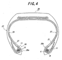
- FIG. 4 is a second embodiment of the pneumatic tire according to the invention.
- the start ends M in both the bead cores 11 are located so as to approach to each other, so that the start ends M of the bead cores 11 locate at the bead toe side in both the bead portions 26a, 26b.
- the slipping of the single cord 13 in the separation and cutting through the cutter 22 can be prevented in both the bead cores 11.
- FIG. 5 is a third embodiment of the pneumatic tire according to the invention.
- the start ends M of both the bead cores 11 are located so as to separate away from each other, so that the start ends M of the bead cores 11 in both the bead portions 26a, 26b locate at the bead heel side. In this case, the slipping of the single cord 13 during the vulcanization of the green tire can be prevented in both the bead cores 11.
- the shifting quantity of the start end M corresponds to only one of the single cord 13 in the above embodiments, it may be two or more of the single cord.
- the above embodiments are described with respect to the bead core 11 having substantially a rectangular form at section, the invention can be applied to a bead core having substantially a hexagonal form at section.
- the normal aligning state of the single cord in the bead core can easily be maintained by preventing the slipping of the start end of the single cord.
Landscapes
- Engineering & Computer Science (AREA)
- Mechanical Engineering (AREA)
- Tyre Moulding (AREA)
- Tires In General (AREA)
Abstract
Description
Claims (3)
- A bead core (11) formed by spirally winding a single cord (13) and stacking spiral windings (15) to each other as plural stages in a radial direction, characterized in that a winding start end (M) of the single cord (13) is shifted from an axially outermost or innermost position of a radially innermost first stage to a next position at least corresponding to only one of the single cord, and after the single cord is spirally wound from the first stage to a second stage and arrives at a position above the start end, it is wound on the axially outermost or innermost empty position of the radially innermost first stage.
- A bead core as claimed in claim 1, characterized in that the single cord (13) is aligned in a checkers pattern in the bead core (11).
- A pneumatic tire (25) having a pair of bead portions (26) each including a bead core (11) embedded therein, wherein said bead core is as claimed in claim 1 or 2.
Applications Claiming Priority (2)
| Application Number | Priority Date | Filing Date | Title |
|---|---|---|---|
| JP2000204992 | 2000-07-06 | ||
| JP2000204992A JP2002019428A (en) | 2000-07-06 | 2000-07-06 | Bead core and pneumatic tire provided with the bead core |
Publications (3)
| Publication Number | Publication Date |
|---|---|
| EP1182059A2 true EP1182059A2 (en) | 2002-02-27 |
| EP1182059A3 EP1182059A3 (en) | 2002-03-06 |
| EP1182059B1 EP1182059B1 (en) | 2005-02-02 |
Family
ID=18702157
Family Applications (1)
| Application Number | Title | Priority Date | Filing Date |
|---|---|---|---|
| EP01305707A Expired - Lifetime EP1182059B1 (en) | 2000-07-06 | 2001-07-02 | Bead core and pneumatic tire using the same |
Country Status (5)
| Country | Link |
|---|---|
| US (1) | US20020003018A1 (en) |
| EP (1) | EP1182059B1 (en) |
| JP (1) | JP2002019428A (en) |
| DE (1) | DE60108690T2 (en) |
| ES (1) | ES2236142T3 (en) |
Families Citing this family (4)
| Publication number | Priority date | Publication date | Assignee | Title |
|---|---|---|---|---|
| JP5636739B2 (en) * | 2010-05-26 | 2014-12-10 | 横浜ゴム株式会社 | Tire bead core and pneumatic tire |
| JP2011245997A (en) * | 2010-05-27 | 2011-12-08 | Yokohama Rubber Co Ltd:The | Pneumatic tire |
| JP2014198565A (en) * | 2014-07-29 | 2014-10-23 | 横浜ゴム株式会社 | Pneumatic tire |
| JP6804942B2 (en) * | 2016-11-14 | 2020-12-23 | Toyo Tire株式会社 | Pneumatic tires |
Family Cites Families (5)
| Publication number | Priority date | Publication date | Assignee | Title |
|---|---|---|---|---|
| US5141033A (en) * | 1987-12-08 | 1992-08-25 | National-Standard Company | Rubberless tire bead assemblies and methods of making same |
| JP3402503B2 (en) * | 1994-01-27 | 2003-05-06 | 株式会社ブリヂストン | Pneumatic tire |
| JPH07223412A (en) * | 1994-02-14 | 1995-08-22 | Sumitomo Rubber Ind Ltd | Bead core |
| IT1288728B1 (en) * | 1996-10-04 | 1998-09-24 | Bridgestone Firestone Tech | METALLIC HEEL FOR TIRES AND METHOD FOR ITS REALIZATION. |
| EP1541378A1 (en) * | 1998-11-26 | 2005-06-15 | Bridgestone Corporation | Pneumatic tire front wheel of motorcycle |
-
2000
- 2000-07-06 JP JP2000204992A patent/JP2002019428A/en not_active Withdrawn
-
2001
- 2001-07-02 EP EP01305707A patent/EP1182059B1/en not_active Expired - Lifetime
- 2001-07-02 DE DE60108690T patent/DE60108690T2/en not_active Expired - Fee Related
- 2001-07-02 ES ES01305707T patent/ES2236142T3/en not_active Expired - Lifetime
- 2001-07-05 US US09/898,077 patent/US20020003018A1/en not_active Abandoned
Also Published As
| Publication number | Publication date |
|---|---|
| DE60108690D1 (en) | 2005-03-10 |
| EP1182059A3 (en) | 2002-03-06 |
| JP2002019428A (en) | 2002-01-23 |
| EP1182059B1 (en) | 2005-02-02 |
| ES2236142T3 (en) | 2005-07-16 |
| US20020003018A1 (en) | 2002-01-10 |
| DE60108690T2 (en) | 2006-01-12 |
Similar Documents
| Publication | Publication Date | Title |
|---|---|---|
| JP3093812B2 (en) | Band layer molding method | |
| EP0595653A1 (en) | Pneumatic tyre | |
| JP2006062518A (en) | Heavy duty pneumatic tire and manufacturing method thereof | |
| EP1207060B1 (en) | Spiral hex bead and method of manufacture | |
| EP1342592A3 (en) | Motorcycle tire | |
| EP1182059B1 (en) | Bead core and pneumatic tire using the same | |
| JP3066319B2 (en) | Pneumatic tire | |
| EP1127717A3 (en) | Pneumatic tire | |
| JP2002059716A (en) | Pneumatic tire | |
| JP2010076570A (en) | Tire | |
| JP2001310604A (en) | Pneumatic radial tire | |
| JP4255262B2 (en) | Pneumatic tire | |
| JP4004034B2 (en) | Heavy duty pneumatic tire and method of assembling heavy duty pneumatic tire | |
| JP2005145082A (en) | Bead core for tire and pneumatic tire | |
| EP0707984B1 (en) | Pneumatic radial tyre and method of making the same | |
| JP3568340B2 (en) | Flat radial tires for light trucks | |
| GB2276357A (en) | Pneumatic tyre | |
| JPH05319035A (en) | Pneumatic radial tires for heavy loads | |
| JP2000016033A (en) | Bead core made of a single metal wire and pneumatic tire provided with the bead core in a bead portion | |
| JPH07223412A (en) | Bead core | |
| JP4449373B2 (en) | Pneumatic tire | |
| JP2005053251A (en) | Pneumatic tire | |
| JP6965686B2 (en) | Pneumatic tires | |
| JP2001287506A (en) | Pneumatic radial tire | |
| JP2007230400A (en) | Pneumatic tire |
Legal Events
| Date | Code | Title | Description |
|---|---|---|---|
| PUAI | Public reference made under article 153(3) epc to a published international application that has entered the european phase |
Free format text: ORIGINAL CODE: 0009012 |
|
| PUAL | Search report despatched |
Free format text: ORIGINAL CODE: 0009013 |
|
| AK | Designated contracting states |
Kind code of ref document: A2 Designated state(s): AT BE CH CY DE DK ES FI FR GB GR IE IT LI LU MC NL PT SE TR Kind code of ref document: A2 Designated state(s): DE ES FR GB IT |
|
| AX | Request for extension of the european patent |
Free format text: AL;LT;LV;MK;RO;SI |
|
| AK | Designated contracting states |
Kind code of ref document: A3 Designated state(s): AT BE CH CY DE DK ES FI FR GB GR IE IT LI LU MC NL PT SE TR |
|
| AX | Request for extension of the european patent |
Free format text: AL;LT;LV;MK;RO;SI |
|
| 17P | Request for examination filed |
Effective date: 20020409 |
|
| AKX | Designation fees paid |
Free format text: DE ES FR GB IT |
|
| GRAP | Despatch of communication of intention to grant a patent |
Free format text: ORIGINAL CODE: EPIDOSNIGR1 |
|
| GRAS | Grant fee paid |
Free format text: ORIGINAL CODE: EPIDOSNIGR3 |
|
| GRAA | (expected) grant |
Free format text: ORIGINAL CODE: 0009210 |
|
| AK | Designated contracting states |
Kind code of ref document: B1 Designated state(s): DE ES FR GB IT |
|
| REG | Reference to a national code |
Ref country code: GB Ref legal event code: FG4D |
|
| REG | Reference to a national code |
Ref country code: IE Ref legal event code: FG4D |
|
| REF | Corresponds to: |
Ref document number: 60108690 Country of ref document: DE Date of ref document: 20050310 Kind code of ref document: P |
|
| REG | Reference to a national code |
Ref country code: ES Ref legal event code: FG2A Ref document number: 2236142 Country of ref document: ES Kind code of ref document: T3 |
|
| PLBE | No opposition filed within time limit |
Free format text: ORIGINAL CODE: 0009261 |
|
| STAA | Information on the status of an ep patent application or granted ep patent |
Free format text: STATUS: NO OPPOSITION FILED WITHIN TIME LIMIT |
|
| 26N | No opposition filed |
Effective date: 20051103 |
|
| ET | Fr: translation filed | ||
| PGFP | Annual fee paid to national office [announced via postgrant information from national office to epo] |
Ref country code: GB Payment date: 20060628 Year of fee payment: 6 |
|
| PGFP | Annual fee paid to national office [announced via postgrant information from national office to epo] |
Ref country code: DE Payment date: 20060629 Year of fee payment: 6 |
|
| PGFP | Annual fee paid to national office [announced via postgrant information from national office to epo] |
Ref country code: FR Payment date: 20060719 Year of fee payment: 6 |
|
| PGFP | Annual fee paid to national office [announced via postgrant information from national office to epo] |
Ref country code: ES Payment date: 20060724 Year of fee payment: 6 |
|
| PGFP | Annual fee paid to national office [announced via postgrant information from national office to epo] |
Ref country code: IT Payment date: 20060731 Year of fee payment: 6 |
|
| GBPC | Gb: european patent ceased through non-payment of renewal fee |
Effective date: 20070702 |
|
| PG25 | Lapsed in a contracting state [announced via postgrant information from national office to epo] |
Ref country code: DE Free format text: LAPSE BECAUSE OF NON-PAYMENT OF DUE FEES Effective date: 20080201 |
|
| PG25 | Lapsed in a contracting state [announced via postgrant information from national office to epo] |
Ref country code: GB Free format text: LAPSE BECAUSE OF NON-PAYMENT OF DUE FEES Effective date: 20070702 |
|
| REG | Reference to a national code |
Ref country code: FR Ref legal event code: ST Effective date: 20080331 |
|
| PG25 | Lapsed in a contracting state [announced via postgrant information from national office to epo] |
Ref country code: FR Free format text: LAPSE BECAUSE OF NON-PAYMENT OF DUE FEES Effective date: 20070731 |
|
| REG | Reference to a national code |
Ref country code: ES Ref legal event code: FD2A Effective date: 20070703 |
|
| PG25 | Lapsed in a contracting state [announced via postgrant information from national office to epo] |
Ref country code: ES Free format text: LAPSE BECAUSE OF NON-PAYMENT OF DUE FEES Effective date: 20070703 |
|
| PG25 | Lapsed in a contracting state [announced via postgrant information from national office to epo] |
Ref country code: IT Free format text: LAPSE BECAUSE OF NON-PAYMENT OF DUE FEES Effective date: 20070702 |