EP1182057B1 - Wheel having rotating bodies - Google Patents
Wheel having rotating bodies Download PDFInfo
- Publication number
- EP1182057B1 EP1182057B1 EP01120076A EP01120076A EP1182057B1 EP 1182057 B1 EP1182057 B1 EP 1182057B1 EP 01120076 A EP01120076 A EP 01120076A EP 01120076 A EP01120076 A EP 01120076A EP 1182057 B1 EP1182057 B1 EP 1182057B1
- Authority
- EP
- European Patent Office
- Prior art keywords
- rotating body
- rotating bodies
- wheel
- tip
- rotating
- Prior art date
- Legal status (The legal status is an assumption and is not a legal conclusion. Google has not performed a legal analysis and makes no representation as to the accuracy of the status listed.)
- Expired - Lifetime
Links
- 238000004512 die casting Methods 0.000 claims description 8
- 229920003002 synthetic resin Polymers 0.000 claims description 7
- 239000000057 synthetic resin Substances 0.000 claims description 7
- 239000000463 material Substances 0.000 claims description 5
- 230000035515 penetration Effects 0.000 claims description 5
- 229920001971 elastomer Polymers 0.000 claims description 3
- 239000002184 metal Substances 0.000 claims description 3
- 239000005060 rubber Substances 0.000 claims description 3
- 239000013013 elastic material Substances 0.000 claims description 2
- 238000010276 construction Methods 0.000 description 4
- 230000002159 abnormal effect Effects 0.000 description 3
- 230000007547 defect Effects 0.000 description 3
- 239000000853 adhesive Substances 0.000 description 2
- 230000001070 adhesive effect Effects 0.000 description 2
- 238000001746 injection moulding Methods 0.000 description 2
- 229920002635 polyurethane Polymers 0.000 description 2
- 239000004814 polyurethane Substances 0.000 description 2
- 0 CC(CC*1)CC1C=CC Chemical compound CC(CC*1)CC1C=CC 0.000 description 1
- JOYRKODLDBILNP-UHFFFAOYSA-N Ethyl urethane Chemical compound CCOC(N)=O JOYRKODLDBILNP-UHFFFAOYSA-N 0.000 description 1
- 230000000712 assembly Effects 0.000 description 1
- 238000000429 assembly Methods 0.000 description 1
- 238000005266 casting Methods 0.000 description 1
- 230000015556 catabolic process Effects 0.000 description 1
- 230000000295 complement effect Effects 0.000 description 1
- 238000006731 degradation reaction Methods 0.000 description 1
- 238000011161 development Methods 0.000 description 1
- 230000018109 developmental process Effects 0.000 description 1
- 239000000428 dust Substances 0.000 description 1
- 238000000034 method Methods 0.000 description 1
- 238000005096 rolling process Methods 0.000 description 1
- 229920003051 synthetic elastomer Polymers 0.000 description 1
- 239000005061 synthetic rubber Substances 0.000 description 1
- XLYOFNOQVPJJNP-UHFFFAOYSA-N water Substances O XLYOFNOQVPJJNP-UHFFFAOYSA-N 0.000 description 1
Images


Classifications
-
- B—PERFORMING OPERATIONS; TRANSPORTING
- B60—VEHICLES IN GENERAL
- B60B—VEHICLE WHEELS; CASTORS; AXLES FOR WHEELS OR CASTORS; INCREASING WHEEL ADHESION
- B60B19/00—Wheels not otherwise provided for or having characteristics specified in one of the subgroups of this group
- B60B19/003—Multidirectional wheels
-
- A—HUMAN NECESSITIES
- A61—MEDICAL OR VETERINARY SCIENCE; HYGIENE
- A61G—TRANSPORT, PERSONAL CONVEYANCES, OR ACCOMMODATION SPECIALLY ADAPTED FOR PATIENTS OR DISABLED PERSONS; OPERATING TABLES OR CHAIRS; CHAIRS FOR DENTISTRY; FUNERAL DEVICES
- A61G5/00—Chairs or personal conveyances specially adapted for patients or disabled persons, e.g. wheelchairs
- A61G5/10—Parts, details or accessories
-
- A—HUMAN NECESSITIES
- A61—MEDICAL OR VETERINARY SCIENCE; HYGIENE
- A61G—TRANSPORT, PERSONAL CONVEYANCES, OR ACCOMMODATION SPECIALLY ADAPTED FOR PATIENTS OR DISABLED PERSONS; OPERATING TABLES OR CHAIRS; CHAIRS FOR DENTISTRY; FUNERAL DEVICES
- A61G5/00—Chairs or personal conveyances specially adapted for patients or disabled persons, e.g. wheelchairs
- A61G5/10—Parts, details or accessories
- A61G5/1051—Arrangements for steering
-
- B—PERFORMING OPERATIONS; TRANSPORTING
- B60—VEHICLES IN GENERAL
- B60B—VEHICLE WHEELS; CASTORS; AXLES FOR WHEELS OR CASTORS; INCREASING WHEEL ADHESION
- B60B2310/00—Manufacturing methods
- B60B2310/20—Shaping
- B60B2310/204—Shaping by moulding, e.g. injection moulding, i.e. casting of plastics material
-
- B—PERFORMING OPERATIONS; TRANSPORTING
- B60—VEHICLES IN GENERAL
- B60B—VEHICLE WHEELS; CASTORS; AXLES FOR WHEELS OR CASTORS; INCREASING WHEEL ADHESION
- B60B2310/00—Manufacturing methods
- B60B2310/20—Shaping
- B60B2310/206—Shaping by stamping
-
- B—PERFORMING OPERATIONS; TRANSPORTING
- B60—VEHICLES IN GENERAL
- B60B—VEHICLE WHEELS; CASTORS; AXLES FOR WHEELS OR CASTORS; INCREASING WHEEL ADHESION
- B60B2310/00—Manufacturing methods
- B60B2310/30—Manufacturing methods joining
- B60B2310/305—Manufacturing methods joining by screwing
-
- B—PERFORMING OPERATIONS; TRANSPORTING
- B60—VEHICLES IN GENERAL
- B60B—VEHICLE WHEELS; CASTORS; AXLES FOR WHEELS OR CASTORS; INCREASING WHEEL ADHESION
- B60B2310/00—Manufacturing methods
- B60B2310/30—Manufacturing methods joining
- B60B2310/318—Manufacturing methods joining by adhesive bonding, e.g. glueing
-
- B—PERFORMING OPERATIONS; TRANSPORTING
- B60—VEHICLES IN GENERAL
- B60B—VEHICLE WHEELS; CASTORS; AXLES FOR WHEELS OR CASTORS; INCREASING WHEEL ADHESION
- B60B2360/00—Materials; Physical forms thereof
- B60B2360/30—Synthetic materials
- B60B2360/32—Plastic compositions
- B60B2360/324—Comprising polyurethane
-
- B—PERFORMING OPERATIONS; TRANSPORTING
- B60—VEHICLES IN GENERAL
- B60B—VEHICLE WHEELS; CASTORS; AXLES FOR WHEELS OR CASTORS; INCREASING WHEEL ADHESION
- B60B2360/00—Materials; Physical forms thereof
- B60B2360/30—Synthetic materials
- B60B2360/34—Reinforced plastics
- B60B2360/348—Resins
-
- B—PERFORMING OPERATIONS; TRANSPORTING
- B60—VEHICLES IN GENERAL
- B60B—VEHICLE WHEELS; CASTORS; AXLES FOR WHEELS OR CASTORS; INCREASING WHEEL ADHESION
- B60B2360/00—Materials; Physical forms thereof
- B60B2360/50—Rubbers
-
- B—PERFORMING OPERATIONS; TRANSPORTING
- B60—VEHICLES IN GENERAL
- B60Y—INDEXING SCHEME RELATING TO ASPECTS CROSS-CUTTING VEHICLE TECHNOLOGY
- B60Y2200/00—Type of vehicle
- B60Y2200/80—Other vehicles not covered by groups B60Y2200/10 - B60Y2200/60
- B60Y2200/84—Wheelchairs
Definitions
- the present invention relates to a wheel having rotating bodies in which a plurality of non-turning type rotating bodies to be rotated in a direction orthogonal to the straight-forward direction of the wheel are disposed around the wheel for changing the advancing direction.
- the invention relates to a wheel according to the preamble of claim 1.
- Such a wheel is known from US-A- 5 246 238 .
- the wheel having the rotating bodies in which roller-like rotating bodies to be rotated in the direction orthogonal to the straight-forward direction are disposed on a rotary shaft along an outer circumferential circle of the wheel, and a buffer member is disposed between the rotating bodies is disclosed in JP-A- 11-227404 .
- the wheel having a large number of spindle-like rotating bodies disposed in an inclined manner to the straight-forward direction under the assumption that drive wheels are provided is disclosed in Japanese Examined Patent Application Publication No. 7-12829 or Japanese Patent Publication No. 10-500049 (by PCT Application).
- the wheel can be traveled in the transverse direction or diagonally while the wheel is rotated according to the vector component by the rotating bodies for shifting course without any turn different from a caster, i.e., without increasing the width of the wheel; however, a space is essentially generated between forward and rear ends of the adjacent rotating bodies with the width corresponding to the diameter of the rotating bodies.
- the buffer member is interposed in the space since stones or the like are caught therein; however, there leaves a room for improvement in that a frictional resistance with the rotating bodies is generated, and the rotating bodies cannot be rotated smoothly by the non-rotation.
- the wheel can be similarly traveled in the transverse direction or diagonally without any turn by the diagonal rotating bodies for shifting course; however, a space is generated between the adjacent circumferential surfaces of the rotating bodies, and if the diameter of the wheel is increased and the width in the longitudinal direction of each rotating body in the straight-forward direction is suitably increased considering the ride-over of a step, the transverse width of the wheel, i.e., the radius of turn of the wheel is naturally increased by the rotating bodies in the diagonal arrangement.
- roller skate wheels which are constructed for rolling in both the forward and lateral directions of the skate, wherein the wheels comprise a plurality of rollers which are mounted on a wheel hub.
- the wheel hub is formed with a plurality of radial arms, provided in a star-shaped configuration and having an integral cylindrical portion extending orthogonal to the arm and forming a sleeve bearing for receiving a roller shaft.
- a pair of roller parts is mounted in a mirror-symmetrical manner.
- a group of such pairs of roller parts is formed around the center axis of each wheel.
- Such identical wheels are then provided one behind the other on a corresponding mounting structure provided on the outer sole of a boot for roller skating.
- the document EP-A-0 768 076 discloses a motorized wheelchair which comprises four wheels driven by an electric motor and each including a plurality of rotatable rollers around the perimeter thereof.
- the respective rollers are arranged in parallel to each other, distributed around the circumference of the wheel, and inclined under an angle between the direction of the axis around which the roller rotates, and the direction of the wheel axis.
- each of the rollers has the shape of an ellipsoid.
- the document US-A-4 715 460 discloses an omnidirectional wheelchair base having upper and lower flexible base plates held in spaced-apart alignment by a pair of front supports and a rear support. Specific wheels are provided and mounted to such a support structure. In this conventional construction, the wheels are provided in a specific manner wherein the wheels have a star-shaped carrier with radially extending support arms receiving separate barrel-shaped roller assemblies coupled to a frame in each wheel.
- the document US-A-2 083 766 discloses a tire and rim construction with a specific configuration, where a core has a series of spiral dovetail recesses in its periphery, a resilient shell for the core having spiral dovetail portions fitting into recesses by a spiral movement, and means are provided for locking the shell on the core.
- a shell can be made of an extruded moulded material on the outer periphery of a rotating roller element.
- each rotating body rotating in a direction orthogonal to the straight-forward direction of the wheel is rotatably supported around the axis of rotation across the radial direction around an axle, and each rotating body is formed in a shape that the diameter of a tip portion thereof is smaller than the diameter of a base end portion, and an arc of an outer circumferential circle of the wheel is formed by the circumferential surface.
- the rotating bodies are rotatably supported on the axis of rotation across the radial direction, and the diameter is gradually reduced from the base end portion to the tip portion, or once increased, and then reduced to form an outer circumferential circle of the wheel by the circumferential surface.
- the turn in the advancing direction like a caster is unnecessary, the advancing direction of a vehicle can be freely changed diagonally or in the longitudinal direction, and the space between the rotating bodies can be small enough to prevent the interference of the space between the rotating bodies even when the diameter of the wheel is increased so that a step can be easily got over.
- each rotating body When the tip portion of each rotating body penetrates a recessed portion of the counter base end portion, the space between the rotating bodies can be further reduced.
- An outer circumferential portion of the base end portion formed as the recessed portion of each rotating body is formed as an annular lip which is elastic according to the material of the rotating body, and when an annular stepped portion to allow penetration of the lip of the adjacent rotating body is formed in the tip portion of each rotating body, degradation of the true circularity caused by the space between the rotating bodies, i.e., generation of rattling noises in the rotating mode is suppressed.
- each rotating body is of a half-spindle shape in which the diameter thereof is continuously reduced from the base end portion to the tip portion, the difference in diameter between the forward and rear ends is increased, and the rotating bodies are easily brought close to each other to reduce the space.
- Each rotating body comprises a core portion rotatably supported around the axis of rotation and an outer cylindrical portion which surrounds the core portion around the axis of rotation and is a die casting formed of an elastic material, and if protruding and recessed portions which are engaged with each other in a shape-complementary manner by changing the section in the direction of the axis of rotation in protruding and recessed shape are formed on an outer circumferential surface of the core portion and an inner circumferential surface of the outer cylindrical portion, the wall thickness thereof can be limited when they are manufactured of die castings of a synthetic resin or rubber, and as a result, generation of small internal defects specific to the castings can be prevented, and generation of abnormal noises in the traveling mode can be suppressed.
- the core portion and the outer cylindrical portion are formed of a synthetic resin such as a polyurethane, and engaging surfaces of the protruding and recessed portions are adhered to each other, an appropriate elasticity to suppress the vibration is realized to easily and reliably enable the engagement.
- the core portion is formed of a metal, generation of small internal defects in the die casting of the outer cylindrical portion can be avoided.
- a wheel having rotating bodies which are employed in front wheels of four wheels of a wheelchair according to the present invention will be described with reference to Figs. 1 and 2 .
- a wheel 9 has a diameter so that a step between a sidewalk and a roadway of a road can be easily got over, and a plurality of rotating bodies 10 of the same shape rotating in the direction orthogonal to a straight-ahead direction of the wheel 9 are disposed around a rim 2 having an axle 1 in a center.
- Each rotating body 10 is rotatably supported by a shaft 26 located on the same plane as that of the radial circle in the direction of the radius R1 around the axis O of the axle 1 and on the axis X1 of rotation deviated from the plane orthogonal thereto and diagonally thereacross at an angle of deviation.
- the diameter of each rotating body 10 is continuously reduced from a base end portion 11 to a tip portion 12 along the radius R1, and a circumferential surface 19 forms an arc thereof at the position of rotation to an outer circumferential circle C1 of the wheel 9, and as a result, each rotating body 10 is formed in a half-spindle shape.
- the circumferential surface 19 rotating along the outer circumferential circle C1 of the wheel partially penetrates one half of the outer circumferential side of a conical recessed portion 25 formed on the base end portion 11 of the rotating bodies 10 with the tip portions 12 thereof adjacent to each other and is brought close to the base end portions 11 of the adjacent rotating bodies 10 with a space 19a of preferably 1 mm to 5 mm.
- a base end portion of a bearing arm 20 is mounted on a circumferential surface of the rim 2, and penetrates into a space 27 between a circumferential wall 25a on the rim 2 side of a recessed portion 25 and the circumferential surface 19 on the rim 2 side, and further penetrates into a space between the tip portions 12 and successively bent in the direction orthogonal to the adjacent shaft 26.
- An end on the base end side of the shaft 26 is supported at the middle position 21 of the bearing arm 20, and an end on the tip side of the shaft 26 of the adjacent rotating body 10 is supported at the tip position 22.
- the action of the wheel 9 of this configuration employed in front wheels of the wheelchair will be described below.
- the rotating bodies 10 When the wheelchair is pushed in the straight-forward direction A of the wheel 9, the rotating bodies 10 are moved straight forward without rotation.
- the rotating bodies 10 can be driven in a reverse direction similarly.
- the entire circumferential surfaces 19 of the rotating bodies 10 can form a substantially continuous outer circumferential circle C1 of the wheel.
- the space between the forward and rear ends of the rotating bodies 10 is very small so that the rotating action thereof is not interfered with each other, and as a result, no stones are caught in the spaces and a smooth traveling is ensured.
- the rotating bodies 10 in contact with the ground are rotated, and the advancing direction of the wheelchair is changed to the transverse direction.
- the wheel 9 is rotated around the axle 1 according to the component of the vector of the advancing force decomposed in the orthogonal direction, and at the same time, the rotating bodies 10 are also rotated around the shaft 26, and the advancing direction of the wheelchair is changed into the diagonally forward direction or the diagonally reversing direction. This means that the wheelchair can be traveled in any direction without increasing the transverse width of the wheel 9 by the non-turn of the rotating bodies 10.
- the circumferential surface 19 of the rotating bodies 10 is continuous to the outer circumference of the wheel 9 having a sufficient diameter, and as a result, the wheelchair can easily ride over a step or the like on a road surface without any hooking. Since rear wheels of the wheelchair are provided with no rotating bodies 10, the wheelchair gradually changes the advancing direction in the transverse or diagonal traveling process, and is gradually moved into the straight-forward moving condition.
- the bearing arm 20 is hidden by the rotating bodies 10, and excellent in appearance, it can be supported by the ring-like bearing arm inserted in grooves formed in the circumferential surface of the rotating bodies 10. Further, the rotary shaft on the tip side or the adjacent recessed portion side of the rotating body can be successively and alternately supported in a cantilever manner at the tip position of the radially disposed bearing arms without supporting the rotary shaft on the recessed portion 25 side at the middle position of the bearing arms 20.
- Fig. 3 shows another supporting structure of the rotating body, in place of the above shaft 26, and a bearing bolt 33 ( Fig. 3B ) having a recessed curved surface 33a receiving a ball 32 is screwed in a base end portion 31 and a tip portion on the axis X1 of rotation of a rotating body 30 as shown in Fig. 3A .
- This recessed curved surface functions as a rotary recessed portion of the rotating body 30 to be rotatably engaged with the ball 32.
- a recessed curved surface 35a receiving the ball 32 is formed at the tip position and the middle position of the bearing arm 35 mounted on the rim 2 ( Fig. 3C ).
- the bearing arm 35 penetrates into a space between the tip portion of the rotating body 30 and the recessed portion of the adjacent rotating body 30, rotatably supports the rotary recessed portion on the tip side of the rotating body 30 at the tip position via the ball 32, and supports the rotary recessed portion on the recessed portion side of the base end portion 31 of the adjacent rotating body 30 at the middle position.
- No recessed portion is formed in the base end portion of the rotating body, and stones or the like are less easily caught by a reduced space between the rotating bodies adjacent to each other compared with simple cylindrical rotating bodies of uniform diameter even when the rotating body is rotatably supported in a cantilever manner by the bearing arm mounted on the rim.
- the base end portion of the rotating body is supported at the middle position in a similar manner to that of the above configuration, and the tip portion can be supported at the extended tip position by extending the bearing arm so that the rotating body is supported on both sides.
- Fig. 4 shows another embodiment of the rotating body to suppress the vibration in the traveling mode
- each rotating body 40 rotatably mounted on the shaft 26 supported by the bearing arm 20a is formed of a synthetic resin
- a recessed portion 45 to allow partial penetration of the adjacent rotating body 40 is formed in the base end portion
- a base end portion of the outer circumference is formed as an annular lip 41 which is elastic according to a material thereof.
- an annular stepped portion 42 to allow penetration of the lip 41 of the adjacent rotating body 40 is formed on the outer circumferential portion of the tip of each rotating body 40.
- a stepped surface 42a is reduced in inside diameter in proportion to the thickness of the lip 41, and the width in the longitudinal direction corresponds to a penetration of the lip 41.
- the tip of the lip 41 is brought close to a falling surface 42b to eliminate any space between adjacent portions, the true circularity of the wheel is ensured, the tip is restricted by the stepped surface 42a on the lip 41 in the traveling mode, and the deflection of the lip 41 is suppressed. As a result, rattling noise in the traveling mode can be eliminated, and the wheelchair can be moved smoothly, and the ride quality is improved.
- FIG. 5 shows still another embodiment when a rotating body is formed of a synthetic resin.
- a rotating body 50 comprising a core portion 51 with the shaft 26 passed therethrough and an outer cylindrical portion 52 to surround this core portion around the axis of rotation and from a base end side, is manufactured as a separate die casting by the injection molding of a polyurethane which generates no vibration as the wheel and is appropriately elastic.
- a plurality of stages of protruding and recessed portions 51a and 52a which are engaged with each other in a complementary manner in shape with the section in the direction of the axis of rotation changed in a protruding shape and a recessed shape are formed on an outer circumferential surface of the core portion 51 and an inner circumferential surface of the outer cylindrical portion 52.
- the outer cylindrical portion 52 is fitted to the core portion 51 making use of each elasticity, and an adhesive is applied to each engaging surface 55 of the protruding and recessed portions 51a and 52a to reliably join both portions with each other.
- the die casting is possibly formed of rubber, and the core portion is formed of a metal and pressed, and fitted to the outer cylindrical portion of die casting of a synthetic resin such as urethane or rubber, and in such a case, the wall thickness of the die casting is similarly reduced, and generation of small internal defects can be avoided.
- the wheel 9 can be employed in rear wheels of the wheelchair.
- the wheelchair can be freely traveled in any direction.
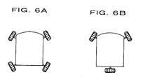
- front wheels are deflected inside forward each other, and rear wheels are defected inside backward each other as shown in Fig. 6A .
- Fig. 6B when employing the above wheel in a three-wheel drive vehicle, the configuration is shown in Fig. 6B , and the vehicle is driven only by front wheels in a straight-forward moving mode.
Landscapes
- Public Health (AREA)
- Health & Medical Sciences (AREA)
- Life Sciences & Earth Sciences (AREA)
- Animal Behavior & Ethology (AREA)
- General Health & Medical Sciences (AREA)
- Veterinary Medicine (AREA)
- Mechanical Engineering (AREA)
- Engineering & Computer Science (AREA)
- Tires In General (AREA)
- Handcart (AREA)
- Rolls And Other Rotary Bodies (AREA)
- Vehicle Body Suspensions (AREA)
- Rollers For Roller Conveyors For Transfer (AREA)
- Auxiliary Devices For And Details Of Packaging Control (AREA)
Abstract
Description
- The present invention relates to a wheel having rotating bodies in which a plurality of non-turning type rotating bodies to be rotated in a direction orthogonal to the straight-forward direction of the wheel are disposed around the wheel for changing the advancing direction. In particular, the invention relates to a wheel according to the preamble of
claim 1. Such a wheel is known fromUS-A- 5 246 238 . - Regarding the wheel having the rotating bodies, the wheel in which roller-like rotating bodies to be rotated in the direction orthogonal to the straight-forward direction are disposed on a rotary shaft along an outer circumferential circle of the wheel, and a buffer member is disposed between the rotating bodies is disclosed in
JP-A- 11-227404 7-12829 10-500049 - By using the former wheel, the wheel can be traveled in the transverse direction or diagonally while the wheel is rotated according to the vector component by the rotating bodies for shifting course without any turn different from a caster, i.e., without increasing the width of the wheel; however, a space is essentially generated between forward and rear ends of the adjacent rotating bodies with the width corresponding to the diameter of the rotating bodies. Thus, the buffer member is interposed in the space since stones or the like are caught therein; however, there leaves a room for improvement in that a frictional resistance with the rotating bodies is generated, and the rotating bodies cannot be rotated smoothly by the non-rotation.
- On the other hand, by using the latter wheel, the wheel can be similarly traveled in the transverse direction or diagonally without any turn by the diagonal rotating bodies for shifting course; however, a space is generated between the adjacent circumferential surfaces of the rotating bodies, and if the diameter of the wheel is increased and the width in the longitudinal direction of each rotating body in the straight-forward direction is suitably increased considering the ride-over of a step, the transverse width of the wheel, i.e., the radius of turn of the wheel is naturally increased by the rotating bodies in the diagonal arrangement.
- The document
US-A-5 246 238 discloses roller skate wheels which are constructed for rolling in both the forward and lateral directions of the skate, wherein the wheels comprise a plurality of rollers which are mounted on a wheel hub. In the conventional wheel, the wheel hub is formed with a plurality of radial arms, provided in a star-shaped configuration and having an integral cylindrical portion extending orthogonal to the arm and forming a sleeve bearing for receiving a roller shaft. - In the conventional roller skate wheel, on each of the roller shafts, a pair of roller parts is mounted in a mirror-symmetrical manner. A group of such pairs of roller parts is formed around the center axis of each wheel. Such identical wheels are then provided one behind the other on a corresponding mounting structure provided on the outer sole of a boot for roller skating.
- The document
EP-A-0 768 076 discloses a motorized wheelchair which comprises four wheels driven by an electric motor and each including a plurality of rotatable rollers around the perimeter thereof. In the conventional construction disclosed in this publication, the respective rollers are arranged in parallel to each other, distributed around the circumference of the wheel, and inclined under an angle between the direction of the axis around which the roller rotates, and the direction of the wheel axis. In the conventional construction, each of the rollers has the shape of an ellipsoid. - The document
US-A-4 715 460 discloses an omnidirectional wheelchair base having upper and lower flexible base plates held in spaced-apart alignment by a pair of front supports and a rear support. Specific wheels are provided and mounted to such a support structure. In this conventional construction, the wheels are provided in a specific manner wherein the wheels have a star-shaped carrier with radially extending support arms receiving separate barrel-shaped roller assemblies coupled to a frame in each wheel. - Furthermore, the document
US-A-2 083 766 discloses a tire and rim construction with a specific configuration, where a core has a series of spiral dovetail recesses in its periphery, a resilient shell for the core having spiral dovetail portions fitting into recesses by a spiral movement, and means are provided for locking the shell on the core. Such a shell can be made of an extruded moulded material on the outer periphery of a rotating roller element. - Accordingly, it is an object of the present invention to provide a wheel having rotating bodies which is provided with non-turning type rotating bodies to suppress generation of a space between the rotating bodies.
- The object is solved in a satisfying manner by a wheel as defined in
claim 1. Further developments thereof are indicated in the subclaims. - In the present invention, each rotating body rotating in a direction orthogonal to the straight-forward direction of the wheel is rotatably supported around the axis of rotation across the radial direction around an axle, and each rotating body is formed in a shape that the diameter of a tip portion thereof is smaller than the diameter of a base end portion, and an arc of an outer circumferential circle of the wheel is formed by the circumferential surface. The rotating bodies are rotatably supported on the axis of rotation across the radial direction, and the diameter is gradually reduced from the base end portion to the tip portion, or once increased, and then reduced to form an outer circumferential circle of the wheel by the circumferential surface.
- In accordance with the present invention, the turn in the advancing direction like a caster is unnecessary, the advancing direction of a vehicle can be freely changed diagonally or in the longitudinal direction, and the space between the rotating bodies can be small enough to prevent the interference of the space between the rotating bodies even when the diameter of the wheel is increased so that a step can be easily got over.
- When the tip portion of each rotating body penetrates a recessed portion of the counter base end portion, the space between the rotating bodies can be further reduced. An outer circumferential portion of the base end portion formed as the recessed portion of each rotating body is formed as an annular lip which is elastic according to the material of the rotating body, and when an annular stepped portion to allow penetration of the lip of the adjacent rotating body is formed in the tip portion of each rotating body, degradation of the true circularity caused by the space between the rotating bodies, i.e., generation of rattling noises in the rotating mode is suppressed.
- If each rotating body is of a half-spindle shape in which the diameter thereof is continuously reduced from the base end portion to the tip portion, the difference in diameter between the forward and rear ends is increased, and the rotating bodies are easily brought close to each other to reduce the space.
- Each rotating body comprises a core portion rotatably supported around the axis of rotation and an outer cylindrical portion which surrounds the core portion around the axis of rotation and is a die casting formed of an elastic material, and if protruding and recessed portions which are engaged with each other in a shape-complementary manner by changing the section in the direction of the axis of rotation in protruding and recessed shape are formed on an outer circumferential surface of the core portion and an inner circumferential surface of the outer cylindrical portion, the wall thickness thereof can be limited when they are manufactured of die castings of a synthetic resin or rubber, and as a result, generation of small internal defects specific to the castings can be prevented, and generation of abnormal noises in the traveling mode can be suppressed. In this state, if the core portion and the outer cylindrical portion are formed of a synthetic resin such as a polyurethane, and engaging surfaces of the protruding and recessed portions are adhered to each other, an appropriate elasticity to suppress the vibration is realized to easily and reliably enable the engagement. When the core portion is formed of a metal, generation of small internal defects in the die casting of the outer cylindrical portion can be avoided.
- When a bearing arm with the base end portion mounted on the rim penetrates into a space between the tip portion of the rotating body and the recessed portion of the adjacent rotating body, the rotating bodies adjacent to each other with a small space therebetween can be rotatably supported with an excellent appearance and a simple structure using the arm.
-
-
Fig. 1 is a cross-sectional view of a major portion of a wheel having rotating bodies according to an embodiment of the present.invention; -
Fig. 2 is a perspective view of the wheel having the rotating body; -
Fig. 3 is a schematic representation of a support structure according to another embodiment of the rotating body; -
Fig. 4 is a cross-sectional view of the rotating body according to another embodiment; and -
Fig. 5 is a cross-sectional view of the rotating body according to still another embodiment. -
Fig. 6 is a plan view showing the wheel configuration in which the wheel having rotating bodies shown inFig. 1 is employed in an automatic traveling vehicle. - A wheel having rotating bodies which are employed in front wheels of four wheels of a wheelchair according to the present invention will be described with reference to
Figs. 1 and 2 . Awheel 9 has a diameter so that a step between a sidewalk and a roadway of a road can be easily got over, and a plurality ofrotating bodies 10 of the same shape rotating in the direction orthogonal to a straight-ahead direction of thewheel 9 are disposed around arim 2 having anaxle 1 in a center. - Each
rotating body 10 is rotatably supported by ashaft 26 located on the same plane as that of the radial circle in the direction of the radius R1 around the axis O of theaxle 1 and on the axis X1 of rotation deviated from the plane orthogonal thereto and diagonally thereacross at an angle of deviation. The diameter of each rotatingbody 10 is continuously reduced from abase end portion 11 to atip portion 12 along the radius R1, and acircumferential surface 19 forms an arc thereof at the position of rotation to an outer circumferential circle C1 of thewheel 9, and as a result, eachrotating body 10 is formed in a half-spindle shape. - The
circumferential surface 19 rotating along the outer circumferential circle C1 of the wheel partially penetrates one half of the outer circumferential side of a conical recessedportion 25 formed on thebase end portion 11 of therotating bodies 10 with thetip portions 12 thereof adjacent to each other and is brought close to thebase end portions 11 of the adjacentrotating bodies 10 with aspace 19a of preferably 1 mm to 5 mm. - In addition, a base end portion of a
bearing arm 20 is mounted on a circumferential surface of therim 2, and penetrates into aspace 27 between a circumferential wall 25a on therim 2 side of arecessed portion 25 and thecircumferential surface 19 on therim 2 side, and further penetrates into a space between thetip portions 12 and successively bent in the direction orthogonal to theadjacent shaft 26. An end on the base end side of theshaft 26 is supported at themiddle position 21 of thebearing arm 20, and an end on the tip side of theshaft 26 of the adjacent rotatingbody 10 is supported at thetip position 22. - The action of the
wheel 9 of this configuration employed in front wheels of the wheelchair will be described below. When the wheelchair is pushed in the straight-forward direction A of thewheel 9, therotating bodies 10 are moved straight forward without rotation. Therotating bodies 10 can be driven in a reverse direction similarly. The entirecircumferential surfaces 19 of therotating bodies 10 can form a substantially continuous outer circumferential circle C1 of the wheel. The space between the forward and rear ends of therotating bodies 10 is very small so that the rotating action thereof is not interfered with each other, and as a result, no stones are caught in the spaces and a smooth traveling is ensured. - When the wheelchair is pushed in the transverse direction, the
rotating bodies 10 in contact with the ground are rotated, and the advancing direction of the wheelchair is changed to the transverse direction. When the wheelchair is pushed diagonally, thewheel 9 is rotated around theaxle 1 according to the component of the vector of the advancing force decomposed in the orthogonal direction, and at the same time, therotating bodies 10 are also rotated around theshaft 26, and the advancing direction of the wheelchair is changed into the diagonally forward direction or the diagonally reversing direction. This means that the wheelchair can be traveled in any direction without increasing the transverse width of thewheel 9 by the non-turn of therotating bodies 10. Thecircumferential surface 19 of therotating bodies 10 is continuous to the outer circumference of thewheel 9 having a sufficient diameter, and as a result, the wheelchair can easily ride over a step or the like on a road surface without any hooking. Since rear wheels of the wheelchair are provided with norotating bodies 10, the wheelchair gradually changes the advancing direction in the transverse or diagonal traveling process, and is gradually moved into the straight-forward moving condition. - In the above embodiment, the
bearing arm 20 is hidden by therotating bodies 10, and excellent in appearance, it can be supported by the ring-like bearing arm inserted in grooves formed in the circumferential surface of therotating bodies 10. Further, the rotary shaft on the tip side or the adjacent recessed portion side of the rotating body can be successively and alternately supported in a cantilever manner at the tip position of the radially disposed bearing arms without supporting the rotary shaft on the recessedportion 25 side at the middle position of the bearingarms 20. -
Fig. 3 shows another supporting structure of the rotating body, in place of theabove shaft 26, and a bearing bolt 33 (Fig. 3B ) having a recessedcurved surface 33a receiving aball 32 is screwed in abase end portion 31 and a tip portion on the axis X1 of rotation of arotating body 30 as shown inFig. 3A . This recessed curved surface functions as a rotary recessed portion of therotating body 30 to be rotatably engaged with theball 32. On the other hand, a recessedcurved surface 35a receiving theball 32 is formed at the tip position and the middle position of thebearing arm 35 mounted on the rim 2 (Fig. 3C ). Thebearing arm 35 penetrates into a space between the tip portion of therotating body 30 and the recessed portion of the adjacentrotating body 30, rotatably supports the rotary recessed portion on the tip side of therotating body 30 at the tip position via theball 32, and supports the rotary recessed portion on the recessed portion side of thebase end portion 31 of the adjacentrotating body 30 at the middle position. - No recessed portion is formed in the base end portion of the rotating body, and stones or the like are less easily caught by a reduced space between the rotating bodies adjacent to each other compared with simple cylindrical rotating bodies of uniform diameter even when the rotating body is rotatably supported in a cantilever manner by the bearing arm mounted on the rim. In such a case, the base end portion of the rotating body is supported at the middle position in a similar manner to that of the above configuration, and the tip portion can be supported at the extended tip position by extending the bearing arm so that the rotating body is supported on both sides.
-
Fig. 4 shows another embodiment of the rotating body to suppress the vibration in the traveling mode, and similar to the aboverotating body 10, each rotatingbody 40 rotatably mounted on theshaft 26 supported by thebearing arm 20a is formed of a synthetic resin, a recessedportion 45 to allow partial penetration of the adjacentrotating body 40 is formed in the base end portion, and a base end portion of the outer circumference is formed as anannular lip 41 which is elastic according to a material thereof. On the other hand, an annular steppedportion 42 to allow penetration of thelip 41 of the adjacentrotating body 40 is formed on the outer circumferential portion of the tip of eachrotating body 40. A steppedsurface 42a is reduced in inside diameter in proportion to the thickness of thelip 41, and the width in the longitudinal direction corresponds to a penetration of thelip 41. - The tip of the
lip 41 is brought close to a fallingsurface 42b to eliminate any space between adjacent portions, the true circularity of the wheel is ensured, the tip is restricted by the steppedsurface 42a on thelip 41 in the traveling mode, and the deflection of thelip 41 is suppressed. As a result, rattling noise in the traveling mode can be eliminated, and the wheelchair can be moved smoothly, and the ride quality is improved. -
Fig. 5 shows still another embodiment when a rotating body is formed of a synthetic resin. A rotatingbody 50 comprising acore portion 51 with theshaft 26 passed therethrough and an outercylindrical portion 52 to surround this core portion around the axis of rotation and from a base end side, is manufactured as a separate die casting by the injection molding of a polyurethane which generates no vibration as the wheel and is appropriately elastic. A plurality of stages of protruding and recessedportions core portion 51 and an inner circumferential surface of the outercylindrical portion 52. The outercylindrical portion 52 is fitted to thecore portion 51 making use of each elasticity, and an adhesive is applied to each engagingsurface 55 of the protruding and recessedportions - Generation of abnormal noises in the traveling mode attributable to loose material, blowholes, shrinkage cavity, etc. which can be generated in implementing the integratedly injection molding of the thick-walled rotating body can be avoided. In addition, the dust or water is prevented from entering between the protruding and recessed
portions - In joining these protruding and recessed portions, it is confirmed that a highly reliable adhesion can be realized by bonding the engaging
surfaces 55 to each other using a known adhesive which is heated when components thereof are mixed with each other. The die casting is possibly formed of rubber, and the core portion is formed of a metal and pressed, and fitted to the outer cylindrical portion of die casting of a synthetic resin such as urethane or rubber, and in such a case, the wall thickness of the die casting is similarly reduced, and generation of small internal defects can be avoided. - In the above embodiments, the
wheel 9 can be employed in rear wheels of the wheelchair. In addition, by providing the rotating bodies on all three or four wheels, the wheelchair can be freely traveled in any direction. When employing the above wheel in every wheel of a four-wheel drive vehicle, front wheels are deflected inside forward each other, and rear wheels are defected inside backward each other as shown inFig. 6A . Similarly, when employing the above wheel in a three-wheel drive vehicle, the configuration is shown inFig. 6B , and the vehicle is driven only by front wheels in a straight-forward moving mode.
Claims (10)
- A wheel having rotating bodies with a plurality of rotating bodies (10, 30, 40, 50) rotating in a direction orthogonal to the straight-forward direction of the wheel (9) disposed around the wheel (9), wherein each of the rotating bodies (10, 30, 40, 50) is rotatably supported around the axis of rotation (X1) across the radial direction around an axle (1),
wherein each of the rotating bodies (10, 30, 40, 50) is formed in a shape forming an arc of an outer circumferential circle (C1) of the wheel (9) by a circumferential surface (19),
wherein the diameter of a tip portion (12) is smaller than the diameter of a base end portion (11, 31) thereof,
characterized in that the tip portion (12) of each of the rotating bodies (10, 30, 40, 50) partially penetrates a recessed portion (25, 45) formed in the base end portion (11, 31) of the respective adjacent rotating body (10, 30, 40, 50) so that the tip portion (12) of each rotating body (10, 30, 40, 50) is brought close to the base end portion (11,31) of the adjacent rotating body (10, 30, 40, 50). - The wheel according to claim 1,
wherein an outer circumferential portion of the base end portion formed as a recessed portion (45) of each rotating body (40) is formed as an annular lip (41) which is elastic according to a material of the rotating body (40),
and wherein an annular stepped portion (42a) is formed on the tip portion of each of the rotating bodies (40) to allow penetration of the lip (41) of the adjacent rotating body (40). - The wheel according to claim 1or 2,
wherein each rotating body (10, 30, 40, 50) is of a half-spindle shape in which the diameter thereof is continuously reduced from the base end portion (11,31) to the tip portion (12). - The wheel according to any of claims 1 to 3, comprising:- a core portion (51) rotatably supported around the axis of rotation; and- an outer cylindrical portion (52) which surrounds the core portion (51) around the axis of rotation and is a die casting formed of an elastic material;- wherein protruding and recessed portions (51a, 52a), which are engaged with each other in a shape-complementary manner by changing the section in the direction of the axis of rotation in protruding and recessed shapes, are formed on an outer circumferential surface of the core portion (51) and an inner circumferential surface of the outer cylindrical portion (52).
- The wheel according to claim 4,
wherein the core portion (51) and the outer cylindrical portion (52) are formed of a synthetic resin, and engaging surfaces of the protruding and recessed portions (51a,52a) are adhered to each other. - The wheel according to claim 4,
wherein the core portion (51) is formed of a metal, and the outer cylindrical portion (52) is formed of a synthetic resin or a rubber. - The wheel according to any of claims 1 to 6,
wherein a bearing arm (20, 20a) with the base end portion mounted on a rim (2) penetrates into a space between the tip portion (12) of the rotating body (10, 40, 50) and the recessed portion of the adjacent rotating body (10, 40, 50),
wherein a shaft (26) on the tip side of the rotating bodies (10, 40, 50) is supported at the tip position of the bearing arm (20, 20a), and
wherein the shaft (26) on the recessed portion side of the rotating bodies (10, 40, 50) adjacent to each other is supported at the middle position of the bearing arm (20, 20a). - The wheel according to any of claims 1 to 6,
wherein a bearing arm with the base end portion mounted on a rim (2) penetrates into a space between the tip portion (12) of the rotating body (10, 30, 40, 50) and the recessed portion (25, 45) of the adjacent rotating body (10, 30, 40, 50),
and wherein a shaft on the tip side of the rotating bodies (10, 30, 40, 50), or a shaft on the recessed portion side of the rotating bodies (10, 30, 40, 50) adjacent to each other is supported at the tip position of the bearing arm. - The wheel according to any of claims 1 to 6,
wherein a bearing arm (35) with the base end portion mounted on a rim (2) penetrates into a space between the tip portion of the rotating body (30) and the recessed portion of the adjacent rotating body (30),
wherein a rotary recessed portion (33a) on the tip side of the rotating bodies (30) is supported on the tip position of the bearing arm (35), and
wherein the rotary recessed portion (33a) on the recessed portion side of the rotating bodies (30) adjacent to each other is supported at the middle position of the bearing arm (35). - The wheel according to any of claims 1 to 6,
wherein a bearing arm with the base end portion mounted on a rim (2) penetrates into a space between the tip portion of the rotating body (10, 30, 40, 50) and the recessed portion (25, 45) of the adjacent rotating body (10, 30, 40, 50),
and wherein a rotary recessed portion (33a) on the tip side of the rotating bodies (10, 30, 40, 50) or a rotary recessed portion (33a) on the recessed portion side of the rotating bodies (10, 30, 40, 50) adjacent to each other is supported at the tip position of the bearing arm.
Applications Claiming Priority (4)
| Application Number | Priority Date | Filing Date | Title |
|---|---|---|---|
| JP2000250857 | 2000-08-22 | ||
| JP2000250857 | 2000-08-22 | ||
| JP2001222548A JP3682248B2 (en) | 2000-08-22 | 2001-07-24 | Wheel with rotating body |
| JP2001222548 | 2001-07-24 |
Publications (3)
| Publication Number | Publication Date |
|---|---|
| EP1182057A2 EP1182057A2 (en) | 2002-02-27 |
| EP1182057A3 EP1182057A3 (en) | 2005-12-07 |
| EP1182057B1 true EP1182057B1 (en) | 2008-10-15 |
Family
ID=26598226
Family Applications (1)
| Application Number | Title | Priority Date | Filing Date |
|---|---|---|---|
| EP01120076A Expired - Lifetime EP1182057B1 (en) | 2000-08-22 | 2001-08-21 | Wheel having rotating bodies |
Country Status (5)
| Country | Link |
|---|---|
| US (1) | US6547339B2 (en) |
| EP (1) | EP1182057B1 (en) |
| JP (1) | JP3682248B2 (en) |
| AT (1) | ATE411189T1 (en) |
| DE (1) | DE60136139D1 (en) |
Families Citing this family (26)
| Publication number | Priority date | Publication date | Assignee | Title |
|---|---|---|---|---|
| JP4307153B2 (en) * | 2003-05-21 | 2009-08-05 | 関東自動車工業株式会社 | 4 wheel drive electric wheelchair |
| US6966807B2 (en) | 2003-11-12 | 2005-11-22 | Mattel, Inc. | Screw drive vehicle |
| USD518116S1 (en) | 2004-07-02 | 2006-03-28 | Mattel, Inc. | Screw drive toy vehicle |
| JP4208090B2 (en) | 2006-07-05 | 2009-01-14 | 関東自動車工業株式会社 | Differential steering electric car |
| RU2421341C2 (en) * | 2006-12-12 | 2011-06-20 | Юлия Алексеевна Щепочкина | Wheel |
| JP2009112533A (en) * | 2007-11-06 | 2009-05-28 | Kanto Auto Works Ltd | Wheelchair |
| JP4904600B2 (en) * | 2008-12-18 | 2012-03-28 | 関東自動車工業株式会社 | Wheel with rotating body and omnidirectional vehicle equipped with the same |
| US7641288B1 (en) | 2008-12-22 | 2010-01-05 | Baker Andrew R | Omni-directional wheel design for construction cost reduction |
| GB2468697A (en) * | 2009-03-18 | 2010-09-22 | James Martin | A turning device |
| JP5235184B2 (en) * | 2009-09-18 | 2013-07-10 | 本田技研工業株式会社 | Roller assembly |
| JP5235183B2 (en) * | 2009-09-18 | 2013-07-10 | 本田技研工業株式会社 | Roller assembly and assembly method thereof |
| US20110146736A1 (en) * | 2009-12-22 | 2011-06-23 | Pfafflin Ellen S | Walker |
| JP5083699B2 (en) * | 2010-03-05 | 2012-11-28 | トヨタ自動車東日本株式会社 | Fully driven wheel with rotating body |
| JP4978873B2 (en) * | 2010-03-05 | 2012-07-18 | 関東自動車工業株式会社 | Fully driven wheel with rotating body and inverted control unicycle |
| JP5083700B2 (en) * | 2010-03-10 | 2012-11-28 | トヨタ自動車東日本株式会社 | Fully driven wheel with rotating body |
| JP5282749B2 (en) * | 2010-03-10 | 2013-09-04 | トヨタ自動車東日本株式会社 | Fully driven wheel with rotating body |
| US9139040B2 (en) * | 2011-04-05 | 2015-09-22 | Jules Scogna | Omni-directional wheel assembly |
| JP5927031B2 (en) * | 2011-11-26 | 2016-05-25 | 本田技研工業株式会社 | Inverted pendulum type vehicle |
| CN102815164A (en) * | 2012-06-19 | 2012-12-12 | 杭州电子科技大学 | Novel omnidirectional wheel structure |
| JP5778740B2 (en) | 2013-10-29 | 2015-09-16 | Whill株式会社 | Omnidirectional moving wheel and omnidirectional moving vehicle equipped with the same |
| JP5687325B1 (en) | 2013-11-08 | 2015-03-18 | Whill株式会社 | Omnidirectional moving wheel and omnidirectional moving vehicle equipped with the same |
| JP6661304B2 (en) * | 2015-08-27 | 2020-03-11 | 株式会社土佐電子 | Omnidirectional vehicle wheels |
| CN105730142A (en) * | 2016-02-01 | 2016-07-06 | 吉林大学 | Bionic metal flexible rover wheel |
| CN212797182U (en) | 2017-04-12 | 2021-03-26 | Whill株式会社 | Electric Mobility Vehicles and Wheelchair Front Wheels |
| CN111251781B (en) * | 2018-11-19 | 2025-04-25 | 椅夫健康(厦门)智能科技有限公司 | A welded shaft for a universal wheel, a wheel assembly thereof, and a universal wheel |
| CN109760472B (en) * | 2019-03-27 | 2024-01-26 | 千巡科技(深圳)有限公司 | Omnidirectional wheel with multi-terrain adaptability |
Family Cites Families (12)
| Publication number | Priority date | Publication date | Assignee | Title |
|---|---|---|---|---|
| US1089020A (en) * | 1914-03-03 | Clark Allen Swinehart | Vehicle-tire. | |
| US1687330A (en) * | 1922-05-10 | 1928-10-09 | Goodrich Co B F | Resilient vehicle tire |
| US1690240A (en) * | 1925-08-26 | 1928-11-06 | Dunlop Tire And Ruber Corp Of | Method of manufacturing tires |
| US2083766A (en) * | 1935-07-01 | 1937-06-15 | Edwin E Wittkopp | Tire and rim construction |
| US4715460A (en) * | 1984-11-20 | 1987-12-29 | International Texas Industries, Inc. | Omnidirectional vehicle base |
| US5246238A (en) * | 1992-06-30 | 1993-09-21 | Brown Nathaniel R | Roller skate wheel |
| JP3112219B2 (en) | 1993-06-25 | 2000-11-27 | 富士ゼロックス株式会社 | Movement detection method and detector |
| CN2203140Y (en) | 1994-06-11 | 1995-07-12 | 福建实达电脑股份有限公司 | Computerized universal walking wheelchair |
| US6036278A (en) * | 1994-11-29 | 2000-03-14 | Glenn Boyer Technologies, Inc. | Multi durometer wheel for in-line skates |
| US5733015A (en) * | 1995-12-04 | 1998-03-31 | Kryptonics, Inc. | Wheel with a semi-permanently enclosed annular material |
| JPH11227404A (en) | 1998-02-17 | 1999-08-24 | Kiyoshi Teratani | Non-turning universal direction wheel |
| US6340065B1 (en) * | 2000-04-14 | 2002-01-22 | Airtrax Corporation | Low vibration omni-directional wheel |
-
2001
- 2001-07-24 JP JP2001222548A patent/JP3682248B2/en not_active Expired - Fee Related
- 2001-08-21 DE DE60136139T patent/DE60136139D1/en not_active Expired - Lifetime
- 2001-08-21 AT AT01120076T patent/ATE411189T1/en not_active IP Right Cessation
- 2001-08-21 US US09/933,848 patent/US6547339B2/en not_active Expired - Lifetime
- 2001-08-21 EP EP01120076A patent/EP1182057B1/en not_active Expired - Lifetime
Also Published As
| Publication number | Publication date |
|---|---|
| US6547339B2 (en) | 2003-04-15 |
| ATE411189T1 (en) | 2008-10-15 |
| JP3682248B2 (en) | 2005-08-10 |
| EP1182057A2 (en) | 2002-02-27 |
| JP2002137602A (en) | 2002-05-14 |
| DE60136139D1 (en) | 2008-11-27 |
| EP1182057A3 (en) | 2005-12-07 |
| US20020024250A1 (en) | 2002-02-28 |
Similar Documents
| Publication | Publication Date | Title |
|---|---|---|
| US6547339B2 (en) | Wheel having rotating bodies | |
| CA2715699C (en) | Omni-directional wheel | |
| JP5015155B2 (en) | wheel | |
| US5383715A (en) | Wheel provided with sub-wheels | |
| US6857707B2 (en) | Multiple directional wheel | |
| JPWO1993002872A1 (en) | composite wheel device | |
| JP2003063202A (en) | Traveling body wheels | |
| US6336685B1 (en) | Embedded single bearing wheel | |
| JP2004344289A (en) | Four-wheeled electric wheelchair | |
| JP3910417B2 (en) | Wheel with rotating body | |
| JP3992142B2 (en) | Wheel with rotating body | |
| JP3992135B2 (en) | Wheel with rotating body | |
| CN104395101A (en) | Omnidirectional wheel | |
| JP5994173B2 (en) | Wheel with rotating body and moving body | |
| US20030118259A1 (en) | Plastic bearing apparatus with split spanner bushing | |
| JP2019199208A (en) | Wheel and vehicle | |
| AU2001291482A1 (en) | Multiple directional wheel | |
| KR102882709B1 (en) | Variable wheels | |
| KR200372427Y1 (en) | wheel of inline skate | |
| JP3910416B2 (en) | Wheel with rotating body | |
| JP2688567B2 (en) | Amusement park rides | |
| JP2019196146A (en) | Multi-directional moving wheel and moving vehicle comprising the same | |
| JPH0319417Y2 (en) | ||
| JP2025158661A (en) | Cantilevered rotating roller-arranged circular wheel | |
| CN207059633U (en) | A kind of wheel and bicycle |
Legal Events
| Date | Code | Title | Description |
|---|---|---|---|
| PUAI | Public reference made under article 153(3) epc to a published international application that has entered the european phase |
Free format text: ORIGINAL CODE: 0009012 |
|
| AK | Designated contracting states |
Kind code of ref document: A2 Designated state(s): AT BE CH CY DE DK ES FI FR GB GR IE IT LI LU MC NL PT SE TR |
|
| AX | Request for extension of the european patent |
Free format text: AL;LT;LV;MK;RO;SI |
|
| PUAL | Search report despatched |
Free format text: ORIGINAL CODE: 0009013 |
|
| AK | Designated contracting states |
Kind code of ref document: A3 Designated state(s): AT BE CH CY DE DK ES FI FR GB GR IE IT LI LU MC NL PT SE TR |
|
| AX | Request for extension of the european patent |
Extension state: AL LT LV MK RO SI |
|
| 17P | Request for examination filed |
Effective date: 20060307 |
|
| AKX | Designation fees paid |
Designated state(s): AT BE CH CY DE DK ES FI FR GB GR IE IT LI LU MC NL PT SE TR |
|
| 17Q | First examination report despatched |
Effective date: 20061016 |
|
| GRAP | Despatch of communication of intention to grant a patent |
Free format text: ORIGINAL CODE: EPIDOSNIGR1 |
|
| GRAS | Grant fee paid |
Free format text: ORIGINAL CODE: EPIDOSNIGR3 |
|
| GRAA | (expected) grant |
Free format text: ORIGINAL CODE: 0009210 |
|
| AK | Designated contracting states |
Kind code of ref document: B1 Designated state(s): AT BE CH CY DE DK ES FI FR GB GR IE IT LI LU MC NL PT SE TR |
|
| REG | Reference to a national code |
Ref country code: GB Ref legal event code: FG4D Ref country code: CH Ref legal event code: EP |
|
| REG | Reference to a national code |
Ref country code: IE Ref legal event code: FG4D |
|
| REF | Corresponds to: |
Ref document number: 60136139 Country of ref document: DE Date of ref document: 20081127 Kind code of ref document: P |
|
| NLV1 | Nl: lapsed or annulled due to failure to fulfill the requirements of art. 29p and 29m of the patents act | ||
| PG25 | Lapsed in a contracting state [announced via postgrant information from national office to epo] |
Ref country code: AT Free format text: LAPSE BECAUSE OF FAILURE TO SUBMIT A TRANSLATION OF THE DESCRIPTION OR TO PAY THE FEE WITHIN THE PRESCRIBED TIME-LIMIT Effective date: 20081015 Ref country code: ES Free format text: LAPSE BECAUSE OF FAILURE TO SUBMIT A TRANSLATION OF THE DESCRIPTION OR TO PAY THE FEE WITHIN THE PRESCRIBED TIME-LIMIT Effective date: 20090126 |
|
| PG25 | Lapsed in a contracting state [announced via postgrant information from national office to epo] |
Ref country code: FI Free format text: LAPSE BECAUSE OF FAILURE TO SUBMIT A TRANSLATION OF THE DESCRIPTION OR TO PAY THE FEE WITHIN THE PRESCRIBED TIME-LIMIT Effective date: 20081015 Ref country code: NL Free format text: LAPSE BECAUSE OF FAILURE TO SUBMIT A TRANSLATION OF THE DESCRIPTION OR TO PAY THE FEE WITHIN THE PRESCRIBED TIME-LIMIT Effective date: 20081015 Ref country code: PT Free format text: LAPSE BECAUSE OF FAILURE TO SUBMIT A TRANSLATION OF THE DESCRIPTION OR TO PAY THE FEE WITHIN THE PRESCRIBED TIME-LIMIT Effective date: 20090316 |
|
| PG25 | Lapsed in a contracting state [announced via postgrant information from national office to epo] |
Ref country code: BE Free format text: LAPSE BECAUSE OF FAILURE TO SUBMIT A TRANSLATION OF THE DESCRIPTION OR TO PAY THE FEE WITHIN THE PRESCRIBED TIME-LIMIT Effective date: 20081015 Ref country code: DK Free format text: LAPSE BECAUSE OF FAILURE TO SUBMIT A TRANSLATION OF THE DESCRIPTION OR TO PAY THE FEE WITHIN THE PRESCRIBED TIME-LIMIT Effective date: 20081015 |
|
| PLBE | No opposition filed within time limit |
Free format text: ORIGINAL CODE: 0009261 |
|
| STAA | Information on the status of an ep patent application or granted ep patent |
Free format text: STATUS: NO OPPOSITION FILED WITHIN TIME LIMIT |
|
| PG25 | Lapsed in a contracting state [announced via postgrant information from national office to epo] |
Ref country code: SE Free format text: LAPSE BECAUSE OF FAILURE TO SUBMIT A TRANSLATION OF THE DESCRIPTION OR TO PAY THE FEE WITHIN THE PRESCRIBED TIME-LIMIT Effective date: 20090115 Ref country code: IT Free format text: LAPSE BECAUSE OF FAILURE TO SUBMIT A TRANSLATION OF THE DESCRIPTION OR TO PAY THE FEE WITHIN THE PRESCRIBED TIME-LIMIT Effective date: 20081015 |
|
| 26N | No opposition filed |
Effective date: 20090716 |
|
| PG25 | Lapsed in a contracting state [announced via postgrant information from national office to epo] |
Ref country code: MC Free format text: LAPSE BECAUSE OF NON-PAYMENT OF DUE FEES Effective date: 20090831 |
|
| REG | Reference to a national code |
Ref country code: CH Ref legal event code: PL |
|
| PG25 | Lapsed in a contracting state [announced via postgrant information from national office to epo] |
Ref country code: CH Free format text: LAPSE BECAUSE OF NON-PAYMENT OF DUE FEES Effective date: 20090831 Ref country code: LI Free format text: LAPSE BECAUSE OF NON-PAYMENT OF DUE FEES Effective date: 20090831 |
|
| PG25 | Lapsed in a contracting state [announced via postgrant information from national office to epo] |
Ref country code: IE Free format text: LAPSE BECAUSE OF NON-PAYMENT OF DUE FEES Effective date: 20090821 |
|
| PG25 | Lapsed in a contracting state [announced via postgrant information from national office to epo] |
Ref country code: GR Free format text: LAPSE BECAUSE OF FAILURE TO SUBMIT A TRANSLATION OF THE DESCRIPTION OR TO PAY THE FEE WITHIN THE PRESCRIBED TIME-LIMIT Effective date: 20090116 |
|
| PG25 | Lapsed in a contracting state [announced via postgrant information from national office to epo] |
Ref country code: LU Free format text: LAPSE BECAUSE OF NON-PAYMENT OF DUE FEES Effective date: 20090821 |
|
| PG25 | Lapsed in a contracting state [announced via postgrant information from national office to epo] |
Ref country code: TR Free format text: LAPSE BECAUSE OF FAILURE TO SUBMIT A TRANSLATION OF THE DESCRIPTION OR TO PAY THE FEE WITHIN THE PRESCRIBED TIME-LIMIT Effective date: 20081015 |
|
| PG25 | Lapsed in a contracting state [announced via postgrant information from national office to epo] |
Ref country code: CY Free format text: LAPSE BECAUSE OF FAILURE TO SUBMIT A TRANSLATION OF THE DESCRIPTION OR TO PAY THE FEE WITHIN THE PRESCRIBED TIME-LIMIT Effective date: 20081015 |
|
| REG | Reference to a national code |
Ref country code: DE Ref legal event code: R082 Ref document number: 60136139 Country of ref document: DE Representative=s name: MEISSNER, BOLTE & PARTNER GBR, DE |
|
| REG | Reference to a national code |
Ref country code: DE Ref legal event code: R082 Ref document number: 60136139 Country of ref document: DE Representative=s name: MEISSNER, BOLTE & PARTNER GBR, DE Effective date: 20121113 Ref country code: DE Ref legal event code: R081 Ref document number: 60136139 Country of ref document: DE Owner name: TOYOTA MOTOR EAST JAPAN, INC., JP Free format text: FORMER OWNER: KANTO AUTO WORKS, LTD., YOKOSUKA, JP Effective date: 20121113 Ref country code: DE Ref legal event code: R081 Ref document number: 60136139 Country of ref document: DE Owner name: TOYOTA MOTOR EAST JAPAN, INC., KUROKAWA-GUN, JP Free format text: FORMER OWNER: KANTO AUTO WORKS, LTD., YOKOSUKA, KANAGAWA, JP Effective date: 20121113 Ref country code: DE Ref legal event code: R082 Ref document number: 60136139 Country of ref document: DE Representative=s name: MEISSNER BOLTE PATENTANWAELTE RECHTSANWAELTE P, DE Effective date: 20121113 |
|
| REG | Reference to a national code |
Ref country code: FR Ref legal event code: CD Owner name: TOYOTA MOTOR EAST JAPAN INC., JP Effective date: 20130502 Ref country code: FR Ref legal event code: CA Effective date: 20130502 |
|
| REG | Reference to a national code |
Ref country code: FR Ref legal event code: PLFP Year of fee payment: 16 |
|
| REG | Reference to a national code |
Ref country code: FR Ref legal event code: PLFP Year of fee payment: 17 |
|
| PGFP | Annual fee paid to national office [announced via postgrant information from national office to epo] |
Ref country code: GB Payment date: 20170828 Year of fee payment: 17 Ref country code: DE Payment date: 20170830 Year of fee payment: 17 Ref country code: FR Payment date: 20170828 Year of fee payment: 17 |
|
| REG | Reference to a national code |
Ref country code: DE Ref legal event code: R119 Ref document number: 60136139 Country of ref document: DE |
|
| GBPC | Gb: european patent ceased through non-payment of renewal fee |
Effective date: 20180821 |
|
| PG25 | Lapsed in a contracting state [announced via postgrant information from national office to epo] |
Ref country code: DE Free format text: LAPSE BECAUSE OF NON-PAYMENT OF DUE FEES Effective date: 20190301 |
|
| PG25 | Lapsed in a contracting state [announced via postgrant information from national office to epo] |
Ref country code: FR Free format text: LAPSE BECAUSE OF NON-PAYMENT OF DUE FEES Effective date: 20180831 |
|
| PG25 | Lapsed in a contracting state [announced via postgrant information from national office to epo] |
Ref country code: GB Free format text: LAPSE BECAUSE OF NON-PAYMENT OF DUE FEES Effective date: 20180821 |