EP1182015A1 - Shaving razor handle - Google Patents
Shaving razor handle Download PDFInfo
- Publication number
- EP1182015A1 EP1182015A1 EP01125253A EP01125253A EP1182015A1 EP 1182015 A1 EP1182015 A1 EP 1182015A1 EP 01125253 A EP01125253 A EP 01125253A EP 01125253 A EP01125253 A EP 01125253A EP 1182015 A1 EP1182015 A1 EP 1182015A1
- Authority
- EP
- European Patent Office
- Prior art keywords
- gripping
- cartridge
- handle
- handle according
- frame structure
- Prior art date
- Legal status (The legal status is an assumption and is not a legal conclusion. Google has not performed a legal analysis and makes no representation as to the accuracy of the status listed.)
- Granted
Links
Images


Classifications
-
- B—PERFORMING OPERATIONS; TRANSPORTING
- B26—HAND CUTTING TOOLS; CUTTING; SEVERING
- B26B—HAND-HELD CUTTING TOOLS NOT OTHERWISE PROVIDED FOR
- B26B21/00—Razors of the open or knife type; Safety razors or other shaving implements of the planing type; Hair-trimming devices involving a razor-blade; Equipment therefor
- B26B21/40—Details or accessories
- B26B21/52—Handles, e.g. tiltable, flexible
- B26B21/521—Connection details, e.g. connection to razor heads
-
- B—PERFORMING OPERATIONS; TRANSPORTING
- B26—HAND CUTTING TOOLS; CUTTING; SEVERING
- B26B—HAND-HELD CUTTING TOOLS NOT OTHERWISE PROVIDED FOR
- B26B21/00—Razors of the open or knife type; Safety razors or other shaving implements of the planing type; Hair-trimming devices involving a razor-blade; Equipment therefor
- B26B21/08—Razors of the open or knife type; Safety razors or other shaving implements of the planing type; Hair-trimming devices involving a razor-blade; Equipment therefor involving changeable blades
- B26B21/14—Safety razors with one or more blades arranged transversely to the handle
- B26B21/22—Safety razors with one or more blades arranged transversely to the handle involving several blades to be used simultaneously
- B26B21/222—Safety razors with one or more blades arranged transversely to the handle involving several blades to be used simultaneously with the blades moulded into, or attached to, a changeable unit
- B26B21/225—Safety razors with one or more blades arranged transversely to the handle involving several blades to be used simultaneously with the blades moulded into, or attached to, a changeable unit the changeable unit being resiliently mounted on the handle
-
- B—PERFORMING OPERATIONS; TRANSPORTING
- B26—HAND CUTTING TOOLS; CUTTING; SEVERING
- B26B—HAND-HELD CUTTING TOOLS NOT OTHERWISE PROVIDED FOR
- B26B21/00—Razors of the open or knife type; Safety razors or other shaving implements of the planing type; Hair-trimming devices involving a razor-blade; Equipment therefor
- B26B21/08—Razors of the open or knife type; Safety razors or other shaving implements of the planing type; Hair-trimming devices involving a razor-blade; Equipment therefor involving changeable blades
- B26B21/14—Safety razors with one or more blades arranged transversely to the handle
- B26B21/24—Safety razors with one or more blades arranged transversely to the handle of the magazine type; of the injector type
-
- B—PERFORMING OPERATIONS; TRANSPORTING
- B26—HAND CUTTING TOOLS; CUTTING; SEVERING
- B26B—HAND-HELD CUTTING TOOLS NOT OTHERWISE PROVIDED FOR
- B26B21/00—Razors of the open or knife type; Safety razors or other shaving implements of the planing type; Hair-trimming devices involving a razor-blade; Equipment therefor
- B26B21/40—Details or accessories
- B26B21/4012—Housing details, e.g. for cartridges
-
- B—PERFORMING OPERATIONS; TRANSPORTING
- B26—HAND CUTTING TOOLS; CUTTING; SEVERING
- B26B—HAND-HELD CUTTING TOOLS NOT OTHERWISE PROVIDED FOR
- B26B21/00—Razors of the open or knife type; Safety razors or other shaving implements of the planing type; Hair-trimming devices involving a razor-blade; Equipment therefor
- B26B21/40—Details or accessories
- B26B21/4062—Actuating members, e.g. switches or control knobs; Adjustments
-
- B—PERFORMING OPERATIONS; TRANSPORTING
- B26—HAND CUTTING TOOLS; CUTTING; SEVERING
- B26B—HAND-HELD CUTTING TOOLS NOT OTHERWISE PROVIDED FOR
- B26B21/00—Razors of the open or knife type; Safety razors or other shaving implements of the planing type; Hair-trimming devices involving a razor-blade; Equipment therefor
- B26B21/40—Details or accessories
- B26B21/4068—Mounting devices; Manufacture of razors or cartridges
-
- B—PERFORMING OPERATIONS; TRANSPORTING
- B26—HAND CUTTING TOOLS; CUTTING; SEVERING
- B26B—HAND-HELD CUTTING TOOLS NOT OTHERWISE PROVIDED FOR
- B26B21/00—Razors of the open or knife type; Safety razors or other shaving implements of the planing type; Hair-trimming devices involving a razor-blade; Equipment therefor
- B26B21/40—Details or accessories
- B26B21/52—Handles, e.g. tiltable, flexible
- B26B21/522—Ergonomic details, e.g. shape, ribs or rubber parts
-
- B—PERFORMING OPERATIONS; TRANSPORTING
- B26—HAND CUTTING TOOLS; CUTTING; SEVERING
- B26B—HAND-HELD CUTTING TOOLS NOT OTHERWISE PROVIDED FOR
- B26B21/00—Razors of the open or knife type; Safety razors or other shaving implements of the planing type; Hair-trimming devices involving a razor-blade; Equipment therefor
- B26B21/40—Details or accessories
- B26B21/52—Handles, e.g. tiltable, flexible
- B26B21/528—Manufacture of razor handles
Definitions
- the invention relates to shaving razors having handles and replaceable cartridges.
- Shaving systems often consist of a handle and a replaceable cartridge in which one or more blades are mounted in a plastic housing. After the blades in a cartridge have become dull from use, the cartridge is discarded, and replaced on the handle with a new cartridge.
- the blades are resiliently mounted with respect to the cartridge housing and deflect under the force of skin contact during shaving.
- the connection of the cartridge to the handle provides a pivotal mounting of the cartridge with respect to the handle so that the cartridge angle adjusts to follow the contours of the surface being shaved.
- the cartridge can be biased toward an at rest position by the action of a spring-biased plunger (a cam follower) carried on the handle against a cam surface on the cartridge housing.
- the invention features, in general, a cartridge-connecting subassembly for a shaving razor handle.
- the cartridge connecting subassembly includes a cartridge connecting structure, a handle connecting structure, and a movable component within the cartridge connecting structure that interacts with a replaceable cartridge when it is connected.
- the cartridge connecting structure has outer, cartridge-supporting, side surfaces that mate with inwardly directed surfaces of a recess on the cartridge and also has cartridge holding structure that releasably holds the replaceable cartridge.
- the handle connecting structure has outer, handle-supporting, side surfaces that mate with inwardly directed handle surfaces of an elongated hand gripping structure of the razor handle.
- the cartridge connecting structure and the handle connecting structure have contiguous portions so that the subassembly is substantially covered when the handle connecting structure is connected to the elongated hand gripping structure, and the cartridge connecting structure is connected to a cartridge.
- the invention features a cartridge-connecting subassembly for a shaving razor handle that includes a housing and a movable component within the housing.
- the housing includes a handle connecting structure for making a permanent connection to a subassembly connecting end of an elongated hand gripping structure of the razor handle, a cartridge connecting structure for making a releasable connection to a replaceable cartridge, an assembly opening at the handle connecting structure for receiving the movable component during assembly, a cartridge interaction opening at the cartridge connecting structure through which the component is movable for interaction with the cartridge, and blocking structure that retains the movable component on the housing.
- the invention features, in general, a cartridge-connecting subassembly for a shaving razor handle that includes a housing having handle connecting structure, a cartridge connecting structure on the housing, and an ejector structure that is separate from the cartridge connecting structure and is movably mounted on the housing with respect to the cartridge connecting structure so as to eject a cartridge from the cartridge connecting structure when moved to an ejection position.
- Certain implementations of the subassembly of the invention include one or more of the following features.
- the movable component is a spring-biased plunger that has an end that extends from the cartridge connecting structure for biasing the cartridge;
- the ejector is U-shaped and has arm portions on each side of the plunger that are extendible from the cartridge connecting structure to eject a cartridge;
- the handle connecting structure has an opening providing access of a base portion of a button to the ejector, and the elongated hand gripping structure has a recess aligned with the opening;
- the handle connecting structure has a raised lip that extends above the outer, handle-supporting side surfaces;
- the handle connecting structure has fastener holes through the outer handle-supporting side surfaces outside of the raised lip for receiving a fastener to the elongated hand gripping structure;
- the handle connecting structure has side protrusions for mating with mating recesses of the inwardly directed handle surfaces;
- the movable member has a first cam surface and a first stop surface, and the housing has a second cam surface against which the first cam surface
- the invention features, in general, shaving razor handles including cartridge connecting subassemblies as have already been described and elongated hand gripping structure.
- a shaving razor handle including an elongated hand gripping structure that has a generally straight portion and a subassembly connecting portion that is offset with respect to the straight portion and is generally flat.
- the handle also includes a subassembly that has a generally flat handle connecting structure permanently connected to the subassembly connecting portion, a cartridge connecting structure for making a releasable connection to a replaceable cartridge, and a movable component within the cartridge connecting structure for interacting with a replaceable cartridge.
- the invention features, in general, a shaving razor handle including an elongated hand gripping structure, a subassembly having a cartridge connecting structure and a handle connecting structure that mates with a subassembly connecting end of the elongated hand gripping structure, and a stake that permanently connects the handle connecting structure to the subassembly connecting end.
- a shaving razor handle including a cartridge support structure at an end of an hand gripping structure that includes a frame structure and a plurality of gripping pads.
- the gripping pads include an elastomeric plastic outer gripping layer and a nonelastomeric plastic support layer thereunder.
- the frame structure has openings that each have a restricted area leading to a larger area region within the frame structure.
- Each gripping pad has at least one locking tab received in a respective opening, and each locking tab has a portion that is located in the larger area region and is larger than the restricted area.
- Certain implementations of the handle of the invention may include one or more of the following features.
- the restricted areas of the openings of the frame structure are defined by facing barbs;
- the gripping pads are crescent shaped with a broad area on an upper surface of the frame and two narrowing portions on two side portions; there is a locking at each narrowing portion;
- the broad area carries an interlocking portion that interlocks with structure on the frame;
- the nonelastomeric plastic support layer has a lower surface that is concave between the locking tabs;
- the frame has respective recessed areas in an outer surface; the gripping pads are located in the recessed areas.
- the invention features, in general, making cartridge connecting subassemblies by inserting components into housings having cartridge connecting structures and handle connecting structures as have already been described.
- the invention features, in general, making razor handles by securing cartridge connecting subassemblies to elongated hand gripping structures as have already been described.
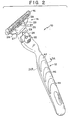
- Fig. 1 is a perspective view of a shaving razor according to the invention.
- Fig. 2 is a perspective view showing a handle and a replaceable cartridge of the Fig. 1 razor separated from each other.
- Fig. 3 is an exploded view of the components of the Fig. 2 handle.
- Figs. 4A and 4B are vertical sectional views of upper gripping pads of the Fig. 2 handle.
- Fig. 5 is a plan view of a frame of the Fig. 2 handle.
- Fig. 6 is an elevation of the Fig. 5 frame.
- Fig. 7 is a vertical sectional view, taken at 7-7 of Fig. 5, of the Fig. 5 frame.
- Fig. 8 is a partial vertical sectional view, taken at 8-8 of Fig. 6, showing the connection of locking tabs of the Figs. 4A and 4B gripping pads to the Fig. 5 frame.
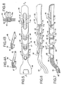
- Fig. 9 is an exploded view showing a cartridge connecting subassembly and button at a cartridge connecting end of the Fig. 5 frame of the Fig. 2 handle.
- Fig. 10 is a vertical sectional view of a base member of the Fig. 2 cartridge.
- Fig. 11 is a plan view of an ejector of the Fig. 9 subassembly.
- Fig. 12 is a horizontal section of a housing of the Fig. 9 subassembly.
- Fig. 13 is a vertical sectional view, taken at 13-13 of Fig. 12, of a housing of the Fig. 9 subassembly.
- Fig. 14 is an elevation of a plunger of the Fig. 9 subassembly.
- Fig. 15 is a plan view of the Fig. 14 plunger.
- Fig. 16 is an elevation of the button of the Fig. 2 handle.
- Fig. 17 is a vertical sectional view, taken at 17-17 of Fig. 13, of the housing of the Fig. 9 subassembly.
- shaving razor 10 includes handle 12 and replaceable shaving cartridge 14, as shown in Fig. 2, cartridge 14 is removable from handle 12.
- Cartridge 14 includes housing 16, which carries three blades 18, guard 20 and cap 22.
- Cartridge 14 also includes interconnect member 24 on which housing 16 is pivotally mounted.
- Interconnect member 24 includes base 27, which removably and fixedly attaches to cartridge connecting structure 26 of handle 12, and two arms 28 that pivotally support housing 16 at its two sides.
- Housing 16 has cam surface 25 (Fig. 2) which is acted upon by spring-biased plunger 23 of handle 12; when base 27 is connected to handle 12, plunger 23 passes through opening 29 in base 27 to bias housing 16 to the forward, at rest position shown in Fig. 1.
- Handle 12 carries button 32 used to eject a cartridge 14 by activating U-shaped ejector 86 (Fig. 9), causing it to extend from the front of cartridge connecting structure 26 and push base 27 from structure 26.
- handle 12 includes elongated hand gripping structure 30 to which cartridge connecting subassembly 31 (described in more detail below) and button 32 are connected.
- Elongated hand gripping structure 30 includes metal frame 34 as a primary structural member.
- Cartridge connecting subassembly 31 (Fig. 3) is connected to subassembly connecting end 36 of frame 34.
- End 36 is generally flat, in order to match the shape of base 27 (Figs. 1 and 2), and is offset from the rest of frame 34, which is generally straight.
- the straight portion of frame 34 has three crescent-shaped recesses 38, 40, 42 (see in particular Figs. 5-6) and associated holes 39, 41, 43 for upper, crescent-shaped gripping pads 44, 46, 48. It also includes oval shaped recess 50 for upper logo panel 52 (Fig. 3) and lower recess 54 (Fig. 7) for lower gripping pad 56, which carries lower logo pad 57 (Fig. 3).
- Upper gripping pads 44, 46, 48 and lower gripping pad 56 provide a hand-gripping structure in the completed unit and are each made of an elastomeric plastic outer gripping layer (e.g., thermoplastic elastomer) and a nonelastomeric plastic support layer (e.g., of polypropylene or acrylonitrile butadiene styrene) thereunder made by two-color molding.
- elastomeric plastic outer gripping layer e.g., thermoplastic elastomer
- a nonelastomeric plastic support layer e.g., of polypropylene or acrylonitrile butadiene styrene
- the nonelastomeric plastic support layer 47 of front gripping pad 44 has rearwardly-directed tab 62 (Fig. 4A) at the front that passes through hole 39 and mates with recess 63 on front extension 60 of lower gripping pad 56 (Fig. 3). Tab 62 is optional, and pad 44 can be securely connected to frame 34 without this feature at the front.
- the nonelastomeric plastic support layers 47 of middle and rear gripping pads 46, 48 have forwardly-directed tabs 64 (Fig. 4B) at the front that pass through holes 41, 43 and lock under overlying portions 68 of frame 34 (Fig. 7). All upper gripping pads 44, 46, 48 have facing locking tabs 70 that are received in openings 72, 74, 76 of frame 34 (Figs.
- frame 34 has opposed barbs 70a at openings 72, 74, 76, and locking tabs 70 deform as they are inserted past barbs 70a into the openings. After insertion, the portions of locking tabs 70 inside of frame 34 (in a region within frame 34 that is larger than the individual openings) return to a size that is larger than the restricted area between barbs 70a. Barbs 70a inhibit locking tabs 70 from coming out of openings 72, 74, 76 and thus lock tabs 70 and gripping pads 44, 46, 48 in position on frame 34.
- Upper logo panel 52 has extensions 58 (Fig. 3) that are press-fitted into recesses 61 in frame 34 (Figs. 5, 7).
- the nonelastomeric plastic support layer of lower gripping pad 56 has extensions 60 (Fig. 3) that are press-fitted into recesses 69 in frame 34 (Figs. 5, 7) and extensions 71 that are press-fitted between opposed mating surfaces inside of frame 34.
- Lower logo panel 57 has extensions 73 that are secured in mating recesses (not shown) in lower gripping pad 56 by staking by pins 73a.
- Subassembly 31 includes housing 82, plunger 23, spring 84, and U-shaped ejector 86. Plunger 23, spring 84, and U-shaped ejector 86 are received in recess 87 (Figs. 12, 13) in housing 82. Housing 82 includes cartridge connecting structure 26 at the front and handle connecting structure 88 at the rear, as indicated in Figs. 9 and 12. Handle connecting structure 88 has outer, handle-supporting, surfaces 90 that mate with inwardly directed handle surfaces 92 (Figs.
- Handle connecting structure 88 also has side protrusions 89 for mating with mating recesses 91 of frame 34.
- Cartridge connecting structure 26 extends from frame 34 when structure 88 is mounted in recess 80 (Fig. 2), and has outer, cartridge-supporting, side surfaces 94 (Fig. 9) that mate with inwardly directed cartridge surfaces 96 of recess 98 of base 27 (Fig. 10).
- Cartridge connecting structure 26 also includes two depressions 100 (one shown in Fig. 13) that act as cartridge holding structure for releasably holding base 27 via engagement of detents 102 (one shown in Fig. 10) thereon.
- housing 82 has assembly opening 104 (Figs. 12, 13) at the rear for receiving the movable components, namely plunger 23, spring 84, and ejector 86, during assembly.
- assembly opening 104 Figs. 12, 13
- movable components namely plunger 23, spring 84, and ejector 86
- At the front of housing 82 are side openings 106 and central opening 108 through which arm portions 110 of ejector 86 and plunger 23 are respectively movable for interaction with cartridge 14.
- Ribs 112 (Fig. 12) between openings 106, 108 act as blocking structure retaining ejector 86 and plunger 23 on housing 82.
- Arm portions 110 on each side of plunger 23 are extendible from cartridge connecting structure 26 to eject cartridge 14 from cartridge connecting structure 26.
- handle connecting structure 88 has opening 114 providing access of bottom extensions 116 of button 32 (Fig. 16) that are received within rectangular region 118 at the back narrow portion of ejector 86 (Fig. 11).
- Raised lip 120 extends above surface 90 along opening 114. Lip 120 and opening 114 are aligned with and fit within recess 122 of subassembly connecting end 36 of handle 12.
- angled stop surfaces 124 at arms 110 are biased against and blocked by angled stop surfaces 126 on the inside of recess 87. Ends 110 can be moved forward to extend slightly through openings 106 when the back of ejector 86 is pushed forward by button 32.
- Plunger 23 is located between arms 110, and front blade 128 extends through opening 108 in front of cartridge connecting structure 26. Blade 128 is thicker than the arms of ejector 86 and slides within track 129, while arms 110 slide in the narrower space between surfaces 130.
- Side projections 132 of plunger 23 (Figs.
- spring 84 is placed on shaft 140 of plunger 23, and these two components are inserted into recess 87 of housing 82 along track 129.
- U-shaped ejector 86 is then inserted, with arms 110 straddling plunger 23 in the space between surfaces 130.
- Front outer corners 142 of arms 110 are deflected inward by cam surfaces 144 of housing 82 during insertion of ejector 86.
- angled stop surfaces 124 of arms 110 pass angled stop surfaces 126 of housing 82, arms 110 spring outward, and ejector 86 is retained within housing 82 by blocking of angled stop surfaces 124 by angled stop surfaces 126. All of the movable components of subassembly 31 are thus locked within housing 82 and prevented from falling out during part handling in preparation of assembly on frame 34.
- Cartridge connecting subassembly 31 is mounted on frame 34 by inserting handle connecting structure 88 into recess 80 and staking housing 82 to frame 34 using pins 150.
- Pins 150 pass through holes 152 in frame 34 and aligned holes 154 in the upper surface 90 of handle connecting structure 88 outside of lip 120. The pins are driven into the plastic of housing 82 at lower surfaces 130 outside of the region occupied by narrow portion of U-shaped ejector 86.
- each extension 116 of ejector button 32 has an outwardly directed groove 160 that slides on a respective track 162 within opening 114.
- the upper surfaces 161 defining grooves 160 slide on the upper surfaces 164 of tracks 162, and the lower surfaces 166 defining groves 160 effect capture on or abut the lower surfaces 168 of tracks 162.
- Extensions 116 have inclined surfaces 170 that coact with the curved upper corners of tracks 162 to deflect extensions 116 inward as button 32 is inserted into opening 114.
- extensions 116 are located within rectangular region 118 and push against surfaces 172 of ejector 86 when ejector button 32 is pushed toward the end of handle 12. After button 32 has been inserted, upper vertical surfaces 174 of extensions 116 sit within the space between upper surfaces 176 of opening 114. Bar 178 serves to capture and guide spring 84.
- Button 32 covers openings 154 so that the staking is not visible in the assembled product. Also, after a cartridge 14 has been attached, no part of subassembly 31 is visible (see Fig. 1), and thus the different materials used for housing 82 and frame 34 are not evident.
Landscapes
- Engineering & Computer Science (AREA)
- Life Sciences & Earth Sciences (AREA)
- Forests & Forestry (AREA)
- Mechanical Engineering (AREA)
- Manufacturing & Machinery (AREA)
- Packaging Of Annular Or Rod-Shaped Articles, Wearing Apparel, Cassettes, Or The Like (AREA)
- Dry Shavers And Clippers (AREA)
- Pens And Brushes (AREA)
- Cosmetics (AREA)
- Surgical Instruments (AREA)
Abstract
Description
- The invention relates to shaving razors having handles and replaceable cartridges.
- Shaving systems often consist of a handle and a replaceable cartridge in which one or more blades are mounted in a plastic housing. After the blades in a cartridge have become dull from use, the cartridge is discarded, and replaced on the handle with a new cartridge. In some shaving systems the blades are resiliently mounted with respect to the cartridge housing and deflect under the force of skin contact during shaving. In some shaving systems the connection of the cartridge to the handle provides a pivotal mounting of the cartridge with respect to the handle so that the cartridge angle adjusts to follow the contours of the surface being shaved. In such systems, the cartridge can be biased toward an at rest position by the action of a spring-biased plunger (a cam follower) carried on the handle against a cam surface on the cartridge housing.
- In one aspect, the invention features, in general, a cartridge-connecting subassembly for a shaving razor handle. The cartridge connecting subassembly includes a cartridge connecting structure, a handle connecting structure, and a movable component within the cartridge connecting structure that interacts with a replaceable cartridge when it is connected. The cartridge connecting structure has outer, cartridge-supporting, side surfaces that mate with inwardly directed surfaces of a recess on the cartridge and also has cartridge holding structure that releasably holds the replaceable cartridge. The handle connecting structure has outer, handle-supporting, side surfaces that mate with inwardly directed handle surfaces of an elongated hand gripping structure of the razor handle. The cartridge connecting structure and the handle connecting structure have contiguous portions so that the subassembly is substantially covered when the handle connecting structure is connected to the elongated hand gripping structure, and the cartridge connecting structure is connected to a cartridge.
- In another aspect the invention features a cartridge-connecting subassembly for a shaving razor handle that includes a housing and a movable component within the housing. The housing includes a handle connecting structure for making a permanent connection to a subassembly connecting end of an elongated hand gripping structure of the razor handle, a cartridge connecting structure for making a releasable connection to a replaceable cartridge, an assembly opening at the handle connecting structure for receiving the movable component during assembly, a cartridge interaction opening at the cartridge connecting structure through which the component is movable for interaction with the cartridge, and blocking structure that retains the movable component on the housing.
- In another aspect, the invention features, in general, a cartridge-connecting subassembly for a shaving razor handle that includes a housing having handle connecting structure, a cartridge connecting structure on the housing, and an ejector structure that is separate from the cartridge connecting structure and is movably mounted on the housing with respect to the cartridge connecting structure so as to eject a cartridge from the cartridge connecting structure when moved to an ejection position.
- Certain implementations of the subassembly of the invention include one or more of the following features.
- In certain implementations: the movable component is a spring-biased plunger that has an end that extends from the cartridge connecting structure for biasing the cartridge; the ejector is U-shaped and has arm portions on each side of the plunger that are extendible from the cartridge connecting structure to eject a cartridge; the handle connecting structure has an opening providing access of a base portion of a button to the ejector, and the elongated hand gripping structure has a recess aligned with the opening; the handle connecting structure has a raised lip that extends above the outer, handle-supporting side surfaces; the handle connecting structure has fastener holes through the outer handle-supporting side surfaces outside of the raised lip for receiving a fastener to the elongated hand gripping structure; the handle connecting structure has side protrusions for mating with mating recesses of the inwardly directed handle surfaces; the movable member has a first cam surface and a first stop surface, and the housing has a second cam surface against which the first cam surface is deflected during insertion through the assembly opening, and the blocking structure has a second stop surface against which the first stop surface is blocked after passing the second cam surface and returning to an undeflected position, the movable member being prevented from returning through the assembly opening by interaction of the first and second stop surfaces; the blocking structure includes ribs across the interaction opening permitting passage of one part of a movable component therethrough and blocking another part of the movable component; the holding structure on the cartridge connecting structure is a depression for mating with a projection on the cartridge; alternatively, the holding structure on the cartridge connecting structure can be a projection for mating with a depression on the cartridge.
- In some other aspects, the invention features, in general, shaving razor handles including cartridge connecting subassemblies as have already been described and elongated hand gripping structure.
- In another aspect the invention features, in general, a shaving razor handle including an elongated hand gripping structure that has a generally straight portion and a subassembly connecting portion that is offset with respect to the straight portion and is generally flat. The handle also includes a subassembly that has a generally flat handle connecting structure permanently connected to the subassembly connecting portion, a cartridge connecting structure for making a releasable connection to a replaceable cartridge, and a movable component within the cartridge connecting structure for interacting with a replaceable cartridge.
- In another aspect, the invention features, in general, a shaving razor handle including an elongated hand gripping structure, a subassembly having a cartridge connecting structure and a handle connecting structure that mates with a subassembly connecting end of the elongated hand gripping structure, and a stake that permanently connects the handle connecting structure to the subassembly connecting end.
- In another aspect, the invention features, in general, a shaving razor handle including a cartridge support structure at an end of an hand gripping structure that includes a frame structure and a plurality of gripping pads. The gripping pads include an elastomeric plastic outer gripping layer and a nonelastomeric plastic support layer thereunder. The frame structure has openings that each have a restricted area leading to a larger area region within the frame structure. Each gripping pad has at least one locking tab received in a respective opening, and each locking tab has a portion that is located in the larger area region and is larger than the restricted area.
- Certain implementations of the handle of the invention may include one or more of the following features.
- In certain implementations: the restricted areas of the openings of the frame structure are defined by facing barbs; the gripping pads are crescent shaped with a broad area on an upper surface of the frame and two narrowing portions on two side portions; there is a locking at each narrowing portion; the broad area carries an interlocking portion that interlocks with structure on the frame; the nonelastomeric plastic support layer has a lower surface that is concave between the locking tabs; the frame has respective recessed areas in an outer surface; the gripping pads are located in the recessed areas.
- In another aspect, the invention features, in general, making cartridge connecting subassemblies by inserting components into housings having cartridge connecting structures and handle connecting structures as have already been described.
- In another aspect, the invention features, in general, making razor handles by securing cartridge connecting subassemblies to elongated hand gripping structures as have already been described.
- Other advantages and features of the invention will be apparent from the detailed description of preferred embodiments thereof and from the claims.
- Fig. 1 is a perspective view of a shaving razor according to the invention.
- Fig. 2 is a perspective view showing a handle and a replaceable cartridge of the Fig. 1 razor separated from each other.
- Fig. 3 is an exploded view of the components of the Fig. 2 handle.
- Figs. 4A and 4B are vertical sectional views of upper gripping pads of the Fig. 2 handle.
- Fig. 5 is a plan view of a frame of the Fig. 2 handle.
- Fig. 6 is an elevation of the Fig. 5 frame.
- Fig. 7 is a vertical sectional view, taken at 7-7 of Fig. 5, of the Fig. 5 frame.
- Fig. 8 is a partial vertical sectional view, taken at 8-8 of Fig. 6, showing the connection of locking tabs of the Figs. 4A and 4B gripping pads to the Fig. 5 frame.
- Fig. 9 is an exploded view showing a cartridge connecting subassembly and button at a cartridge connecting end of the Fig. 5 frame of the Fig. 2 handle.
- Fig. 10 is a vertical sectional view of a base member of the Fig. 2 cartridge.
- Fig. 11 is a plan view of an ejector of the Fig. 9 subassembly.
- Fig. 12 is a horizontal section of a housing of the Fig. 9 subassembly.
- Fig. 13 is a vertical sectional view, taken at 13-13 of Fig. 12, of a housing of the Fig. 9 subassembly.
- Fig. 14 is an elevation of a plunger of the Fig. 9 subassembly.
- Fig. 15 is a plan view of the Fig. 14 plunger.
- Fig. 16 is an elevation of the button of the Fig. 2 handle.
- Fig. 17 is a vertical sectional view, taken at 17-17 of Fig. 13, of the housing of the Fig. 9 subassembly.
- Referring to Figs. 1 and 2, shaving
razor 10 includeshandle 12 andreplaceable shaving cartridge 14, as shown in Fig. 2,cartridge 14 is removable fromhandle 12. Cartridge 14 includeshousing 16, which carries threeblades 18,guard 20 andcap 22. Cartridge 14 also includesinterconnect member 24 on whichhousing 16 is pivotally mounted. Interconnectmember 24 includesbase 27, which removably and fixedly attaches tocartridge connecting structure 26 ofhandle 12, and twoarms 28 that pivotally supporthousing 16 at its two sides.Housing 16 has cam surface 25 (Fig. 2) which is acted upon by spring-biased plunger 23 ofhandle 12; whenbase 27 is connected to handle 12, plunger 23 passes through opening 29 inbase 27 to biashousing 16 to the forward, at rest position shown in Fig. 1. The construction and operation of shavingcartridge 14 is discussed in detail in U.S.S.N. 08/630,437, filed April 10, 1996, which is hereby incorporated by reference as if fully set forth in its entirety herein.Handle 12 carriesbutton 32 used to eject acartridge 14 by activating U-shaped ejector 86 (Fig. 9), causing it to extend from the front ofcartridge connecting structure 26 andpush base 27 fromstructure 26. - Referring to Figs. 3-7,
handle 12 includes elongatedhand gripping structure 30 to which cartridge connecting subassembly 31 (described in more detail below) andbutton 32 are connected. Elongatedhand gripping structure 30 includesmetal frame 34 as a primary structural member. Cartridge connecting subassembly 31 (Fig. 3) is connected to subassembly connectingend 36 offrame 34.End 36 is generally flat, in order to match the shape of base 27 (Figs. 1 and 2), and is offset from the rest offrame 34, which is generally straight. The straight portion offrame 34 has three crescent-shaped recesses holes shaped gripping pads shaped recess 50 for upper logo panel 52 (Fig. 3) and lower recess 54 (Fig. 7) forlower gripping pad 56, which carries lower logo pad 57 (Fig. 3). -
Upper gripping pads lower gripping pad 56 provide a hand-gripping structure in the completed unit and are each made of an elastomeric plastic outer gripping layer (e.g., thermoplastic elastomer) and a nonelastomeric plastic support layer (e.g., of polypropylene or acrylonitrile butadiene styrene) thereunder made by two-color molding. The two-layer construction offront gripping pad 44 and rear gripping pad 48 (middle gripping pad 46 is similar to pad 48) is shown in Figs. 4A and 4B, whereelastomeric gripping layers 45 andnonelastomeric support layers 47 are shown in the sectional portions. - The nonelastomeric
plastic support layer 47 offront gripping pad 44 has rearwardly-directed tab 62 (Fig. 4A) at the front that passes throughhole 39 and mates withrecess 63 onfront extension 60 of lower gripping pad 56 (Fig. 3).Tab 62 is optional, andpad 44 can be securely connected to frame 34 without this feature at the front. The nonelastomeric plastic support layers 47 of middle and reargripping pads holes portions 68 of frame 34 (Fig. 7). All uppergripping pads tabs 70 that are received inopenings recesses frame 34 has opposedbarbs 70a atopenings tabs 70 deform as they are insertedpast barbs 70a into the openings. After insertion, the portions of lockingtabs 70 inside of frame 34 (in a region withinframe 34 that is larger than the individual openings) return to a size that is larger than the restricted area betweenbarbs 70a.Barbs 70a inhibit lockingtabs 70 from coming out ofopenings tabs 70 andgripping pads frame 34. -
Upper logo panel 52 has extensions 58 (Fig. 3) that are press-fitted intorecesses 61 in frame 34 (Figs. 5, 7). The nonelastomeric plastic support layer of lowergripping pad 56 has extensions 60 (Fig. 3) that are press-fitted intorecesses 69 in frame 34 (Figs. 5, 7) andextensions 71 that are press-fitted between opposed mating surfaces inside offrame 34.Lower logo panel 57 hasextensions 73 that are secured in mating recesses (not shown) in lowergripping pad 56 by staking by pins 73a. - Referring to Fig. 9, the components of
cartridge connecting subassembly 31 are shown prior to assembly and prior to mounting ofsubassembly 31 inrecess 80 insubassembly connecting end 36 offrame 34.Subassembly 31 includeshousing 82,plunger 23,spring 84, andU-shaped ejector 86.Plunger 23,spring 84, andU-shaped ejector 86 are received in recess 87 (Figs. 12, 13) inhousing 82.Housing 82 includescartridge connecting structure 26 at the front and handle connectingstructure 88 at the rear, as indicated in Figs. 9 and 12. Handle connectingstructure 88 has outer, handle-supporting, surfaces 90 that mate with inwardly directed handle surfaces 92 (Figs. 7, 9) offrame 34 when mounted inrecess 80. Handle connectingstructure 88 also hasside protrusions 89 for mating withmating recesses 91 offrame 34.Cartridge connecting structure 26 extends fromframe 34 whenstructure 88 is mounted in recess 80 (Fig. 2), and has outer, cartridge-supporting, side surfaces 94 (Fig. 9) that mate with inwardly directed cartridge surfaces 96 ofrecess 98 of base 27 (Fig. 10).Cartridge connecting structure 26 also includes two depressions 100 (one shown in Fig. 13) that act as cartridge holding structure for releasably holdingbase 27 via engagement of detents 102 (one shown in Fig. 10) thereon. - Referring to Figs. 9, 11-15,
housing 82 has assembly opening 104 (Figs. 12, 13) at the rear for receiving the movable components, namelyplunger 23,spring 84, andejector 86, during assembly. At the front ofhousing 82 areside openings 106 andcentral opening 108 through which armportions 110 ofejector 86 andplunger 23 are respectively movable for interaction withcartridge 14. Ribs 112 (Fig. 12) betweenopenings structure retaining ejector 86 andplunger 23 onhousing 82.Arm portions 110 on each side ofplunger 23 are extendible fromcartridge connecting structure 26 to ejectcartridge 14 fromcartridge connecting structure 26. - Referring to Figs. 9, 11 and 13, handle connecting
structure 88 hasopening 114 providing access ofbottom extensions 116 of button 32 (Fig. 16) that are received withinrectangular region 118 at the back narrow portion of ejector 86 (Fig. 11). Raisedlip 120 extends abovesurface 90 alongopening 114.Lip 120 andopening 114 are aligned with and fit withinrecess 122 ofsubassembly connecting end 36 ofhandle 12. - Referring to Figs. 11, 12, 14, 15, when
ejector 86 is mounted inrecess 87, angled stop surfaces 124 atarms 110 are biased against and blocked by angled stop surfaces 126 on the inside ofrecess 87.Ends 110 can be moved forward to extend slightly throughopenings 106 when the back ofejector 86 is pushed forward bybutton 32.Plunger 23 is located betweenarms 110, andfront blade 128 extends throughopening 108 in front ofcartridge connecting structure 26.Blade 128 is thicker than the arms ofejector 86 and slides withintrack 129, whilearms 110 slide in the narrower space between surfaces 130.Side projections 132 of plunger 23 (Figs. 14, 15) are blocked byribs 112 and prevented from further forward movement, andbottom projection 134 rides within groove 136 (Fig. 12) to guideplunger 23.Spring 84 is located onshaft 140 and pushes againstspring rest 141 at the base ofejector 86.Spring 84 thus performs the dual functions of biasingejector 86 rearward withsurfaces 124 ofejector 86 resting againstsurfaces 126 ofhousing 82 and of biasingplunger 23 forward withside projections 132 ofplunger 23 resting againstribs 112 ofhousing 82. - During assembly of
cartridge connecting subassembly 31,spring 84 is placed onshaft 140 ofplunger 23, and these two components are inserted intorecess 87 ofhousing 82 alongtrack 129.U-shaped ejector 86 is then inserted, witharms 110 straddlingplunger 23 in the space between surfaces 130. Frontouter corners 142 ofarms 110 are deflected inward bycam surfaces 144 ofhousing 82 during insertion ofejector 86. As angled stop surfaces 124 ofarms 110 pass angled stop surfaces 126 ofhousing 82,arms 110 spring outward, andejector 86 is retained withinhousing 82 by blocking of angled stop surfaces 124 by angled stop surfaces 126. All of the movable components ofsubassembly 31 are thus locked withinhousing 82 and prevented from falling out during part handling in preparation of assembly onframe 34. -
Cartridge connecting subassembly 31 is mounted onframe 34 by insertinghandle connecting structure 88 intorecess 80 and stakinghousing 82 to frame 34 usingpins 150.Pins 150 pass through holes 152 inframe 34 and alignedholes 154 in theupper surface 90 ofhandle connecting structure 88 outside oflip 120. The pins are driven into the plastic ofhousing 82 atlower surfaces 130 outside of the region occupied by narrow portion ofU-shaped ejector 86. -
Button 32 is then inserted intoopening 114. Referring to Figs. 16 and 17, eachextension 116 ofejector button 32 has an outwardly directedgroove 160 that slides on a respective track 162 withinopening 114. Theupper surfaces 161defining grooves 160 slide on the upper surfaces 164 of tracks 162, and thelower surfaces 166 defininggroves 160 effect capture on or abut thelower surfaces 168 of tracks 162.Extensions 116 have inclinedsurfaces 170 that coact with the curved upper corners of tracks 162 to deflectextensions 116 inward asbutton 32 is inserted intoopening 114. Whengrooves 160 onextensions 116 align with tracks 162,extensions 116 substantially return to their undeflected position and lockejector button 32 in place withinopening 114. The ends ofextensions 116 are located withinrectangular region 118 and push againstsurfaces 172 ofejector 86 whenejector button 32 is pushed toward the end ofhandle 12. Afterbutton 32 has been inserted, uppervertical surfaces 174 ofextensions 116 sit within the space betweenupper surfaces 176 ofopening 114. Bar 178 serves to capture and guidespring 84. -
Button 32covers openings 154 so that the staking is not visible in the assembled product. Also, after acartridge 14 has been attached, no part ofsubassembly 31 is visible (see Fig. 1), and thus the different materials used forhousing 82 andframe 34 are not evident. - Other embodiments of the invention are within the scope of the appended claims. In place of a trapezoidal extension shape for
cartridge connecting structure 26, a six-sided structure, or other asymmetrical shape could be employed.
Claims (12)
- A shaving razor handle including an elongated hand gripping structure (30), and a cartridge support structure at an end of said hand gripping structure,
characterized in that said elongated hand gripping structure includes a frame structure (4) with openings (39, 41, 43) and a plurality of gripping pads (44, 46, 48) that each comprise an elastomeric plastic outer gripping layer (45) and a nonelastomeric plastic support layer (47) thereunder, in that each said opening has a restricted area leading to a larger area region within said frame structure, and in that each said gripping pad has a locking tab (70) received in a said opening, each said locking tab having a portion that is located in said larger area region and is larger than said restricted area. - A handle according to claim 1, characterized in that the restricted area is partially defined by a barb (70a) on said frame structure (4) at said opening.
- A handle according to claim 1, characterized in that the restricted area is partially defined by facing barbs (70a) on said frame structure (4) at said opening.
- A handle according to claim 1, characterized in that at least one gripping pad has an interlocking portion that underlies an overlying portion of said frame structure.
- A handle according to claim 1, characterized in that each gripping pad has two locking tabs received in respective openings.
- A handle according to claim 5, characterized in that the nonelastomeric plastic support layer (47) has a lower surface that is concave between said locking tabs.
- A handle according to claim 2 or claim 3, characterized in that each said gripping pad has two said locking tabs received in respective said openings.
- A handle according to claim 7, characterized in that the nonelastomeric plastic support layer (47) has a lower surface that is concave between said locking tabs.
- A handle according to claim 1, characterized in that the gripping pad has two locking tabs and has an interlocking portion between said locking tabs for interlocking with structure on the frame structure.
- A handle according to claim 1, characterized in that the frame structure has respective recessed areas (38, 40, 42) in an outer surface, and said gripping pads (44, 46, 48) are located in said recessed areas.
- A handle according to claim 10, characterized in that the openings that receive respective locking tabs are located in said recessed areas.
- A handle according to claim 1, characterized in that the gripping pads are crescent shaped with a broad area on an upper surface of said frame structure and two narrowing portions on two side portions, in that there is a locking tab (70) at each narrowing portion, in that said broad area carries an interlocking portion that interlocks with structure on said frame structure, in that the nonelastomeric plastic support layer has a lower surface that is concave between said locking tabs, in that said frame structure has respective recessed areas (38, 40, 42) in an outer surface, in that said gripping pads (44, 46, 48) are located in said recessed areas, and in that said openings that receive respective said locking tabs are located in said recessed areas.
Applications Claiming Priority (3)
| Application Number | Priority Date | Filing Date | Title |
|---|---|---|---|
| US802814 | 1997-02-19 | ||
| US08/802,814 US5784790A (en) | 1996-04-10 | 1997-02-19 | Shaving razor and method |
| EP98908560A EP0969951B1 (en) | 1997-02-19 | 1998-02-18 | Shaving razor and method |
Related Parent Applications (1)
| Application Number | Title | Priority Date | Filing Date |
|---|---|---|---|
| EP98908560A Division EP0969951B1 (en) | 1997-02-19 | 1998-02-18 | Shaving razor and method |
Publications (2)
| Publication Number | Publication Date |
|---|---|
| EP1182015A1 true EP1182015A1 (en) | 2002-02-27 |
| EP1182015B1 EP1182015B1 (en) | 2003-08-13 |
Family
ID=25184781
Family Applications (2)
| Application Number | Title | Priority Date | Filing Date |
|---|---|---|---|
| EP01125253A Expired - Lifetime EP1182015B1 (en) | 1997-02-19 | 1998-02-18 | Shaving razor handle |
| EP98908560A Expired - Lifetime EP0969951B1 (en) | 1997-02-19 | 1998-02-18 | Shaving razor and method |
Family Applications After (1)
| Application Number | Title | Priority Date | Filing Date |
|---|---|---|---|
| EP98908560A Expired - Lifetime EP0969951B1 (en) | 1997-02-19 | 1998-02-18 | Shaving razor and method |
Country Status (16)
| Country | Link |
|---|---|
| US (2) | US5784790A (en) |
| EP (2) | EP1182015B1 (en) |
| JP (2) | JP4434320B2 (en) |
| CN (2) | CN1133527C (en) |
| AU (1) | AU750437B2 (en) |
| BR (1) | BR9807414A (en) |
| CA (1) | CA2279187C (en) |
| CZ (2) | CZ299092B6 (en) |
| DE (2) | DE69805292T2 (en) |
| ES (2) | ES2199915T3 (en) |
| HK (2) | HK1025283A1 (en) |
| RU (1) | RU2212996C2 (en) |
| TR (1) | TR199902027T2 (en) |
| TW (1) | TW378174B (en) |
| WO (1) | WO1998036878A2 (en) |
| ZA (1) | ZA981292B (en) |
Cited By (4)
| Publication number | Priority date | Publication date | Assignee | Title |
|---|---|---|---|---|
| WO2007000185A1 (en) * | 2005-06-28 | 2007-01-04 | Bic-Violex Sa | Ergonomic razor handle provided with an improved grip |
| US7874076B2 (en) | 2005-02-03 | 2011-01-25 | Bic Violex Sa | Razor handle having ergonomic ribbed sides |
| US7934320B2 (en) | 2005-02-03 | 2011-05-03 | Bic-Violex Sa | Razor handle having an arcuate profile |
| US7975389B2 (en) | 2005-02-03 | 2011-07-12 | Bic-Violex Sa | Razor handle having ergonomic gripping areas |
Families Citing this family (148)
| Publication number | Priority date | Publication date | Assignee | Title |
|---|---|---|---|---|
| US6041926A (en) * | 1996-04-10 | 2000-03-28 | The Gillette Company | Dispensing razor blade cartridges used with a handle |
| USD415315S (en) * | 1998-04-24 | 1999-10-12 | The Gillette Company | Razor cartridge |
| US6161287A (en) * | 1998-04-24 | 2000-12-19 | The Gillette Company | Razor blade system |
| US6615498B1 (en) | 2000-03-13 | 2003-09-09 | Warner-Lambert Company | Flexible member for a shaving razor |
| KR100352838B1 (en) * | 2000-06-24 | 2002-09-16 | 주식회사 도루코 | Shaver |
| US6749788B1 (en) | 2000-10-26 | 2004-06-15 | The Gillette Company | Method and apparatus for making a shaving razor handle |
| US20020116831A1 (en) | 2001-02-28 | 2002-08-29 | Coffin David C. | Apparatus for releasably retaining a disposable razor cartridge |
| EP1308250A1 (en) * | 2001-11-01 | 2003-05-07 | Warner-Lambert Company | Razor assembly with replaceable cartridge |
| JP3833171B2 (en) * | 2001-12-21 | 2006-10-11 | ファイザー・プロダクツ・インク | Razor device |
| US7152512B1 (en) | 2002-04-18 | 2006-12-26 | American Safety Razor | Razor handle with spring fingers |
| US7266895B2 (en) * | 2002-04-24 | 2007-09-11 | Eveready Battery Company, Inc. | Razor assembly |
| EP1586426A3 (en) * | 2002-09-13 | 2006-10-04 | Eveready Battery Company, Inc. | Razor assembly |
| US7617607B2 (en) | 2003-07-21 | 2009-11-17 | The Gillette Company | Shaving razors and other hair cutting assemblies |
| GB2406537B (en) * | 2003-07-21 | 2006-09-06 | Gillette Co | Safety razors |
| US20050022386A1 (en) * | 2003-07-29 | 2005-02-03 | Macove James A. | Razor having separate blade groups for shaving and trimming/sculpting |
| DE50313511D1 (en) * | 2003-11-18 | 2011-04-14 | Trisa Holding Ag | toothbrush body |
| US9333657B2 (en) * | 2004-01-26 | 2016-05-10 | Koninklijke Philips N.V. | Safety razor apparatus having a pivotable grip portion |
| JP4837256B2 (en) * | 2004-02-05 | 2011-12-14 | 株式会社貝印刃物開発センター | Swing razor |
| US8104184B2 (en) | 2004-03-11 | 2012-01-31 | The Gillette Company | Shaving cartridges and razors |
| AU2011202738B2 (en) * | 2004-03-11 | 2011-09-08 | The Gillette Company Llc | Shaving system |
| US20050198829A1 (en) * | 2004-03-11 | 2005-09-15 | Gray Michael J. | Shaving razor with trimming blade |
| US7690122B2 (en) | 2004-03-11 | 2010-04-06 | The Gillette Company | Shaving razor with button |
| US7168173B2 (en) * | 2004-03-11 | 2007-01-30 | The Gillette Company | Shaving system |
| US7669335B2 (en) | 2004-03-11 | 2010-03-02 | The Gillette Company | Shaving razors and shaving cartridges |
| US7475480B2 (en) * | 2004-04-05 | 2009-01-13 | The Votolato Living Trust | Disposable blade cartridge utility knife |
| US8099868B1 (en) | 2004-04-05 | 2012-01-24 | Votolato Living Trust | Disposable blade cartridge utility knife |
| WO2006086314A1 (en) * | 2005-02-07 | 2006-08-17 | American Safety Razor Company | Yoke style razor connector assembly |
| JP2006019412A (en) * | 2004-06-30 | 2006-01-19 | Canon Inc | Exposure device and manufacturing method of device |
| CA2596784A1 (en) * | 2005-02-03 | 2006-08-10 | Bic-Violex Sa | Razor handle having an air cushion finger rest area |
| BRPI0519883A2 (en) * | 2005-02-03 | 2009-09-15 | Bic Violex Sa | shaver cord |
| CN100546778C (en) * | 2005-02-03 | 2009-10-07 | 比克-维奥利克斯公司 | Razor handle with side surface of junction |
| AU2006232489B2 (en) * | 2005-04-05 | 2012-05-03 | Edgewell Personal Care Brands, Llc | Shaving implement having a moving blade |
| US7526869B2 (en) * | 2006-06-08 | 2009-05-05 | Eveready Battery Company, Inc. | Razor handle |
| JP5220768B2 (en) * | 2007-02-01 | 2013-06-26 | エバレデイ バツテリ カンパニー インコーポレーテツド | Laser handle |
| US7770294B2 (en) * | 2007-08-30 | 2010-08-10 | The Gillette Company | Razor with blade unit biasing member |
| DE102007050661A1 (en) | 2007-10-24 | 2009-04-30 | Braun Gmbh | epilator |
| US8435433B2 (en) | 2008-02-04 | 2013-05-07 | The Gillette Company | Method for making a handle for a personal grooming device |
| US20100005669A1 (en) | 2008-07-14 | 2010-01-14 | Florina Winter | Razor Handle |
| US8151468B2 (en) * | 2008-09-26 | 2012-04-10 | The Gillette Company | Handle for shaving razors having improved grip |
| MX2011003463A (en) * | 2008-10-01 | 2011-08-03 | Bic Violex Sa | Razor handles to be realeasably connected to shaving cartridges and razors including such handles. |
| AU2010203231A1 (en) * | 2009-01-05 | 2011-07-28 | The Gillette Company | Docking mechanisms for shaving razors and cartridges |
| US8826543B2 (en) * | 2009-03-23 | 2014-09-09 | The Gillette Company | Manually actuable liquid dispensing razor |
| CN201405370Y (en) * | 2009-05-18 | 2010-02-17 | 游图明 | Hand-operated shaver |
| USD625882S1 (en) | 2009-05-21 | 2010-10-19 | American Safety Razor | Shaving razor |
| US20100313426A1 (en) * | 2009-06-12 | 2010-12-16 | Terence Gordon Royle | Safety razor with pivot and rotation |
| CN101612740B (en) * | 2009-07-15 | 2012-04-25 | 宁波市开利刀片制造有限公司 | Safe shaver |
| US20110088269A1 (en) * | 2009-10-21 | 2011-04-21 | Walker Jr Vincent Paul | Docking Mechanisms for Shaving Razors and Cartridges |
| USD640414S1 (en) | 2009-11-30 | 2011-06-21 | American Safety Razor | Shaving razor |
| USD640004S1 (en) | 2009-11-30 | 2011-06-14 | American Safety Razor | Shaving razor |
| USD633252S1 (en) | 2009-11-30 | 2011-02-22 | American Safety Razor | Shaving razor |
| US8793880B2 (en) * | 2010-02-16 | 2014-08-05 | The Gillette Company | Shaving razor adapter attaching a shaving razor cartridge to a shaving razor handle |
| EP2547497A1 (en) | 2010-03-15 | 2013-01-23 | The Gillette Company | Hair removal device |
| USD636533S1 (en) | 2010-05-11 | 2011-04-19 | American Safety Razor | Razor handle |
| USD636938S1 (en) | 2010-05-12 | 2011-04-26 | American Safety Razor | Razor handle |
| USD635718S1 (en) | 2010-05-12 | 2011-04-05 | American Safety Razor | Razor handle |
| USD633253S1 (en) | 2010-06-23 | 2011-02-22 | American Safety Razor | Razor cartridge |
| USD640415S1 (en) | 2010-07-07 | 2011-06-21 | American Safety Razor | Razor cartridge |
| USD648075S1 (en) | 2010-07-07 | 2011-11-01 | American Safety Razor | Razor cartridge |
| JP5669473B2 (en) * | 2010-07-27 | 2015-02-12 | 株式会社貝印刃物開発センター | Razor handle |
| US8720072B2 (en) * | 2010-08-11 | 2014-05-13 | Thomas J. Bucco | Razor with three-axis multi-position capability |
| USD643977S1 (en) | 2010-10-19 | 2011-08-23 | American Safety Razor | Razor cartridge |
| USD643976S1 (en) | 2010-10-19 | 2011-08-23 | American Safety Razor | Razor cartridge |
| KR20130056912A (en) | 2010-10-27 | 2013-05-30 | 더 질레트 컴퍼니 | Composition dispensing device comprising a non-foaming hydrating composition |
| US9073226B2 (en) * | 2011-02-09 | 2015-07-07 | The Gillette Company | Pivoting razor |
| US20130205959A1 (en) | 2011-08-16 | 2013-08-15 | Neil John Jones | Composition Dispensing Device Comprising A Moisturizing Composition |
| US20130081275A1 (en) | 2011-09-30 | 2013-04-04 | Kevin James Wain | Lubricating member for a shaving razor |
| US20130081289A1 (en) | 2011-09-30 | 2013-04-04 | Kevin James Wain | Shaving razor handle for biasing a shaving cartridge |
| US20130081276A1 (en) | 2011-09-30 | 2013-04-04 | Kevin James Wain | Biasing shaving razors |
| US20130081291A1 (en) | 2011-09-30 | 2013-04-04 | Kevin James Wain | Biasing shaving razors |
| US9492933B2 (en) | 2011-09-30 | 2016-11-15 | The Gillette Company | Guard for a shaving razor |
| US20130081290A1 (en) * | 2011-10-03 | 2013-04-04 | Matthew Frank Murgida | Razor handle with a rotatable portion |
| US9032631B2 (en) | 2012-03-28 | 2015-05-19 | The Gillette Company | Indicia for razor with a rotatable portion |
| US20130291390A1 (en) * | 2012-05-01 | 2013-11-07 | The Gillette Company | Handle for a shaving razor |
| CN103538083B (en) * | 2012-07-13 | 2015-04-01 | 张耀灵 | Electric shaver with tool bit making reciprocating motion |
| US9283685B2 (en) | 2012-07-26 | 2016-03-15 | Shavelogic, Inc. | Pivoting razors |
| WO2014051842A1 (en) | 2012-09-27 | 2014-04-03 | Shavelogic, Inc. | Shaving systems |
| US9486930B2 (en) | 2012-09-27 | 2016-11-08 | Shavelogic, Inc. | Shaving systems |
| WO2014051843A1 (en) | 2012-09-28 | 2014-04-03 | Shavelogic, Inc. | Shaving systems |
| JP6025506B2 (en) * | 2012-11-01 | 2016-11-16 | 株式会社貝印刃物開発センター | Razor handle |
| US9623575B2 (en) | 2012-12-18 | 2017-04-18 | Shavelogic, Inc. | Shaving systems |
| US20140230256A1 (en) * | 2013-02-20 | 2014-08-21 | The Gillette Company | Hand held device |
| US20150158192A1 (en) | 2013-12-09 | 2015-06-11 | Shavelogic, Inc. | Multi-material pivot return for shaving systems |
| CN203738831U (en) * | 2013-12-31 | 2014-07-30 | 黄志坚 | Manual razor |
| BR112016018991B1 (en) * | 2014-02-28 | 2021-05-18 | Bic-Violex Sa | razor blade handle and razor blade |
| CA2941647C (en) | 2014-03-05 | 2022-10-18 | Mack-Ray, Inc. | Dual sided razor |
| USD850721S1 (en) | 2014-03-05 | 2019-06-04 | Mack-Ray, Inc. | Razor cartridge |
| US11325270B2 (en) | 2014-03-21 | 2022-05-10 | Sl Ip Company Llc | Metal spring return and method |
| EP3131717B1 (en) * | 2014-04-16 | 2019-08-28 | BIC-Violex S.A. | Handle for shaver |
| CA2955728A1 (en) * | 2014-08-04 | 2016-02-11 | Bic-Violex Sa | A razor handle comprising an insert within a hole and razor comprising such a razor handle |
| WO2016019975A1 (en) * | 2014-08-04 | 2016-02-11 | Bic-Violex Sa | A razor handle comprising an insert freely movable within a cavity and razor comprising such a razor handle |
| CN106573387B (en) * | 2014-08-07 | 2020-03-24 | 比克-维尔莱克 | Razor handle comprising an apertured element and razor comprising such a razor handle |
| US10406704B2 (en) | 2014-10-06 | 2019-09-10 | OneBlade, Inc. | Razor apparatus and shaving system |
| JP6502487B2 (en) | 2014-10-10 | 2019-04-17 | エッジウェル パーソナル ケア ブランズ リミテッド ライアビリティ カンパニーEdgewell Personal Care Brands, LLC | Universal razor cartridge handle |
| MX2017007239A (en) * | 2014-12-05 | 2017-10-16 | Bic Violex Sa | A shaver's handle with a lock and release mechanism for engaging and disengaging a razor cartridge. |
| GB201500491D0 (en) * | 2015-01-13 | 2015-02-25 | Rathbone Razor Ltd | Disposable razor |
| EP3825080A1 (en) | 2015-02-01 | 2021-05-26 | Mack-Ray, Inc. | Dual sided razor |
| EP3111995B1 (en) | 2015-06-30 | 2020-04-08 | The Gillette Company LLC | Liquid compositions for hair removal devices |
| US10131063B2 (en) * | 2015-09-29 | 2018-11-20 | The Gillette Company Llc | Adapter for attaching a razor cartridge to a razor handle |
| DE102016101672A1 (en) | 2016-01-29 | 2017-08-03 | Beiersdorf Aktiengesellschaft | Nassrasiergriff |
| WO2017137849A1 (en) | 2016-02-12 | 2017-08-17 | Gegg Peter Alexander | Adjustable body shaver, system and method |
| US11104020B2 (en) | 2016-03-04 | 2021-08-31 | Harry's, Inc. | Razor handle and method of manufacture |
| BR112018068899A2 (en) | 2016-03-18 | 2019-01-22 | Personal Care Marketing And Res Inc | razor blade cartridge |
| US11052558B2 (en) * | 2016-05-31 | 2021-07-06 | The Gillette Company Llc | Adapter for a handle and a cartridge of different razor systems |
| JP6673042B2 (en) * | 2016-06-15 | 2020-03-25 | マックス株式会社 | Gardening binding machine |
| WO2018009742A1 (en) | 2016-07-08 | 2018-01-11 | The Gillette Company Llc | Liquid compositions for hair removal devices comprising metathesized unsaturated polyol esters |
| US20180043558A1 (en) * | 2016-08-11 | 2018-02-15 | The Gillette Company | Handle for a razor |
| US10414058B2 (en) * | 2016-08-11 | 2019-09-17 | The Gillette Company Llc | Handle for a razor |
| US20180043556A1 (en) * | 2016-08-11 | 2018-02-15 | The Gillette Company | Handle for a razor |
| US11130247B2 (en) | 2016-08-11 | 2021-09-28 | The Gillette Company Llc | Handle for a razor |
| US10538005B2 (en) | 2016-10-25 | 2020-01-21 | OneBlade, Inc. | Single-blade razor apparatus |
| US9993931B1 (en) | 2016-11-23 | 2018-06-12 | Personal Care Marketing And Research, Inc. | Razor docking and pivot |
| US10800058B2 (en) * | 2017-01-17 | 2020-10-13 | The Gillette Company Llc | Method of manufacturing a liquid dispensing shaving razor |
| US10688675B2 (en) * | 2017-01-17 | 2020-06-23 | The Gillette Company Llc | Personal care bottle and method of manufacture |
| ES2927451T3 (en) | 2017-02-17 | 2022-11-07 | Leaf Shave Company | trimmer shaver |
| US10807261B2 (en) * | 2017-06-21 | 2020-10-20 | Harry's, Inc. | Razor handle |
| JP6755836B2 (en) | 2017-07-24 | 2020-09-16 | 株式会社貝印刃物開発センター | Swing razor |
| TWI642525B (en) * | 2017-08-16 | 2018-12-01 | 王嫚君 | Razor |
| KR101876233B1 (en) | 2017-09-29 | 2018-07-10 | 주식회사 도루코 | Razor cartridge assembly |
| US10357093B2 (en) | 2017-10-02 | 2019-07-23 | Billie, Inc. | Surface-mountable razor holder |
| USD866068S1 (en) * | 2018-02-20 | 2019-11-05 | The Gillette Company Llc | Razor cartridge |
| USD866070S1 (en) * | 2018-02-20 | 2019-11-05 | The Gillette Company Llc | Razor cartridge |
| USD866069S1 (en) * | 2018-02-20 | 2019-11-05 | The Gillette Company Llc | Razor cartridge |
| USD874728S1 (en) * | 2018-02-28 | 2020-02-04 | The Gillette Company Llc | Razor |
| USD877414S1 (en) * | 2018-02-28 | 2020-03-03 | The Gillette Company Llc | Razor |
| USD874729S1 (en) * | 2018-02-28 | 2020-02-04 | The Gillette Company Llc | Razor handle |
| USD905341S1 (en) | 2018-02-28 | 2020-12-15 | The Gillette Company Llc | Razor handle |
| USD874061S1 (en) | 2018-03-30 | 2020-01-28 | The Gillette Company Llc | Shaving razor cartridge |
| JP2021517045A (en) | 2018-03-30 | 2021-07-15 | ザ ジレット カンパニー リミテッド ライアビリティ カンパニーThe Gillette Company Llc | Razor handle with movable members |
| WO2019190961A1 (en) | 2018-03-30 | 2019-10-03 | The Gillette Company Llc | Razor handle with a pivoting portion |
| US11607820B2 (en) | 2018-03-30 | 2023-03-21 | The Gillette Company Llc | Razor handle with movable members |
| JP7090727B2 (en) | 2018-03-30 | 2022-06-24 | ザ ジレット カンパニー リミテッド ライアビリティ カンパニー | Razor handle with pivot part |
| JP2021517043A (en) | 2018-03-30 | 2021-07-15 | ザ ジレット カンパニー リミテッド ライアビリティ カンパニーThe Gillette Company Llc | Razor handle with pivot part |
| CA3091285A1 (en) * | 2018-03-30 | 2019-10-03 | The Gillette Company Llc | Shaving razor cartridge |
| EP3546156B1 (en) | 2018-03-30 | 2021-03-10 | The Gillette Company LLC | Razor handle with a pivoting portion |
| CN111819046B (en) | 2018-03-30 | 2022-09-13 | 吉列有限责任公司 | Razor handle with movable member |
| WO2019191345A1 (en) | 2018-03-30 | 2019-10-03 | The Gillette Company Llc | Razor handle with a pivoting portion |
| USD872365S1 (en) | 2018-05-09 | 2020-01-07 | Harry's, Inc. | Razor handle |
| EP3670119A1 (en) | 2018-12-19 | 2020-06-24 | Bic Violex S.A. | Inflatable razor |
| USD884971S1 (en) | 2019-02-27 | 2020-05-19 | Pcmr International Ltd | Razor cartridge |
| USD884970S1 (en) | 2019-02-27 | 2020-05-19 | PCMR International Ltd. | Razor cartridge guard |
| USD884969S1 (en) | 2019-02-27 | 2020-05-19 | Pcmr International Ltd | Combined razor cartridge guard and docking |
| US11020866B2 (en) * | 2019-03-15 | 2021-06-01 | The Gillette Company Llc | Handle for a razor |
| EP3744490B1 (en) * | 2019-05-29 | 2022-11-09 | BIC Violex Single Member S.A. | Handle assembly and recycling process therefor |
| EP3771530B1 (en) | 2019-07-31 | 2024-08-28 | BIC Violex Single Member S.A. | Mechanical assembly of a skin care device, skin care device and process for manufacturing thereof |
| USD940956S1 (en) | 2019-10-16 | 2022-01-11 | Yigal Mesika | Razor handle |
| USD977868S1 (en) | 2019-10-16 | 2023-02-14 | Yigal Mesika | Razor stand |
| US11000960B1 (en) | 2020-11-16 | 2021-05-11 | Personal Care Marketing And Research, Inc. | Razor exposure |
| USD1042959S1 (en) * | 2022-06-23 | 2024-09-17 | The Gillette Company Llc | Shaving razor handle |
Citations (3)
| Publication number | Priority date | Publication date | Assignee | Title |
|---|---|---|---|---|
| US630437A (en) | 1899-01-10 | 1899-08-08 | Charles J Ball | Flushing-tank. |
| US5027511A (en) * | 1990-09-28 | 1991-07-02 | The Gillette Company | Shaving system |
| US5497551A (en) * | 1994-10-13 | 1996-03-12 | The Gillette Company | Razor handle assembly |
Family Cites Families (39)
| Publication number | Priority date | Publication date | Assignee | Title |
|---|---|---|---|---|
| US2694856A (en) * | 1951-02-16 | 1954-11-23 | Gillette Co | Magazine razor |
| US3363312A (en) * | 1966-03-07 | 1968-01-16 | James J. Fayed | Safety razor with disposable wire-blade magazine and having honing means for the wire blade |
| GB1163222A (en) * | 1967-06-19 | 1969-09-04 | Gillette Industries Ltd | Improvements relating to Safety Razors |
| US3740841A (en) * | 1970-04-20 | 1973-06-26 | Philip Morris Inc | Safety razor embodying blade pressure control |
| US3795979A (en) * | 1972-04-27 | 1974-03-12 | Gillette Co | Handle |
| GB1378085A (en) * | 1972-05-16 | 1974-12-18 | Wilkinson Sword Ltd | Shaving devices |
| US3878605A (en) * | 1972-12-11 | 1975-04-22 | Philip Morris Inc | Handle construction |
| US4266340A (en) * | 1979-06-11 | 1981-05-12 | Warner-Lambert Company | Razor handle for mounting pivotable razor blade cartridges |
| US4334563A (en) * | 1980-07-21 | 1982-06-15 | The Budd Company | Swingable impact tool |
| US4446619A (en) * | 1982-06-07 | 1984-05-08 | The Gillette Company | Razor handle |
| US4514904A (en) * | 1983-09-21 | 1985-05-07 | The Gillette Company | Razor handle |
| US4599793A (en) * | 1984-05-23 | 1986-07-15 | American Safety Razor Company | Razor connector |
| GB8506831D0 (en) * | 1985-03-15 | 1985-04-17 | Wilkinson Sword Ltd | Razor handle |
| DE3518703A1 (en) * | 1985-05-24 | 1986-11-27 | Merkur Stahlwaren Wolfgang Hannemann, 5650 Solingen | HAND SHAVER |
| IT206831Z2 (en) * | 1986-04-16 | 1987-10-01 | Montana Coltelleria Spa | PROFESSIONAL, WITH COATED HANDLE KNIFE FOR HOUSEWARES AND ELASTOMERIC MATERIALS. |
| DE3635553A1 (en) * | 1986-10-20 | 1988-04-21 | Detlef Koeppen | Razor |
| US4780959A (en) * | 1987-01-27 | 1988-11-01 | Sinka Laslo B | Razor adaptor |
| JPH01285270A (en) * | 1988-05-12 | 1989-11-16 | Terumo Corp | Plug body assembly, liquid receiving container equipped therewith and preparation thereof |
| US4949457A (en) * | 1988-08-03 | 1990-08-21 | Warner-Lambert Company | Soft resilient razor handle |
| FR2639280A1 (en) * | 1988-11-24 | 1990-05-25 | Izoard Patrick | Improvements to mechanical razors, particularly disposable razors |
| JPH0632065Y2 (en) * | 1989-05-26 | 1994-08-24 | フェザー安全剃刀株式会社 | Handheld handle |
| AU638974B2 (en) * | 1989-06-05 | 1993-07-15 | Warner-Lambert Company | Razor mechanism |
| JPH0342138U (en) * | 1989-08-31 | 1991-04-22 | ||
| DE8911280U1 (en) * | 1989-09-22 | 1991-01-24 | Wilkinson Sword GmbH, 5650 Solingen | Wet shaver |
| FR2657316A1 (en) * | 1990-01-19 | 1991-07-26 | Valeo Systemes Dessuyage | WIPER BLADE AND WIPER BLADE EQUIPPED WITH SUCH BLADE. |
| US5016352A (en) * | 1990-03-22 | 1991-05-21 | The Gillette Company | Single button razor |
| US5107590A (en) * | 1991-03-26 | 1992-04-28 | Warner-Lambert Company | Razor handle |
| US5403534A (en) * | 1991-09-26 | 1995-04-04 | Tritec International Corporation | Disposable razor |
| GB9208098D0 (en) * | 1992-04-13 | 1992-05-27 | Gillette Co | Razor with movable cartridge |
| GB9221173D0 (en) * | 1992-10-08 | 1992-11-25 | Gillette Co | Shaving systems |
| US5331740A (en) * | 1992-10-08 | 1994-07-26 | The Gillette Company | Shaving system |
| JPH06335576A (en) * | 1993-05-27 | 1994-12-06 | Ikeda Bussan Co Ltd | Pull-in structure of sheet trim cover |
| US6026577A (en) * | 1993-10-15 | 2000-02-22 | Warner-Lambert Company | Disposable razor with removable razor head |
| JPH0728049U (en) * | 1993-10-27 | 1995-05-23 | 花王株式会社 | cap |
| US5347717A (en) * | 1993-11-05 | 1994-09-20 | Ts Ai Tse Jen | Chuck assembly for a disposable razor |
| FR2714863B1 (en) * | 1994-01-11 | 1996-03-29 | Facom | Tool handle. |
| US5600887A (en) * | 1995-05-26 | 1997-02-11 | Olson; Brad | Flexible easy-rinsing razor |
| AU6502296A (en) * | 1995-09-01 | 1997-03-27 | Warner-Lambert Company | Multiple piece handle for disposable razor |
| US5687485A (en) * | 1996-05-15 | 1997-11-18 | The Gillette Company | Razor handle |
-
1997
- 1997-02-19 US US08/802,814 patent/US5784790A/en not_active Expired - Lifetime
- 1997-05-10 TW TW086106238A patent/TW378174B/en active
-
1998
- 1998-02-12 US US09/022,744 patent/US5890296A/en not_active Expired - Lifetime
- 1998-02-17 ZA ZA9801292A patent/ZA981292B/en unknown
- 1998-02-18 DE DE69805292T patent/DE69805292T2/en not_active Expired - Lifetime
- 1998-02-18 ES ES01125253T patent/ES2199915T3/en not_active Expired - Lifetime
- 1998-02-18 AU AU66564/98A patent/AU750437B2/en not_active Expired
- 1998-02-18 RU RU99120114/12A patent/RU2212996C2/en active
- 1998-02-18 DE DE69817230T patent/DE69817230T2/en not_active Expired - Lifetime
- 1998-02-18 JP JP53676398A patent/JP4434320B2/en not_active Expired - Lifetime
- 1998-02-18 CA CA002279187A patent/CA2279187C/en not_active Expired - Lifetime
- 1998-02-18 EP EP01125253A patent/EP1182015B1/en not_active Expired - Lifetime
- 1998-02-18 CZ CZ20030339A patent/CZ299092B6/en not_active IP Right Cessation
- 1998-02-18 CN CNB98802683XA patent/CN1133527C/en not_active Expired - Lifetime
- 1998-02-18 TR TR1999/02027T patent/TR199902027T2/en unknown
- 1998-02-18 ES ES98908560T patent/ES2176978T3/en not_active Expired - Lifetime
- 1998-02-18 CN CNB031328504A patent/CN1260048C/en not_active Expired - Lifetime
- 1998-02-18 WO PCT/US1998/002948 patent/WO1998036878A2/en active Application Filing
- 1998-02-18 BR BR9807414A patent/BR9807414A/en not_active IP Right Cessation
- 1998-02-18 CZ CZ0266299A patent/CZ299729B6/en not_active IP Right Cessation
- 1998-02-18 EP EP98908560A patent/EP0969951B1/en not_active Expired - Lifetime
-
2000
- 2000-07-10 HK HK00104227A patent/HK1025283A1/en not_active IP Right Cessation
-
2002
- 2002-08-02 HK HK02105684A patent/HK1044310A1/en not_active IP Right Cessation
-
2005
- 2005-02-17 JP JP2005040822A patent/JP4526973B2/en not_active Expired - Lifetime
Patent Citations (3)
| Publication number | Priority date | Publication date | Assignee | Title |
|---|---|---|---|---|
| US630437A (en) | 1899-01-10 | 1899-08-08 | Charles J Ball | Flushing-tank. |
| US5027511A (en) * | 1990-09-28 | 1991-07-02 | The Gillette Company | Shaving system |
| US5497551A (en) * | 1994-10-13 | 1996-03-12 | The Gillette Company | Razor handle assembly |
Cited By (5)
| Publication number | Priority date | Publication date | Assignee | Title |
|---|---|---|---|---|
| US7874076B2 (en) | 2005-02-03 | 2011-01-25 | Bic Violex Sa | Razor handle having ergonomic ribbed sides |
| US7934320B2 (en) | 2005-02-03 | 2011-05-03 | Bic-Violex Sa | Razor handle having an arcuate profile |
| US7975389B2 (en) | 2005-02-03 | 2011-07-12 | Bic-Violex Sa | Razor handle having ergonomic gripping areas |
| WO2007000185A1 (en) * | 2005-06-28 | 2007-01-04 | Bic-Violex Sa | Ergonomic razor handle provided with an improved grip |
| US7861419B2 (en) * | 2005-06-28 | 2011-01-04 | Bic Violex Sa | Ergonomic razor handle provided with an improved grip |
Also Published As
Similar Documents
| Publication | Publication Date | Title |
|---|---|---|
| US5890296A (en) | Razor handle | |
| EP1226904B2 (en) | Shaving system | |
| US7770294B2 (en) | Razor with blade unit biasing member | |
| CA2447158C (en) | Shaving razor handle | |
| AU774120B2 (en) | Shaving Razor | |
| MXPA99007651A (en) | Shaving razor and method |
Legal Events
| Date | Code | Title | Description |
|---|---|---|---|
| PUAI | Public reference made under article 153(3) epc to a published international application that has entered the european phase |
Free format text: ORIGINAL CODE: 0009012 |
|
| AC | Divisional application: reference to earlier application |
Ref document number: 969951 Country of ref document: EP |
|
| AK | Designated contracting states |
Kind code of ref document: A1 Designated state(s): DE ES FR GB IT SE |
|
| 17P | Request for examination filed |
Effective date: 20020725 |
|
| AKX | Designation fees paid |
Free format text: DE ES FR GB IT SE |
|
| GRAH | Despatch of communication of intention to grant a patent |
Free format text: ORIGINAL CODE: EPIDOS IGRA |
|
| RIN1 | Information on inventor provided before grant (corrected) |
Inventor name: TROTTA, ROBERT A. Inventor name: WORRICK, CHARLES B. Inventor name: METCALF, STEPHEN C. Inventor name: CARSON III, WILLIAM C. Inventor name: LEE, ALEJANDRO C. Inventor name: NOWAK, PAUL |
|
| GRAH | Despatch of communication of intention to grant a patent |
Free format text: ORIGINAL CODE: EPIDOS IGRA |
|
| GRAA | (expected) grant |
Free format text: ORIGINAL CODE: 0009210 |
|
| AC | Divisional application: reference to earlier application |
Ref document number: 0969951 Country of ref document: EP Kind code of ref document: P |
|
| AK | Designated contracting states |
Designated state(s): DE ES FR GB IT SE |
|
| REG | Reference to a national code |
Ref country code: GB Ref legal event code: FG4D |
|
| REF | Corresponds to: |
Ref document number: 69817230 Country of ref document: DE Date of ref document: 20030918 Kind code of ref document: P |
|
| REG | Reference to a national code |
Ref country code: SE Ref legal event code: TRGR |
|
| REG | Reference to a national code |
Ref country code: ES Ref legal event code: FG2A Ref document number: 2199915 Country of ref document: ES Kind code of ref document: T3 |
|
| ET | Fr: translation filed | ||
| PLBE | No opposition filed within time limit |
Free format text: ORIGINAL CODE: 0009261 |
|
| STAA | Information on the status of an ep patent application or granted ep patent |
Free format text: STATUS: NO OPPOSITION FILED WITHIN TIME LIMIT |
|
| 26N | No opposition filed |
Effective date: 20040514 |
|
| REG | Reference to a national code |
Ref country code: HK Ref legal event code: GR Ref document number: 1044310 Country of ref document: HK |
|
| PGFP | Annual fee paid to national office [announced via postgrant information from national office to epo] |
Ref country code: FR Payment date: 20110201 Year of fee payment: 14 Ref country code: SE Payment date: 20110209 Year of fee payment: 14 Ref country code: IT Payment date: 20110219 Year of fee payment: 14 |
|
| PGFP | Annual fee paid to national office [announced via postgrant information from national office to epo] |
Ref country code: ES Payment date: 20110216 Year of fee payment: 14 |
|
| PG25 | Lapsed in a contracting state [announced via postgrant information from national office to epo] |
Ref country code: SE Free format text: LAPSE BECAUSE OF NON-PAYMENT OF DUE FEES Effective date: 20120219 |
|
| REG | Reference to a national code |
Ref country code: FR Ref legal event code: ST Effective date: 20121031 |
|
| PG25 | Lapsed in a contracting state [announced via postgrant information from national office to epo] |
Ref country code: IT Free format text: LAPSE BECAUSE OF NON-PAYMENT OF DUE FEES Effective date: 20120218 |
|
| PG25 | Lapsed in a contracting state [announced via postgrant information from national office to epo] |
Ref country code: FR Free format text: LAPSE BECAUSE OF NON-PAYMENT OF DUE FEES Effective date: 20120229 |
|
| REG | Reference to a national code |
Ref country code: ES Ref legal event code: FD2A Effective date: 20130709 |
|
| PG25 | Lapsed in a contracting state [announced via postgrant information from national office to epo] |
Ref country code: ES Free format text: LAPSE BECAUSE OF NON-PAYMENT OF DUE FEES Effective date: 20120219 |
|
| REG | Reference to a national code |
Ref country code: DE Ref legal event code: R081 Ref document number: 69817230 Country of ref document: DE Owner name: THE GILLETTE COMPANY LLC (N. D. GES. D. STAATE, US Free format text: FORMER OWNER: THE GILLETTE COMPANY, BOSTON, MASS., US |
|
| PGFP | Annual fee paid to national office [announced via postgrant information from national office to epo] |
Ref country code: DE Payment date: 20170227 Year of fee payment: 20 |
|
| PGFP | Annual fee paid to national office [announced via postgrant information from national office to epo] |
Ref country code: GB Payment date: 20170126 Year of fee payment: 20 |
|
| REG | Reference to a national code |
Ref country code: GB Ref legal event code: 732E Free format text: REGISTERED BETWEEN 20170622 AND 20170628 |
|
| REG | Reference to a national code |
Ref country code: DE Ref legal event code: R071 Ref document number: 69817230 Country of ref document: DE |
|
| REG | Reference to a national code |
Ref country code: GB Ref legal event code: PE20 Expiry date: 20180217 |
|
| PG25 | Lapsed in a contracting state [announced via postgrant information from national office to epo] |
Ref country code: GB Free format text: LAPSE BECAUSE OF EXPIRATION OF PROTECTION Effective date: 20180217 |