EP1181949B1 - Multichannel stimulator electronics - Google Patents
Multichannel stimulator electronics Download PDFInfo
- Publication number
- EP1181949B1 EP1181949B1 EP01119556A EP01119556A EP1181949B1 EP 1181949 B1 EP1181949 B1 EP 1181949B1 EP 01119556 A EP01119556 A EP 01119556A EP 01119556 A EP01119556 A EP 01119556A EP 1181949 B1 EP1181949 B1 EP 1181949B1
- Authority
- EP
- European Patent Office
- Prior art keywords
- electrode
- electrodes
- stimulation
- stimulator
- pulse
- Prior art date
- Legal status (The legal status is an assumption and is not a legal conclusion. Google has not performed a legal analysis and makes no representation as to the accuracy of the status listed.)
- Expired - Lifetime
Links
Images


Classifications
-
- A—HUMAN NECESSITIES
- A61—MEDICAL OR VETERINARY SCIENCE; HYGIENE
- A61N—ELECTROTHERAPY; MAGNETOTHERAPY; RADIATION THERAPY; ULTRASOUND THERAPY
- A61N1/00—Electrotherapy; Circuits therefor
- A61N1/18—Applying electric currents by contact electrodes
- A61N1/32—Applying electric currents by contact electrodes alternating or intermittent currents
- A61N1/36—Applying electric currents by contact electrodes alternating or intermittent currents for stimulation
- A61N1/3605—Implantable neurostimulators for stimulating central or peripheral nerve system
- A61N1/3606—Implantable neurostimulators for stimulating central or peripheral nerve system adapted for a particular treatment
- A61N1/36067—Movement disorders, e.g. tremor or Parkinson disease
-
- A—HUMAN NECESSITIES
- A61—MEDICAL OR VETERINARY SCIENCE; HYGIENE
- A61N—ELECTROTHERAPY; MAGNETOTHERAPY; RADIATION THERAPY; ULTRASOUND THERAPY
- A61N1/00—Electrotherapy; Circuits therefor
- A61N1/02—Details
- A61N1/04—Electrodes
- A61N1/05—Electrodes for implantation or insertion into the body, e.g. heart electrode
- A61N1/056—Transvascular endocardial electrode systems
-
- A—HUMAN NECESSITIES
- A61—MEDICAL OR VETERINARY SCIENCE; HYGIENE
- A61N—ELECTROTHERAPY; MAGNETOTHERAPY; RADIATION THERAPY; ULTRASOUND THERAPY
- A61N1/00—Electrotherapy; Circuits therefor
- A61N1/18—Applying electric currents by contact electrodes
- A61N1/32—Applying electric currents by contact electrodes alternating or intermittent currents
- A61N1/36—Applying electric currents by contact electrodes alternating or intermittent currents for stimulation
- A61N1/3605—Implantable neurostimulators for stimulating central or peripheral nerve system
- A61N1/36128—Control systems
- A61N1/36135—Control systems using physiological parameters
-
- A—HUMAN NECESSITIES
- A61—MEDICAL OR VETERINARY SCIENCE; HYGIENE
- A61N—ELECTROTHERAPY; MAGNETOTHERAPY; RADIATION THERAPY; ULTRASOUND THERAPY
- A61N1/00—Electrotherapy; Circuits therefor
- A61N1/18—Applying electric currents by contact electrodes
- A61N1/32—Applying electric currents by contact electrodes alternating or intermittent currents
- A61N1/36—Applying electric currents by contact electrodes alternating or intermittent currents for stimulation
- A61N1/36003—Applying electric currents by contact electrodes alternating or intermittent currents for stimulation of motor muscles, e.g. for walking assistance
-
- A—HUMAN NECESSITIES
- A61—MEDICAL OR VETERINARY SCIENCE; HYGIENE
- A61N—ELECTROTHERAPY; MAGNETOTHERAPY; RADIATION THERAPY; ULTRASOUND THERAPY
- A61N1/00—Electrotherapy; Circuits therefor
- A61N1/18—Applying electric currents by contact electrodes
- A61N1/32—Applying electric currents by contact electrodes alternating or intermittent currents
- A61N1/36—Applying electric currents by contact electrodes alternating or intermittent currents for stimulation
- A61N1/3605—Implantable neurostimulators for stimulating central or peripheral nerve system
- A61N1/36128—Control systems
- A61N1/36146—Control systems specified by the stimulation parameters
- A61N1/36182—Direction of the electrical field, e.g. with sleeve around stimulating electrode
- A61N1/36185—Selection of the electrode configuration
Definitions
- the present invention relates to a tissue stimulation system.
- the concept of using electronic stimulation systems for the purpose of controlling nerves or muscles is well known. These systems typically utilize an implantable or an external pulse generator.
- the external systems consist of a transmitter and antenna which transmits energy and/or stimulation signals transcutaneously through a patient's skin to an implanted receiver.
- the receiver provides signal processing of the received pulses and transmits the energy derived therefrom to activate electrodes implanted adjacent to specific types of tissue to be stimulated.
- a system like the one described above has been disclosed previously in U.S. Patent 3,727,616. It is also known in prior art where more than one pair of electrodes are activated such as Patent 3,449,768.
- Electrode placement fails to provide the desired physical response. It may also occur later if a change in patient condition or change in electrode position occurs. This failure may also be caused by improper polarity of the stimulated electrodes relative to one another.
- the electrodes be implanted surgically adjacent to one or more nerve fibers. This type of procedure involves inherent risks due to the fact that it is often performed in close proximity to the brain or spinal cord or other sensitive nerves or tissues. It is therefore desirable to perform the electrode implantation only once to minimize the surgical risks to the patient as well as the financial burdens.
- the Borkan patent '934 provides programming to the surgically implanted stimulator receiver to define electrode selection and polarity and stimulation pulse parameters.
- the pulse parameters included frequency, amplitude and pulse width.
- the impedance of the electrodes are measured and used to modify the programmed stimulation pulse as were inputs from measured physical parameters.
- a single stimulation pulse was developed and provided to any or all the selected electrode combinations. There was not the ability to provide individual pulses simultaneously to different selected electrodes. Also, the impedance of the individual electrodes were not measured, but only the electrodes as a group.
- An edge-effect electrode producing spatially controlled distributions of electric potentials in volume conductive media is described in U.S. Patent 5,649,970.
- a plurality of electrodes are spaced along an elongated stimulation lead.
- tissue stimulation system in accordance with the present invention is defined in claim 1, preferred embodiments being set forth in the dependent claims. Other embodiments described in the following are not encompassed by the present invention.
- a tissue stimulation system includes an electrode assembly having at least three electrodes spaced to be stimulated in a patient.
- a programmable stimulator is connected to and provides stimulation pulses to the electrode assembly.
- Programming data in the stimulator define, for each of the electrodes, individual stimulation pulses of varying polarity and at least one of amplitude, frequency, pulse width and pulse shape.
- the stimulator may include a pulse generator for each of the electrodes, or a common pulse generator for all the electrodes and a variable impedance circuitry for each of the electrodes.
- a variable impedance circuit may include a voltage divider or an analog switch, for example. The stimulator would individually control the amplitude and pulse width using the variable impedance circuit.
- the stimulator can measure the impedance of each of the electrodes and modifies the stimulation pulse for each electrode defined by the programming data as a function of the measured impedance of that electrode.
- the stimulator may measure physical or physiological parameters and modifies the stimulation pulse for each electrode defined by the parameter data as a function of the measured parameters.
- the measured parameters may include one of the following: EMG, EKG, or EEG measurements.
- the measurement circuit may include chemical or biochemical sensors.
- the stimulator includes a signal input and modifies the stimulation pulses as a function of input signals on the signal input.
- the input signals may include processed audio or visual signals.
- the stimulator may determine the position of the electrode from the measured parameters and modifies the stimulation pulses as a function of the determined position.
- a display is provided for showing the determined position.
- An additional electrode spaced from the at least three electrodes is provided.
- the additional electrode has a surface area greater than the surface area of each of the at least three electrodes.
- the additional electrode is at least twice the surface area of each of the at least three electrodes.
- the additional electrode is spaced from the at least three electrode by at least 10 millimeters.
- the programming data defines bipolar mode, monopolar mode and simultaneous bipolar/monopolar mode stimulation.
- the bipolar mode uses at least two of the at least three electrodes and the monopolar mode uses the additional electrode as an anode electrode and at least one of the at least three electrodes as a cathode electrode.
- the present tissue stimulation system maybe used to perform a method of tissue stimulation by positioning the electrode assembly with the electrodes lying along a tissue to be stimulated in the patient and the stimulator connected to the electrodes.
- Stimulation pulses are provided from the stimulator to the at least three electrodes with independently assigned polarity and at least one of amplitude, frequency, pulse width and pulse shape.
- the stimulator may be external or preferably implanted.
- the method may further include measuring the series impedance of each of the electrodes and modifying the stimulation pulse for each electrode defined as a function of the measured impedance of that electrode.
- the measured parameters may include one of the following: EMG, EKG, or EEG measurements.
- Information may be obtained from at least one of pulmonary, cardiac or neuro monitors; and the stimulation pulses are modified as a function of the information and measured parameters.
- the relative position of the electrodes to the desired tissue to be stimulated may be determined using the measured parameters.
- the determined electrode's relative position may be displayed.
- the display may show overlays of an image of the desired electrode position and/or movement on an x-ray or fluoroscopic image.
- the system provides feedback to a physician as the electrode is moved in real time.
- the stimulation pulses may be modified as a function of the relative position.
- the measuring may include EMG measurements of specific muscles.
- the stimulation pulses are modified to determine the relative position of one or more of the individual electrodes.
- the method may also include simultaneously providing stimulation pulses to at least two of the at least three electrodes in a bipolar mode and to an additional electrode as an anode and at least one of the at least three electrodes as a cathode in a monopolar mode.
- Electrodes used for spinal cord stimulation are typically implanted in the epidural space. This is done for various reasons, including reduced complexity of the surgery, reduced potential complications, an increased stability of the implant.
- implantation in the epidural space requires a significant amount of additional stimulation power since the signal must be transmitted through the dura and cerebrospinal fluid in order to reach its desired neural targets in the spinal cord.
- the object of the present invention is to provide additional and more sensitive methods to move the stimulation field (and therefore the activated neural fibers and tissues) to achieve effective therapy.
- the present invention alters the size, shape, and position of the electrical field by changing the relative amplitude or impedance of the stimulation pulse for the stimulated electrodes individually. For instance, if four electrodes are activated-two as cathodes and two as anodes - the electrical field may be altered by changing the relative amplitude, pulse width and/or pulse shape delivered to the individual electrodes.
- the present invention provides the highly refined targeting capabilities for optimal therapeutic results.
- Use of independent amplitude control allows reprogramming of an electrode array to compensate for less than optimal position relative to the targeted neural fibers. For instance, two catheters placed off the midline of the spinal cord may stimulate undesirable nerve roots at the levels required to activate desired longitudinal fibers making it impossible to achieve acceptable therapeutic results with a conventional stimulator. By changing the relative amplitude of the stimulation pulse for the electrodes individually the stimulation field can be moved to avoid activating the undesirable fibers.
- Some nerve fibers are more sensitive to different pulse shapes or pulse widths. Altering these parameters for each electrode individually allows more selective activation of desired neural targets while minimizing activation of undesirable structures.
- the method could further include measuring certain physical or physiological parameters and modifying the stimulation pulses based on these measurements. For instance, during implantation of a spinal cord stimulator, placement of the electrode at a specific dermatomal location and/or lateral position relative to the spinal cord is critical. Measurement of stimulation induced muscle contractions by a series of individually generated stimulation pulses can be performed such that a system to indicate when the desired location is achieved based on physiological measurements becomes practical. Without individual pulse parameter control, this procedure would be time consuming, impractical and in many instances impossible.
- a stimulator 10 is shown in Figure 1 as including a microprocessor and control circuit 20 having programming data 22 stored therein.
- the programming data determines which electrodes are to be stimulated, the polarity of the electrodes relative to each other, and the stimulator pulse to be applied to each of the individual electrodes defined.
- the programming data is shown stored in the circuit, it could be stored externally or downloaded from an external source via interface 25. The data may be downloaded on a pulse to pulse basis, for instance in an auditory or visual prosthetic application.
- the microprocessor and control circuit 20 may also include measurement circuits to measure the impedance of each electrode through electrode impedance measurement circuit 24 which senses the impedance of each of the individual electrode. It may also monitor physical or physiological parameters using measurement circuit 26.
- the measurement circuit 26 may include chemical or biochemical sensors. These physical parameters may be biological parameters or other information.
- the measured parameters may include one of the following: EMG, EKG, or EEG measurements received via interface 25. Information may be obtained via interface 25 from at least one of pulmonary, cardiac or neuro monitors.
- the relative position of the electrodes to the desired tissue to be stimulated may be determined using the measured parameters.
- the stimulation pulses may be modified as a function of the relative position.
- the measuring may include EMG measurements of specific muscles.
- the stimulation pulses are modified to determine the relative position of one or more of the individual electrodes.
- the determined electrode's relative position may be displayed.
- the display 27 may show overlays an image of the desired electrode position and/or movement on an x-ray or fluoroscopic image. The system provides feedback to a physician as the electrode is moved in real time.
- the microprocessor and control circuit 20 may modify the programming data 22 based on one or all of these measured parameters as well as the determined position. This will vary which electrodes are to be stimulated, their polarity relative to each other and the stimulation pulse for each of the individual electrodes.
- the measured parameters may be stored and/or transmitted via the interface 25.
- Control information is provided from the microprocessor and control circuit 20 to a pulse generator 30 via line 28 and to an output circuit 40 via line 29 for each electrode.
- the pulse generator 30 provides a stimulation pulse to the output circuit 40 via line 31.
- the outputs 50 of the output circuits 40 are connected to individual electrodes. There is a pulse generator 30 and an output circuit 40 for each of the individual electrodes. Three are shown for sake of clarity. This system allows each of the individual electrodes to have its individually defined pulse generator.
- FIG. 2 shows further details of the pulse generator 30 and the output circuit 40.
- the pulse generator 30 includes also a pulse amplitude defining circuit 32, pulse shape defining circuit 34, frequency defining circuit 36 and a pulse width defining circuit 38. Control of each of these are from the microprocessor and control circuit 20 via line 28.
- the output circuit 40 also includes an electrode polarity circuit 42 receiving controls from the microprocessor and control circuit 20 via line 29.
- the output of the electrode polarity circuit 42 is provided via line 41 to the output switch 44.
- the pulse on line 31 from the pulse generator 30 may be transmitted by the output switch 44 to the electrode at output 50, depending upon the polarity or high impedance as determined by electrode polarity circuit 42.
- the electrode may either be in a positive, negative or high impedance state.
- a modification is illustrated in Figure 3.
- a common pulse generator which includes the circuits 34, 36 of Figure 2 provides at line 35 to the output switch 44 a pulse of a shape and frequency defined by the control on line 28 from the microprocessor and control circuitry 20.
- the pulse amplitude defining circuit 32 also provides an output on line 33 to the output switch 44 as does pulse width defining circuit 38 via output on line 39.
- the pulse amplitude defining circuit 32 and pulse width defining circuit 38 modify the common pulse received on line 35 by controlling the output switch 44.
- the amplitude input via line 33 could control a variable impedance network, which may be a resister divider array controlled by a multiplexer.
- the pulse width input via line 39 controls the on/off of the switch to determine the pulse width. This could also generate a timing change in the delivered pulses (starting later and ending sooner than other outputs).
- the polarity is still determined by electrode polarity circuit 42.
- a digital to analog converter 43 receives a pulse amplitude signal over line 33 and the pulse width signal over line 39. This is converted to an analog signal on line 45.
- the analog signal on line 45 is provided to a variable impedance circuit 46, which also receives the common pulse on line 35, and controls the variable impedance circuit 46 to modify the common pulse.
- the individual designed pulse is then provided via line 47 to a polarity switch 48 which receives the polarity control on line 41.
- the output is provided on output 50 to the individual electrode.
- the pulse width control on line 39 may be used with logic to control the polarity switch 48.
- the variable impedance network may be a switch, for example an FET operated in the analog region.
- the analog switch impedance can vary from ON, being less than 10 ⁇ , to an off, being greater than 1 M ⁇ .
- the variable impedance would typically operate in the range of a few hundred to a few thousand ohms range. This will produce a voltage divider effect since the nerve tissue being stimulated has a nominal impedance of 500-1200 ⁇ .
- the measurement circuits 24, 26 could be implemented to interact with the implanted microprocessor and control circuit 20 to automatically reprogram the stimulation parameters. This would dynamically reprogram a stimulation regimen in response to measured parameters to a programmed level.
- the methods described herein may also be performed wherein the stimulator 10 is external the patient.
- the polarity switch is illustrated in Figure 5 as including a pair of complementary field effect transistors 52 and 54 connected in parallel and receiving an analog stimulation pulse on line 39 to be transmitted depending upon the inputs Q P and Q P ⁇ at the respective gates.
- the output is connected through capacitor 49 to the electrode output 50.
- a third FET 56 is connected between the capacitor 49 and ground and controlled at its gate by input Q N ⁇ . If Q N is high, the output polarity is positive. If Q P is high, the output is negative. If Q N and Q P are both high, the output is open or high impedance.
- the present stimulator system has been designed to allow the capability of providing individually designed stimulation pulses for each of the electrodes, the system could operate as a conventional neurostimulator system using delivery of a common stimulation pulse to select electrodes.
- a stimulation lead 60 includes a sheath 62 having a plurality of in-line electrodes 64 mutually spaced by a distance D 1 and an additional electrode 65 on a sheath wire extension 67 extending from the distal end 66.
- the proximal end 68 has contacts 69 connected to each electrode and to the stimulator outputs 50.
- the additional electrode 65 has a greater surface area on the sheath/wire than the surface area on the sheath of each of the electrodes 64.
- the electrodes 64 all may have a length L 1 and the additional electrode 65 has a length L 2 .
- Length L 2 is greater than L 1 , at least twice its length. Thus, for example, if length L 1 is 2 mm, the length L 2 is 4 mm.
- the length L 2 may be anywhere between 2-4 times that of the length L 1 .
- the additional electrode 65 may have a greater circumferential dimension than each of the electrodes 64.
- the additional electrode 65 may have a 360° circumference and the electrodes 64 be 180° or less, for example.
- the additional electrode 65 is spaced by a distance D 2 from the nearest electrode 64. Where D 1 is approximately 6 mm, the distance D 2 is at least 10 mm and can be as much as 20 mm or more. With this distance, the electrodes 64 each acts as a point source when used in conjunction with the additional electrode 65 of the increased area.
- Electrodes may be used with the stimulator system of the present invention.
- This is an example of an electrode which is capable of simultaneous operation in a bipolar mode and a monopolar mode as well as each mode alone.
- the bipolar mode at least two of the electrodes 64 are used while in the monopolar mode, the additional electrode 65 is used as an anode with at least one of the electrodes 64 as a cathode.
- the individual programming of the stimulation pulse allows this to occur.
- These stimulation paradigms could include sophisticated programs that switch stimulation between a number of electrodes slowly (over seconds or minutes, hours or days) to avoid accommodation of the stimulation or to treat multiple neural targets, or could be fast (approximately the same speed of the electrical activity of neurons in the spinal cord) artificially generating neural signals along the spinal cord or a nerve which could be perceived as any other sensory function with signals that travel through the spinal cord or nerve.
- a signal could be generated that would correspond to heat being applied to a patient's big toe, or pressure being applied to a patient's foot, or the sensation of a limb in a different orientation than it actually is.
Landscapes
- Health & Medical Sciences (AREA)
- Life Sciences & Earth Sciences (AREA)
- Nuclear Medicine, Radiotherapy & Molecular Imaging (AREA)
- General Health & Medical Sciences (AREA)
- Neurology (AREA)
- Neurosurgery (AREA)
- Engineering & Computer Science (AREA)
- Biomedical Technology (AREA)
- Veterinary Medicine (AREA)
- Radiology & Medical Imaging (AREA)
- Animal Behavior & Ethology (AREA)
- Public Health (AREA)
- Heart & Thoracic Surgery (AREA)
- Physiology (AREA)
- Biophysics (AREA)
- Vascular Medicine (AREA)
- Cardiology (AREA)
- Hospice & Palliative Care (AREA)
- Electrotherapy Devices (AREA)
Abstract
Description
- The present invention relates to a tissue stimulation system.
- The concept of using electronic stimulation systems for the purpose of controlling nerves or muscles is well known. These systems typically utilize an implantable or an external pulse generator. The external systems consist of a transmitter and antenna which transmits energy and/or stimulation signals transcutaneously through a patient's skin to an implanted receiver. The receiver provides signal processing of the received pulses and transmits the energy derived therefrom to activate electrodes implanted adjacent to specific types of tissue to be stimulated. A system like the one described above has been disclosed previously in U.S. Patent 3,727,616. It is also known in prior art where more than one pair of electrodes are activated such as Patent 3,449,768.
- Problems arise in these prior art systems where electrode placement fails to provide the desired physical response. It may also occur later if a change in patient condition or change in electrode position occurs. This failure may also be caused by improper polarity of the stimulated electrodes relative to one another. Furthermore, it is often required that the electrodes be implanted surgically adjacent to one or more nerve fibers. This type of procedure involves inherent risks due to the fact that it is often performed in close proximity to the brain or spinal cord or other sensitive nerves or tissues. It is therefore desirable to perform the electrode implantation only once to minimize the surgical risks to the patient as well as the financial burdens.
- Moreover, even when a plurality of electrodes have been utilized, such that repeated surgical procedures are not required, the prior art systems did not provide for dynamic programming and reprogramming of different electrodes after surgery until U.S. Patent 4,459,989 to Borkan. The Borkan patent '989 disclosed an external stimulator system which allowed noninvasive programming of the stimulated electrodes. Each electrode was capable of assuming a positive, negative or open circuit status with respect to the other electrodes. This effectively allowed the electrodes to be "repositioned" non-invasively. That same programming ability (plus/minus/off) was later applied to totally implantable systems as well. The system had mono/biphasic control also.
- Further improvements are described in U.S. Patent 4,612,934 also to Borkan. The Borkan patent '934 provides programming to the surgically implanted stimulator receiver to define electrode selection and polarity and stimulation pulse parameters. The pulse parameters included frequency, amplitude and pulse width. The impedance of the electrodes are measured and used to modify the programmed stimulation pulse as were inputs from measured physical parameters. A single stimulation pulse was developed and provided to any or all the selected electrode combinations. There was not the ability to provide individual pulses simultaneously to different selected electrodes. Also, the impedance of the individual electrodes were not measured, but only the electrodes as a group.
- An apparatus for controlling and steering an electric field for nerve stimulation with the features included in the first part of
claim 1 is described in U.S. Patent 5,895,415. - Another neural stimulation technique with feedback is described in U.S. Patent 5,913,882.
- An edge-effect electrode producing spatially controlled distributions of electric potentials in volume conductive media is described in U.S. Patent 5,649,970. A plurality of electrodes are spaced along an elongated stimulation lead.
- The tissue stimulation system in accordance with the present invention is defined in
claim 1, preferred embodiments being set forth in the dependent claims. Other embodiments described in the following are not encompassed by the present invention. - A tissue stimulation system includes an electrode assembly having at least three electrodes spaced to be stimulated in a patient. A programmable stimulator is connected to and provides stimulation pulses to the electrode assembly. Programming data in the stimulator define, for each of the electrodes, individual stimulation pulses of varying polarity and at least one of amplitude, frequency, pulse width and pulse shape.
- The stimulator may include a pulse generator for each of the electrodes, or a common pulse generator for all the electrodes and a variable impedance circuitry for each of the electrodes. A variable impedance circuit may include a voltage divider or an analog switch, for example. The stimulator would individually control the amplitude and pulse width using the variable impedance circuit.
- The stimulator can measure the impedance of each of the electrodes and modifies the stimulation pulse for each electrode defined by the programming data as a function of the measured impedance of that electrode.
- Also, the stimulator may measure physical or physiological parameters and modifies the stimulation pulse for each electrode defined by the parameter data as a function of the measured parameters. The measured parameters may include one of the following: EMG, EKG, or EEG measurements. The measurement circuit may include chemical or biochemical sensors. The stimulator includes a signal input and modifies the stimulation pulses as a function of input signals on the signal input. The input signals may include processed audio or visual signals.
- The stimulator may determine the position of the electrode from the measured parameters and modifies the stimulation pulses as a function of the determined position. A display is provided for showing the determined position.
- An additional electrode spaced from the at least three electrodes is provided. The additional electrode has a surface area greater than the surface area of each of the at least three electrodes. The additional electrode is at least twice the surface area of each of the at least three electrodes. The additional electrode is spaced from the at least three electrode by at least 10 millimeters.
- The programming data defines bipolar mode, monopolar mode and simultaneous bipolar/monopolar mode stimulation. The bipolar mode uses at least two of the at least three electrodes and the monopolar mode uses the additional electrode as an anode electrode and at least one of the at least three electrodes as a cathode electrode.
- The present tissue stimulation system maybe used to perform a method of tissue stimulation by positioning the electrode assembly with the electrodes lying along a tissue to be stimulated in the patient and the stimulator connected to the electrodes. Stimulation pulses are provided from the stimulator to the at least three electrodes with independently assigned polarity and at least one of amplitude, frequency, pulse width and pulse shape. The stimulator may be external or preferably implanted.
- The method may further include measuring the series impedance of each of the electrodes and modifying the stimulation pulse for each electrode defined as a function of the measured impedance of that electrode.
- Additionally, physical or physiological parameters can be measured and the simulation pulse modified for each electrode defined as a function of the measured parameters. The measured parameters may include one of the following: EMG, EKG, or EEG measurements. Information may be obtained from at least one of pulmonary, cardiac or neuro monitors; and the stimulation pulses are modified as a function of the information and measured parameters.
- Additionally, the relative position of the electrodes to the desired tissue to be stimulated may be determined using the measured parameters. The determined electrode's relative position may be displayed. The display may show overlays of an image of the desired electrode position and/or movement on an x-ray or fluoroscopic image. The system provides feedback to a physician as the electrode is moved in real time.
- The stimulation pulses may be modified as a function of the relative position. The measuring may include EMG measurements of specific muscles. The stimulation pulses are modified to determine the relative position of one or more of the individual electrodes.
- The method may also include simultaneously providing stimulation pulses to at least two of the at least three electrodes in a bipolar mode and to an additional electrode as an anode and at least one of the at least three electrodes as a cathode in a monopolar mode.
- Other objects, advantages and novel features of the present invention will become apparent from the following detailed description of the invention when considered in conjunction with the accompanying drawings.
-
- Figure 1 is a block diagram of a stimulator system.
- Figure 2 is a block diagram of a first embodiment of portions of stimulator system using individual pulse generators for each electrode.
- Figure 3 is a block diagram of a portion of the stimulator including a common pulse generator with individual pulse width and amplitude modification for each electrode.
- Figure 4 is a block diagram of an output circuit.
- Figure 5 is a schematic of an embodiment of a polarity switch.
- Figure 6 is a perspective view of a lead with an additional electrode.
- Current neurostimulation leads are placed in or near the spinal cord, brain or individual nerves and the power required to generate functional stimulation is determined directly by the size, shape, material, configuration and orientation of the active electrode contacts. Decreasing the surface area of the electrode results in decreased power requirements from the stimulator in order to create the same functional effect due to increased field density.
- Electrodes used for spinal cord stimulation are typically implanted in the epidural space. This is done for various reasons, including reduced complexity of the surgery, reduced potential complications, an increased stability of the implant. However, implantation in the epidural space requires a significant amount of additional stimulation power since the signal must be transmitted through the dura and cerebrospinal fluid in order to reach its desired neural targets in the spinal cord.
- Limitations of the currently available systems to refine the delivered stimulation field often lead to ineffective therapy and/or additional surgical intervention. Current state of the art systems use reprogramming of relative electrode polarity to effectively "move" the stimulation field non-invasively. The object of the present invention is to provide additional and more sensitive methods to move the stimulation field (and therefore the activated neural fibers and tissues) to achieve effective therapy.
- The present invention alters the size, shape, and position of the electrical field by changing the relative amplitude or impedance of the stimulation pulse for the stimulated electrodes individually. For instance, if four electrodes are activated-two as cathodes and two as anodes - the electrical field may be altered by changing the relative amplitude, pulse width and/or pulse shape delivered to the individual electrodes.
- Many applications of electrical stimulation in nervous tissue (including the brain, spinal cord , auditory and visual nerve fibers) require very precise positioning of the electrical field to achieve the desired effects. Further advances in the treatment of spinal cord injury and treatment of paralyzed limbs will also require highly refined methods of activating targeted tissues and nerve fibers.
- The present invention provides the highly refined targeting capabilities for optimal therapeutic results. Use of independent amplitude control allows reprogramming of an electrode array to compensate for less than optimal position relative to the targeted neural fibers. For instance, two catheters placed off the midline of the spinal cord may stimulate undesirable nerve roots at the levels required to activate desired longitudinal fibers making it impossible to achieve acceptable therapeutic results with a conventional stimulator. By changing the relative amplitude of the stimulation pulse for the electrodes individually the stimulation field can be moved to avoid activating the undesirable fibers.
- Some nerve fibers are more sensitive to different pulse shapes or pulse widths. Altering these parameters for each electrode individually allows more selective activation of desired neural targets while minimizing activation of undesirable structures.
- The method could further include measuring certain physical or physiological parameters and modifying the stimulation pulses based on these measurements. For instance, during implantation of a spinal cord stimulator, placement of the electrode at a specific dermatomal location and/or lateral position relative to the spinal cord is critical. Measurement of stimulation induced muscle contractions by a series of individually generated stimulation pulses can be performed such that a system to indicate when the desired location is achieved based on physiological measurements becomes practical. Without individual pulse parameter control, this procedure would be time consuming, impractical and in many instances impossible.
- A stimulator 10 is shown in Figure 1 as including a microprocessor and
control circuit 20 havingprogramming data 22 stored therein. The programming data determines which electrodes are to be stimulated, the polarity of the electrodes relative to each other, and the stimulator pulse to be applied to each of the individual electrodes defined. Although the programming data is shown stored in the circuit, it could be stored externally or downloaded from an external source viainterface 25. The data may be downloaded on a pulse to pulse basis, for instance in an auditory or visual prosthetic application. - The microprocessor and
control circuit 20 may also include measurement circuits to measure the impedance of each electrode through electrodeimpedance measurement circuit 24 which senses the impedance of each of the individual electrode. It may also monitor physical or physiological parameters usingmeasurement circuit 26. Themeasurement circuit 26 may include chemical or biochemical sensors. These physical parameters may be biological parameters or other information. The measured parameters may include one of the following: EMG, EKG, or EEG measurements received viainterface 25. Information may be obtained viainterface 25 from at least one of pulmonary, cardiac or neuro monitors. - Additionally, the relative position of the electrodes to the desired tissue to be stimulated may be determined using the measured parameters. The stimulation pulses may be modified as a function of the relative position. The measuring may include EMG measurements of specific muscles. The stimulation pulses are modified to determine the relative position of one or more of the individual electrodes. The determined electrode's relative position may be displayed. The
display 27 may show overlays an image of the desired electrode position and/or movement on an x-ray or fluoroscopic image. The system provides feedback to a physician as the electrode is moved in real time. - The microprocessor and
control circuit 20 may modify theprogramming data 22 based on one or all of these measured parameters as well as the determined position. This will vary which electrodes are to be stimulated, their polarity relative to each other and the stimulation pulse for each of the individual electrodes. The measured parameters may be stored and/or transmitted via theinterface 25. - Control information is provided from the microprocessor and
control circuit 20 to apulse generator 30 vialine 28 and to anoutput circuit 40 vialine 29 for each electrode. Thepulse generator 30 provides a stimulation pulse to theoutput circuit 40 vialine 31. Theoutputs 50 of theoutput circuits 40 are connected to individual electrodes. There is apulse generator 30 and anoutput circuit 40 for each of the individual electrodes. Three are shown for sake of clarity. This system allows each of the individual electrodes to have its individually defined pulse generator. - Figure 2 shows further details of the
pulse generator 30 and theoutput circuit 40. Thepulse generator 30 includes also a pulseamplitude defining circuit 32, pulseshape defining circuit 34,frequency defining circuit 36 and a pulsewidth defining circuit 38. Control of each of these are from the microprocessor andcontrol circuit 20 vialine 28. - The
output circuit 40 also includes anelectrode polarity circuit 42 receiving controls from the microprocessor andcontrol circuit 20 vialine 29. The output of theelectrode polarity circuit 42 is provided vialine 41 to theoutput switch 44. The pulse online 31 from thepulse generator 30 may be transmitted by theoutput switch 44 to the electrode atoutput 50, depending upon the polarity or high impedance as determined byelectrode polarity circuit 42. The electrode may either be in a positive, negative or high impedance state. - A modification is illustrated in Figure 3. A common pulse generator which includes the
circuits line 35 to the output switch 44 a pulse of a shape and frequency defined by the control online 28 from the microprocessor andcontrol circuitry 20. The pulseamplitude defining circuit 32 also provides an output online 33 to theoutput switch 44 as does pulsewidth defining circuit 38 via output online 39. - The pulse
amplitude defining circuit 32 and pulsewidth defining circuit 38 modify the common pulse received online 35 by controlling theoutput switch 44. The amplitude input vialine 33 could control a variable impedance network, which may be a resister divider array controlled by a multiplexer. The pulse width input vialine 39 controls the on/off of the switch to determine the pulse width. This could also generate a timing change in the delivered pulses (starting later and ending sooner than other outputs). The polarity is still determined byelectrode polarity circuit 42. - A more detailed explanation of the
output switch 44 is illustrated in Figure 4. A digital toanalog converter 43 receives a pulse amplitude signal overline 33 and the pulse width signal overline 39. This is converted to an analog signal online 45. The analog signal online 45, is provided to avariable impedance circuit 46, which also receives the common pulse online 35, and controls thevariable impedance circuit 46 to modify the common pulse. The individual designed pulse is then provided vialine 47 to apolarity switch 48 which receives the polarity control online 41. The output is provided onoutput 50 to the individual electrode. Alternatively, the pulse width control online 39 may be used with logic to control thepolarity switch 48. - The variable impedance network may be a switch, for example an FET operated in the analog region. The analog switch impedance can vary from ON, being less than 10 Ω, to an off, being greater than 1 MΩ. The variable impedance would typically operate in the range of a few hundred to a few thousand ohms range. This will produce a voltage divider effect since the nerve tissue being stimulated has a nominal impedance of 500-1200 Ω.
- The
measurement circuits control circuit 20 to automatically reprogram the stimulation parameters. This would dynamically reprogram a stimulation regimen in response to measured parameters to a programmed level. The methods described herein may also be performed wherein the stimulator 10 is external the patient. - The polarity switch is illustrated in Figure 5 as including a pair of complementary
field effect transistors line 39 to be transmitted depending upon the inputs QP and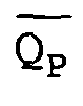
capacitor 49 to theelectrode output 50. Athird FET 56 is connected between thecapacitor 49 and ground and controlled at its gate by input
- For more detailed explanation of the circuitry, reference should be made to U.S. Patents 4,459,989 and 4,612,934 both to Borkan, incorporated herein by reference.
- Although the present stimulator system has been designed to allow the capability of providing individually designed stimulation pulses for each of the electrodes, the system could operate as a conventional neurostimulator system using delivery of a common stimulation pulse to select electrodes.
- As illustrated in Figure 6, a
stimulation lead 60 includes asheath 62 having a plurality of in-line electrodes 64 mutually spaced by a distance D1 and anadditional electrode 65 on asheath wire extension 67 extending from thedistal end 66. Theproximal end 68 hascontacts 69 connected to each electrode and to the stimulator outputs 50. Theadditional electrode 65 has a greater surface area on the sheath/wire than the surface area on the sheath of each of theelectrodes 64. - The
electrodes 64 all may have a length L1 and theadditional electrode 65 has a length L2. Length L2 is greater than L1, at least twice its length. Thus, for example, if length L1 is 2 mm, the length L2 is 4 mm. The length L2 may be anywhere between 2-4 times that of the length L1. Also, theadditional electrode 65 may have a greater circumferential dimension than each of theelectrodes 64. Theadditional electrode 65 may have a 360° circumference and theelectrodes 64 be 180° or less, for example. - Also, it should be noted that the
additional electrode 65 is spaced by a distance D2 from thenearest electrode 64. Where D1 is approximately 6 mm, the distance D2 is at least 10 mm and can be as much as 20 mm or more. With this distance, theelectrodes 64 each acts as a point source when used in conjunction with theadditional electrode 65 of the increased area. - Although a specific electrode is illustrated in Figure 6, other electrodes may be used with the stimulator system of the present invention. This is an example of an electrode which is capable of simultaneous operation in a bipolar mode and a monopolar mode as well as each mode alone. In the bipolar mode, at least two of the
electrodes 64 are used while in the monopolar mode, theadditional electrode 65 is used as an anode with at least one of theelectrodes 64 as a cathode. The individual programming of the stimulation pulse allows this to occur. - These stimulation paradigms could include sophisticated programs that switch stimulation between a number of electrodes slowly (over seconds or minutes, hours or days) to avoid accommodation of the stimulation or to treat multiple neural targets, or could be fast (approximately the same speed of the electrical activity of neurons in the spinal cord) artificially generating neural signals along the spinal cord or a nerve which could be perceived as any other sensory function with signals that travel through the spinal cord or nerve. For instance, a signal could be generated that would correspond to heat being applied to a patient's big toe, or pressure being applied to a patient's foot, or the sensation of a limb in a different orientation than it actually is.
- Theoretically, tastes, smells, sights or even thoughts could be created in this manner allowing various artificial prosthesis (visual, auditory, etc.) to interface with the human body.
- Although the present invention has been described and illustrated in detail, it is to be clearly understood that the same is by way of illustration and example only, and is not to be taken by way of limitation.
Claims (18)
- A tissue stimulation system comprising:an electrode assembly (60) having at least three electrodes (64) to be stimulated in a patient,a programmable stimulator (10) connected to and providing stimulation pulses to the electrode assembly (60), andprogramming data (22) in the stimulator (10) defining, for each of the at least three electrodes (64), individual stimulation pulses of varying polarity and at least one of amplitude, frequency, pulse width and pulse shape,characterised in thatthe stimulator (10) includes:a separate variable impedance circuit (46) for each electrode (64), anda common pulse generator (30) to provide a common stimulation voltage pulse to each of the variable impedance circuits (46), andthe stimulator (10) individually modifies the amplitude and pulse width of the common stimulation voltage pulse to each electrode (64).
- The system of claim 1, wherein the variable impedance circuit (46) includes a voltage divider for each electrode (64).
- The system of claim 1, wherein the variable impedance circuit (46) includes an analog switch for each electrode (64).
- The system of claim 1, wherein the stimulator (10) measures the series impedance of each of the electrodes (64) and modifies the stimulation pulse for each electrode (64) defined by the programming data as a function of the measured impedance of that electrode (64).
- The system of claim 1, wherein the stimulator (10) measures physical parameters and modifies the stimulation pulse for each electrode (64) defined by the programming data as a function of the measured parameters.
- The system of claim 1, including an additional electrode (65) spaced from the at least three electrodes (64), the additional electrode (65) having a greater surface area than each of the at least three electrodes (64).
- The system of claim 6, wherein the additional electrode (65) has at least twice the surface area of each of the at least three electrodes (64).
- The system of claim 6, wherein the additional electrode (65) is spaced from the at least three electrodes (64) by at least 10 mm.
- The system of claim 6, wherein the programming data (22) defines simultaneously stimulation in a bipolar mode using at least two of the at least three electrodes (64) and in a monopolar mode using the additional electrode (65) as an anode electrode and at least one of the at least three electrodes (64) as a cathode electrode.
- The system of claim 6, wherein the programming data (22) defines stimulation in a bipolar mode.
- The system of claim 6, wherein the programming data (22) defines stimulation in a monopolar mode using the additional electrode (65) as a common anode electrode with at least one of the at least three electrodes (64) as a cathode electrode.
- The system of claim 1, including a measurement circuit (26) to measure certain physiological parameters, and wherein the stimulator (10) modifies the stimulation pulses as a function of the measured parameters.
- The system of claim 12, wherein the measured parameters include one of the following: EMG, EKG, or EEG measurements.
- The system of claim 12, wherein the measurement circuit (26) includes chemical or biochemical sensors.
- The system of claim 12, wherein the stimulator (10) includes a signal input and modifies the stimulation pulses as a function of input signals on the signal input.
- The system of claim 15, wherein the input signals include processed audio or visual signals.
- The system of claim 12, wherein the stimulator (10) determines the position of the electrode (64) from the measured parameters and modifies the stimulation pulses as a function of the determined position.
- The system of claim 17, including a display (27) for showing the determined position.
Applications Claiming Priority (2)
| Application Number | Priority Date | Filing Date | Title |
|---|---|---|---|
| US22573100P | 2000-08-17 | 2000-08-17 | |
| US225731P | 2000-08-17 |
Publications (3)
| Publication Number | Publication Date |
|---|---|
| EP1181949A2 EP1181949A2 (en) | 2002-02-27 |
| EP1181949A3 EP1181949A3 (en) | 2002-09-18 |
| EP1181949B1 true EP1181949B1 (en) | 2006-10-18 |
Family
ID=22845993
Family Applications (1)
| Application Number | Title | Priority Date | Filing Date |
|---|---|---|---|
| EP01119556A Expired - Lifetime EP1181949B1 (en) | 2000-08-17 | 2001-08-14 | Multichannel stimulator electronics |
Country Status (5)
| Country | Link |
|---|---|
| US (1) | US6662053B2 (en) |
| EP (1) | EP1181949B1 (en) |
| AT (1) | ATE342750T1 (en) |
| DE (1) | DE60123889T2 (en) |
| ES (1) | ES2273767T3 (en) |
Families Citing this family (162)
| Publication number | Priority date | Publication date | Assignee | Title |
|---|---|---|---|---|
| US6587719B1 (en) | 1999-07-01 | 2003-07-01 | Cyberonics, Inc. | Treatment of obesity by bilateral vagus nerve stimulation |
| US6609025B2 (en) | 2001-01-02 | 2003-08-19 | Cyberonics, Inc. | Treatment of obesity by bilateral sub-diaphragmatic nerve stimulation |
| US6622047B2 (en) * | 2001-07-28 | 2003-09-16 | Cyberonics, Inc. | Treatment of neuropsychiatric disorders by near-diaphragmatic nerve stimulation |
| US6622038B2 (en) * | 2001-07-28 | 2003-09-16 | Cyberonics, Inc. | Treatment of movement disorders by near-diaphragmatic nerve stimulation |
| US6993384B2 (en) * | 2001-12-04 | 2006-01-31 | Advanced Bionics Corporation | Apparatus and method for determining the relative position and orientation of neurostimulation leads |
| US7853330B2 (en) * | 2001-12-04 | 2010-12-14 | Boston Scientific Neuromodulation Corporation | Apparatus and method for determining the relative position and orientation of neurostimulation leads |
| US7317948B1 (en) | 2002-02-12 | 2008-01-08 | Boston Scientific Scimed, Inc. | Neural stimulation system providing auto adjustment of stimulus output as a function of sensed impedance |
| US7239920B1 (en) | 2002-02-12 | 2007-07-03 | Advanced Bionics Corporation | Neural stimulation system providing auto adjustment of stimulus output as a function of sensed pressure changes |
| US20030153959A1 (en) * | 2002-02-12 | 2003-08-14 | Thacker James R. | Neural stimulation system providing auto adjustment of stimulus output as a function of sensed coupling efficiency |
| US7483748B2 (en) * | 2002-04-26 | 2009-01-27 | Medtronic, Inc. | Programmable waveform pulses for an implantable medical device |
| US6950706B2 (en) * | 2002-04-26 | 2005-09-27 | Medtronic, Inc. | Wave shaping for an implantable medical device |
| CA2493556C (en) | 2002-07-25 | 2012-04-03 | Thomas L. Ii Buchman | Electrosurgical pencil with drag sensing capability |
| US7244257B2 (en) | 2002-11-05 | 2007-07-17 | Sherwood Services Ag | Electrosurgical pencil having a single button variable control |
| WO2004073753A2 (en) | 2003-02-20 | 2004-09-02 | Sherwood Services Ag | Motion detector for controlling electrosurgical output |
| ITMO20030089A1 (en) | 2003-03-28 | 2004-09-29 | Lorenz Biotech Spa | ELECTROSTIMULATOR SYSTEM. |
| US7266412B2 (en) * | 2003-04-22 | 2007-09-04 | Medtronic, Inc. | Generation of multiple neurostimulation therapy programs |
| US8682423B2 (en) * | 2003-07-11 | 2014-03-25 | Ob Tools Ltd. | Three-dimensional monitoring of myographic activity |
| US7447542B2 (en) * | 2003-07-11 | 2008-11-04 | Ob Tools Ltd. | Three-dimensional monitoring of myographic activity |
| US7156842B2 (en) | 2003-11-20 | 2007-01-02 | Sherwood Services Ag | Electrosurgical pencil with improved controls |
| US7503917B2 (en) * | 2003-11-20 | 2009-03-17 | Covidien Ag | Electrosurgical pencil with improved controls |
| US7879033B2 (en) | 2003-11-20 | 2011-02-01 | Covidien Ag | Electrosurgical pencil with advanced ES controls |
| US20050283202A1 (en) * | 2004-06-22 | 2005-12-22 | Gellman Barry N | Neuromodulation system |
| US7346382B2 (en) | 2004-07-07 | 2008-03-18 | The Cleveland Clinic Foundation | Brain stimulation models, systems, devices, and methods |
| US8788044B2 (en) | 2005-01-21 | 2014-07-22 | Michael Sasha John | Systems and methods for tissue stimulation in medical treatment |
| US7571004B2 (en) * | 2005-01-26 | 2009-08-04 | Second Sight Medical Products, Inc. | Neural stimulation for increased persistence |
| US8260426B2 (en) | 2008-01-25 | 2012-09-04 | Cyberonics, Inc. | Method, apparatus and system for bipolar charge utilization during stimulation by an implantable medical device |
| US9314633B2 (en) | 2008-01-25 | 2016-04-19 | Cyberonics, Inc. | Contingent cardio-protection for epilepsy patients |
| US8565867B2 (en) | 2005-01-28 | 2013-10-22 | Cyberonics, Inc. | Changeable electrode polarity stimulation by an implantable medical device |
| US7920915B2 (en) * | 2005-11-16 | 2011-04-05 | Boston Scientific Neuromodulation Corporation | Implantable stimulator |
| US8401665B2 (en) * | 2005-04-01 | 2013-03-19 | Boston Scientific Neuromodulation Corporation | Apparatus and methods for detecting position and migration of neurostimulation leads |
| US9339650B2 (en) | 2005-04-13 | 2016-05-17 | The Cleveland Clinic Foundation | Systems and methods for neuromodulation using pre-recorded waveforms |
| US8112154B2 (en) * | 2005-04-13 | 2012-02-07 | The Cleveland Clinic Foundation | Systems and methods for neuromodulation using pre-recorded waveforms |
| US7979119B2 (en) * | 2005-04-26 | 2011-07-12 | Boston Scientific Neuromodulation Corporation | Display graphics for use in stimulation therapies |
| US7835796B2 (en) * | 2005-04-29 | 2010-11-16 | Cyberonics, Inc. | Weight loss method and device |
| US7310557B2 (en) * | 2005-04-29 | 2007-12-18 | Maschino Steven E | Identification of electrodes for nerve stimulation in the treatment of eating disorders |
| US7899540B2 (en) * | 2005-04-29 | 2011-03-01 | Cyberonics, Inc. | Noninvasively adjustable gastric band |
| US7500974B2 (en) | 2005-06-28 | 2009-03-10 | Covidien Ag | Electrode with rotatably deployable sheath |
| US7856273B2 (en) | 2005-07-28 | 2010-12-21 | Cyberonics, Inc. | Autonomic nerve stimulation to treat a gastrointestinal disorder |
| US7828794B2 (en) | 2005-08-25 | 2010-11-09 | Covidien Ag | Handheld electrosurgical apparatus for controlling operating room equipment |
| US7489561B2 (en) | 2005-10-24 | 2009-02-10 | Cyberonics, Inc. | Implantable medical device with reconfigurable non-volatile program |
| US20070100408A1 (en) * | 2005-10-28 | 2007-05-03 | Medtronic, Inc. | Electrical stimulation lead with proximal common electrode |
| US7996079B2 (en) | 2006-01-24 | 2011-08-09 | Cyberonics, Inc. | Input response override for an implantable medical device |
| US7769455B2 (en) * | 2006-01-27 | 2010-08-03 | Cyberonics, Inc. | Power supply monitoring for an implantable device |
| EP2965781B1 (en) | 2006-03-29 | 2019-06-05 | Dignity Health | Synchronization of vagus nerve stimulation with the cardiac cycle of a patient |
| US8180462B2 (en) | 2006-04-18 | 2012-05-15 | Cyberonics, Inc. | Heat dissipation for a lead assembly |
| US7962220B2 (en) | 2006-04-28 | 2011-06-14 | Cyberonics, Inc. | Compensation reduction in tissue stimulation therapy |
| US7869885B2 (en) | 2006-04-28 | 2011-01-11 | Cyberonics, Inc | Threshold optimization for tissue stimulation therapy |
| US20070260240A1 (en) | 2006-05-05 | 2007-11-08 | Sherwood Services Ag | Soft tissue RF transection and resection device |
| US8478420B2 (en) | 2006-07-12 | 2013-07-02 | Cyberonics, Inc. | Implantable medical device charge balance assessment |
| US20080027524A1 (en) | 2006-07-26 | 2008-01-31 | Maschino Steven E | Multi-electrode assembly for an implantable medical device |
| US7869867B2 (en) | 2006-10-27 | 2011-01-11 | Cyberonics, Inc. | Implantable neurostimulator with refractory stimulation |
| US7974707B2 (en) | 2007-01-26 | 2011-07-05 | Cyberonics, Inc. | Electrode assembly with fibers for a medical device |
| US7962214B2 (en) | 2007-04-26 | 2011-06-14 | Cyberonics, Inc. | Non-surgical device and methods for trans-esophageal vagus nerve stimulation |
| US7904175B2 (en) | 2007-04-26 | 2011-03-08 | Cyberonics, Inc. | Trans-esophageal vagus nerve stimulation |
| US7869884B2 (en) | 2007-04-26 | 2011-01-11 | Cyberonics, Inc. | Non-surgical device and methods for trans-esophageal vagus nerve stimulation |
| US7974701B2 (en) | 2007-04-27 | 2011-07-05 | Cyberonics, Inc. | Dosing limitation for an implantable medical device |
| US7769463B2 (en) * | 2007-06-19 | 2010-08-03 | Kalaco Scientific, Inc. | Multi-channel electrostimulation apparatus and method |
| JP2010534114A (en) * | 2007-07-20 | 2010-11-04 | ボストン サイエンティフィック ニューロモデュレイション コーポレイション | Use of stimulation pulse shapes to control nerve recovery commands and clinical effects |
| EP2183019A4 (en) * | 2007-08-06 | 2012-12-12 | Great Lakes Biosciences Llc | Methods and apparatus for electrical stimulation of tissues using signals that minimize the effects of tissue impedance |
| US8506565B2 (en) | 2007-08-23 | 2013-08-13 | Covidien Lp | Electrosurgical device with LED adapter |
| US8260425B2 (en) | 2007-10-12 | 2012-09-04 | Intelect Medical, Inc. | Deep brain stimulation system with inputs |
| US8812123B2 (en) * | 2007-10-17 | 2014-08-19 | Intelect Medical, Inc. | Patient programmer with input and sensing capabilities |
| US8942798B2 (en) | 2007-10-26 | 2015-01-27 | Cyberonics, Inc. | Alternative operation mode for an implantable medical device based upon lead condition |
| US8868203B2 (en) | 2007-10-26 | 2014-10-21 | Cyberonics, Inc. | Dynamic lead condition detection for an implantable medical device |
| US8235987B2 (en) | 2007-12-05 | 2012-08-07 | Tyco Healthcare Group Lp | Thermal penetration and arc length controllable electrosurgical pencil |
| CA2747264A1 (en) * | 2008-01-30 | 2009-08-06 | Great Lakes Biosciences, Llc | Brain-related chronic pain disorder treatment method and apparatus |
| US9220889B2 (en) | 2008-02-11 | 2015-12-29 | Intelect Medical, Inc. | Directional electrode devices with locating features |
| US8019440B2 (en) | 2008-02-12 | 2011-09-13 | Intelect Medical, Inc. | Directional lead assembly |
| US8597292B2 (en) | 2008-03-31 | 2013-12-03 | Covidien Lp | Electrosurgical pencil including improved controls |
| US8636733B2 (en) | 2008-03-31 | 2014-01-28 | Covidien Lp | Electrosurgical pencil including improved controls |
| US8632536B2 (en) | 2008-03-31 | 2014-01-21 | Covidien Lp | Electrosurgical pencil including improved controls |
| US8204603B2 (en) | 2008-04-25 | 2012-06-19 | Cyberonics, Inc. | Blocking exogenous action potentials by an implantable medical device |
| US9272153B2 (en) | 2008-05-15 | 2016-03-01 | Boston Scientific Neuromodulation Corporation | VOA generation system and method using a fiber specific analysis |
| US8162937B2 (en) | 2008-06-27 | 2012-04-24 | Tyco Healthcare Group Lp | High volume fluid seal for electrosurgical handpiece |
| US8155750B2 (en) * | 2008-07-24 | 2012-04-10 | Boston Scientific Neuromodulation Corporation | System and method for avoiding, reversing, and managing neurological accommodation to electrical stimulation |
| US9421359B2 (en) * | 2008-10-15 | 2016-08-23 | Medtronic Bakken Research Center B.V. | Probe for implantable electro-stimulation device |
| US8457747B2 (en) | 2008-10-20 | 2013-06-04 | Cyberonics, Inc. | Neurostimulation with signal duration determined by a cardiac cycle |
| US20100191304A1 (en) | 2009-01-23 | 2010-07-29 | Scott Timothy L | Implantable Medical Device for Providing Chronic Condition Therapy and Acute Condition Therapy Using Vagus Nerve Stimulation |
| US8231620B2 (en) | 2009-02-10 | 2012-07-31 | Tyco Healthcare Group Lp | Extension cutting blade |
| JP5734295B2 (en) | 2009-08-27 | 2015-06-17 | ザ クリーブランド クリニック ファウンデーション | System and method for estimating a site of tissue activity |
| WO2011068997A1 (en) | 2009-12-02 | 2011-06-09 | The Cleveland Clinic Foundation | Reversing cognitive-motor impairments in patients having a neuro-degenerative disease using a computational modeling approach to deep brain stimulation programming |
| US20110251817A1 (en) * | 2010-04-12 | 2011-10-13 | Reproductive Research Technologies, Llp | Method and apparatus to determine impedance variations in a skin/electrode interface |
| US8478428B2 (en) | 2010-04-23 | 2013-07-02 | Cyberonics, Inc. | Helical electrode for nerve stimulation |
| US8874229B2 (en) | 2010-04-28 | 2014-10-28 | Cyberonics, Inc. | Delivering scheduled and unscheduled therapy without detriment to battery life or accuracy of longevity predictions |
| CA2802708A1 (en) | 2010-06-14 | 2011-12-22 | Boston Scientific Neuromodulation Corporation | Programming interface for spinal cord neuromodulation |
| US9155891B2 (en) | 2010-09-20 | 2015-10-13 | Neuropace, Inc. | Current management system for a stimulation output stage of an implantable neurostimulation system |
| EP3219358A1 (en) * | 2010-10-13 | 2017-09-20 | Boston Scientific Neuromodulation Corporation | Architectures for an implantable medical device system having daisy-chained electrode-driver integrated circuits |
| US9101769B2 (en) | 2011-01-03 | 2015-08-11 | The Regents Of The University Of California | High density epidural stimulation for facilitation of locomotion, posture, voluntary movement, and recovery of autonomic, sexual, vasomotor, and cognitive function after neurological injury |
| AU2012207115B2 (en) | 2011-01-21 | 2016-03-10 | California Institute Of Technology | A parylene-based microelectrode array implant for spinal cord stimulation |
| US8577459B2 (en) | 2011-01-28 | 2013-11-05 | Cyberonics, Inc. | System and method for estimating battery capacity |
| BR112013024491A2 (en) | 2011-03-24 | 2017-03-21 | California Inst Of Techn | neurostimulator. |
| JP2014522247A (en) | 2011-03-29 | 2014-09-04 | ボストン サイエンティフィック ニューロモデュレイション コーポレイション | System and method for lead positioning |
| US8761884B2 (en) | 2011-04-14 | 2014-06-24 | Cyberonics, Inc. | Device longevity prediction for a device having variable energy consumption |
| US8761885B2 (en) | 2011-04-29 | 2014-06-24 | Cyberonics, Inc. | Battery life estimation based on voltage depletion rate |
| US9592389B2 (en) | 2011-05-27 | 2017-03-14 | Boston Scientific Neuromodulation Corporation | Visualization of relevant stimulation leadwire electrodes relative to selected stimulation information |
| US9925382B2 (en) | 2011-08-09 | 2018-03-27 | Boston Scientific Neuromodulation Corporation | Systems and methods for stimulation-related volume analysis, creation, and sharing |
| JP2014533183A (en) | 2011-11-11 | 2014-12-11 | ニューロイネイブリング テクノロジーズ インコーポレイテッド | Non-invasive neuromodulator to enable motor nerve, sensory, autonomy, sexual, vasomotor and cognitive recovery |
| US10092750B2 (en) | 2011-11-11 | 2018-10-09 | Neuroenabling Technologies, Inc. | Transcutaneous neuromodulation system and methods of using same |
| US9415218B2 (en) | 2011-11-11 | 2016-08-16 | The Regents Of The University Of California | Transcutaneous spinal cord stimulation: noninvasive tool for activation of locomotor circuitry |
| US10076383B2 (en) | 2012-01-25 | 2018-09-18 | Covidien Lp | Electrosurgical device having a multiplexer |
| EP2819745B1 (en) | 2012-02-29 | 2018-10-10 | The Cleveland Clinic Foundation | System and method for generating composite patterns of stimulation or waveforms |
| US9037236B2 (en) | 2012-06-29 | 2015-05-19 | Pacesetter, Inc. | Method and system to select a neurostimulation system configuration based on cardiac rhythm feedback |
| WO2014025624A1 (en) | 2012-08-04 | 2014-02-13 | Boston Scientific Neuromodulation Corporation | Techniques and methods for storing and transferring registration, atlas, and lead information between medical devices |
| AU2013308906B2 (en) | 2012-08-28 | 2016-07-21 | Boston Scientific Neuromodulation Corporation | Point-and-click programming for deep brain stimulation using real-time monopolar review trendlines |
| WO2014070290A2 (en) | 2012-11-01 | 2014-05-08 | Boston Scientific Neuromodulation Corporation | Systems and methods for voa model generation and use |
| CA2906779C (en) | 2013-03-15 | 2022-08-30 | The Regents Of The University Of California | Multi-site transcutaneous electrical stimulation of the spinal cord for facilitation of locomotion |
| US9872997B2 (en) | 2013-03-15 | 2018-01-23 | Globus Medical, Inc. | Spinal cord stimulator system |
| US9440076B2 (en) | 2013-03-15 | 2016-09-13 | Globus Medical, Inc. | Spinal cord stimulator system |
| US9878170B2 (en) | 2013-03-15 | 2018-01-30 | Globus Medical, Inc. | Spinal cord stimulator system |
| US9887574B2 (en) | 2013-03-15 | 2018-02-06 | Globus Medical, Inc. | Spinal cord stimulator system |
| AU2014324660A1 (en) | 2013-09-27 | 2016-04-21 | The Regents Of The University Of California | Engaging the cervical spinal cord circuitry to re-enable volitional control of hand function in tetraplegic subjects |
| US20150217120A1 (en) | 2014-01-13 | 2015-08-06 | Mandheerej Nandra | Neuromodulation systems and methods of using same |
| WO2016004230A1 (en) | 2014-07-03 | 2016-01-07 | Boston Scientific Neuromodulation Corporation | Neurostimulation system with flexible patterning and waveforms |
| US9959388B2 (en) | 2014-07-24 | 2018-05-01 | Boston Scientific Neuromodulation Corporation | Systems, devices, and methods for providing electrical stimulation therapy feedback |
| US10272247B2 (en) | 2014-07-30 | 2019-04-30 | Boston Scientific Neuromodulation Corporation | Systems and methods for stimulation-related volume analysis, creation, and sharing with integrated surgical planning and stimulation programming |
| US10265528B2 (en) | 2014-07-30 | 2019-04-23 | Boston Scientific Neuromodulation Corporation | Systems and methods for electrical stimulation-related patient population volume analysis and use |
| JP2016036624A (en) * | 2014-08-08 | 2016-03-22 | オリンパス株式会社 | Nerve stimulation device |
| AU2015301401B2 (en) | 2014-08-15 | 2020-01-16 | Axonics Modulation Technologies, Inc. | Electromyographic lead positioning and stimulation titration in a nerve stimulation system for treatment of overactive bladder |
| US10092762B2 (en) | 2014-08-15 | 2018-10-09 | Axonics Modulation Technologies, Inc. | Integrated electromyographic clinician programmer for use with an implantable neurostimulator |
| CA2957967C (en) | 2014-08-15 | 2018-11-27 | Axonics Modulation Technologies, Inc. | Systems and methods for neurostimulation electrode configurations based on neural localization |
| US10751533B2 (en) | 2014-08-21 | 2020-08-25 | The Regents Of The University Of California | Regulation of autonomic control of bladder voiding after a complete spinal cord injury |
| AU2015308779B2 (en) | 2014-08-27 | 2020-06-25 | The Regents Of The University Of California | Multi-electrode array for spinal cord epidural stimulation |
| US9974959B2 (en) | 2014-10-07 | 2018-05-22 | Boston Scientific Neuromodulation Corporation | Systems, devices, and methods for electrical stimulation using feedback to adjust stimulation parameters |
| CA2983582A1 (en) | 2015-03-20 | 2016-09-29 | Ricardo Vallejo | Method and apparatus for multimodal electrical modulation of pain |
| US11167139B2 (en) | 2015-03-20 | 2021-11-09 | Medtronic Sg, Llc | Method and apparatus for multi modal electrical modulation of pain using composite electromagnetic fields |
| US10850102B2 (en) | 2015-03-20 | 2020-12-01 | Medtronic Sg, Llc | Method and apparatus for multimodal electrical modulation of pain |
| US10780283B2 (en) | 2015-05-26 | 2020-09-22 | Boston Scientific Neuromodulation Corporation | Systems and methods for analyzing electrical stimulation and selecting or manipulating volumes of activation |
| US9956419B2 (en) | 2015-05-26 | 2018-05-01 | Boston Scientific Neuromodulation Corporation | Systems and methods for analyzing electrical stimulation and selecting or manipulating volumes of activation |
| WO2017003946A1 (en) | 2015-06-29 | 2017-01-05 | Boston Scientific Neuromodulation Corporation | Systems and methods for selecting stimulation parameters based on stimulation target region, effects, or side effects |
| US10441800B2 (en) | 2015-06-29 | 2019-10-15 | Boston Scientific Neuromodulation Corporation | Systems and methods for selecting stimulation parameters by targeting and steering |
| US11298533B2 (en) | 2015-08-26 | 2022-04-12 | The Regents Of The University Of California | Concerted use of noninvasive neuromodulation device with exoskeleton to enable voluntary movement and greater muscle activation when stepping in a chronically paralyzed subject |
| US10300282B2 (en) * | 2015-09-18 | 2019-05-28 | Medtronic, Inc. | Electrical stimulation therapy for inducing patient sensations |
| US10675468B2 (en) * | 2015-09-18 | 2020-06-09 | Medtronic, Inc. | Electrical stimulation therapy for inducing patient sensations |
| WO2017062378A1 (en) | 2015-10-09 | 2017-04-13 | Boston Scientific Neuromodulation Corporation | System and methods for clinical effects mapping for directional stimulations leads |
| US11097122B2 (en) | 2015-11-04 | 2021-08-24 | The Regents Of The University Of California | Magnetic stimulation of the spinal cord to restore control of bladder and/or bowel |
| WO2017158067A1 (en) * | 2016-03-15 | 2017-09-21 | Universität Bern | Method and system for optimisation of dbs programming |
| US10716942B2 (en) | 2016-04-25 | 2020-07-21 | Boston Scientific Neuromodulation Corporation | System and methods for directional steering of electrical stimulation |
| CN109416937A (en) | 2016-06-24 | 2019-03-01 | 波士顿科学神经调制公司 | The system and method for visual analysis for clinical effectiveness |
| US10350404B2 (en) | 2016-09-02 | 2019-07-16 | Boston Scientific Neuromodulation Corporation | Systems and methods for visualizing and directing stimulation of neural elements |
| US10780282B2 (en) | 2016-09-20 | 2020-09-22 | Boston Scientific Neuromodulation Corporation | Systems and methods for steering electrical stimulation of patient tissue and determining stimulation parameters |
| AU2017341910B2 (en) | 2016-10-14 | 2020-05-14 | Boston Scientific Neuromodulation Corporation | Systems and methods for closed-loop determination of stimulation parameter settings for an electrical simulation system |
| AU2017391436B2 (en) | 2017-01-03 | 2020-06-18 | Boston Scientific Neuromodulation Corporation | Systems and methods for selecting MRI-compatible stimulation parameters |
| US10589104B2 (en) | 2017-01-10 | 2020-03-17 | Boston Scientific Neuromodulation Corporation | Systems and methods for creating stimulation programs based on user-defined areas or volumes |
| US10625082B2 (en) | 2017-03-15 | 2020-04-21 | Boston Scientific Neuromodulation Corporation | Visualization of deep brain stimulation efficacy |
| WO2018187090A1 (en) | 2017-04-03 | 2018-10-11 | Boston Scientific Neuromodulation Corporation | Systems and methods for estimating a volume of activation using a compressed database of threshold values |
| EP3421081B1 (en) | 2017-06-30 | 2020-04-15 | GTX medical B.V. | A system for neuromodulation |
| EP3651849B1 (en) | 2017-07-14 | 2023-05-31 | Boston Scientific Neuromodulation Corporation | Estimating clinical effects of electrical stimulation |
| EP3634569A1 (en) | 2017-08-15 | 2020-04-15 | Boston Scientific Neuromodulation Corporation | Systems and methods for controlling electrical stimulation using multiple stimulation fields |
| US11992684B2 (en) | 2017-12-05 | 2024-05-28 | Ecole Polytechnique Federale De Lausanne (Epfl) | System for planning and/or providing neuromodulation |
| WO2019147679A1 (en) * | 2018-01-23 | 2019-08-01 | Mayo Foundation For Medical Education And Research | Epidural stimulation and spinal structure locating techniques |
| WO2019210214A1 (en) | 2018-04-27 | 2019-10-31 | Boston Scientific Neuromodulation Corporation | Systems for visualizing and programming electrical stimulation |
| EP3784331B1 (en) | 2018-04-27 | 2023-01-18 | Boston Scientific Neuromodulation Corporation | Multi-mode electrical stimulation systems and methods of making and using |
| US11566885B2 (en) | 2018-10-31 | 2023-01-31 | Biotronik Se & Co. Kg | Method for relative lead offset determination |
| DE18205821T1 (en) | 2018-11-13 | 2020-12-24 | Gtx Medical B.V. | CONTROL SYSTEM FOR MOTION RECONSTRUCTION AND / OR RECOVERY FOR A PATIENT |
| EP3653260A1 (en) | 2018-11-13 | 2020-05-20 | GTX medical B.V. | Sensor in clothing of limbs or footwear |
| EP3695878B1 (en) | 2019-02-12 | 2023-04-19 | ONWARD Medical N.V. | A system for neuromodulation |
| US11918811B2 (en) | 2019-05-06 | 2024-03-05 | Medtronic Sg, Llc | Method and apparatus for multi modal or multiplexed electrical modulation of pain using composite electromagnetic fields |
| US11848090B2 (en) | 2019-05-24 | 2023-12-19 | Axonics, Inc. | Trainer for a neurostimulator programmer and associated methods of use with a neurostimulation system |
| US11439829B2 (en) | 2019-05-24 | 2022-09-13 | Axonics, Inc. | Clinician programmer methods and systems for maintaining target operating temperatures |
| DE19211698T1 (en) | 2019-11-27 | 2021-09-02 | Onward Medical B.V. | Neuromodulation system |
| US11564732B2 (en) | 2019-12-05 | 2023-01-31 | Covidien Lp | Tensioning mechanism for bipolar pencil |
| US20230264031A1 (en) * | 2020-08-06 | 2023-08-24 | Affera, Inc. | Systems for tissue stimulation and associated methods |
Family Cites Families (13)
| Publication number | Priority date | Publication date | Assignee | Title |
|---|---|---|---|---|
| US3449768A (en) | 1966-12-27 | 1969-06-17 | James H Doyle | Artificial sense organ |
| US3727616A (en) | 1971-06-15 | 1973-04-17 | Gen Dynamics Corp | Electronic system for the stimulation of biological systems |
| US4379462A (en) | 1980-10-29 | 1983-04-12 | Neuromed, Inc. | Multi-electrode catheter assembly for spinal cord stimulation |
| US4459989A (en) * | 1981-06-30 | 1984-07-17 | Neuromed, Inc. | Non-invasive multiprogrammable tissue stimulator and methods for use |
| US4612934A (en) * | 1981-06-30 | 1986-09-23 | Borkan William N | Non-invasive multiprogrammable tissue stimulator |
| US4793353A (en) * | 1981-06-30 | 1988-12-27 | Borkan William N | Non-invasive multiprogrammable tissue stimulator and method |
| US4935345A (en) | 1987-04-07 | 1990-06-19 | Arizona Board Of Regents | Implantable microelectronic biochemical sensor incorporating thin film thermopile |
| US5649970A (en) | 1995-08-18 | 1997-07-22 | Loeb; Gerald E. | Edge-effect electrodes for inducing spatially controlled distributions of electrical potentials in volume conductive media |
| US5702429A (en) | 1996-04-04 | 1997-12-30 | Medtronic, Inc. | Neural stimulation techniques with feedback |
| US5938690A (en) | 1996-06-07 | 1999-08-17 | Advanced Neuromodulation Systems, Inc. | Pain management system and method |
| US5895416A (en) | 1997-03-12 | 1999-04-20 | Medtronic, Inc. | Method and apparatus for controlling and steering an electric field |
| US5941906A (en) | 1997-10-15 | 1999-08-24 | Medtronic, Inc. | Implantable, modular tissue stimulator |
| US6052624A (en) | 1999-01-07 | 2000-04-18 | Advanced Bionics Corporation | Directional programming for implantable electrode arrays |
-
2001
- 2001-04-19 US US09/837,652 patent/US6662053B2/en not_active Expired - Fee Related
- 2001-08-14 ES ES01119556T patent/ES2273767T3/en not_active Expired - Lifetime
- 2001-08-14 DE DE60123889T patent/DE60123889T2/en not_active Expired - Lifetime
- 2001-08-14 AT AT01119556T patent/ATE342750T1/en not_active IP Right Cessation
- 2001-08-14 EP EP01119556A patent/EP1181949B1/en not_active Expired - Lifetime
Also Published As
| Publication number | Publication date |
|---|---|
| ATE342750T1 (en) | 2006-11-15 |
| DE60123889D1 (en) | 2006-11-30 |
| EP1181949A2 (en) | 2002-02-27 |
| US6662053B2 (en) | 2003-12-09 |
| EP1181949A3 (en) | 2002-09-18 |
| DE60123889T2 (en) | 2007-06-06 |
| ES2273767T3 (en) | 2007-05-16 |
| US20020022866A1 (en) | 2002-02-21 |
Similar Documents
| Publication | Publication Date | Title |
|---|---|---|
| EP1181949B1 (en) | Multichannel stimulator electronics | |
| US11471670B2 (en) | Electrical stimulator for treatment of back pain and methods of use | |
| JP5188494B2 (en) | System and method using multiple timing channels for electrode adjustment during implant stimulator setup | |
| AU2007207297B2 (en) | Method of routing electrical current to bodily tissues via implanted passive conductors | |
| US9072886B2 (en) | Method of routing electrical current to bodily tissues via implanted passive conductors | |
| CN116251294A (en) | Selective high frequency spinal cord modulation for pain inhibition with reduced side effects, and related systems and methods | |
| Davis | International Functional Electrical Stimulation Society (IFESS): the Development of Controlled Neural Prostheses for Functional Restoration | |
| AU2017293441B2 (en) | Systems and methods for restoring muscle function to the lumbar spine and kits for implanting same | |
| US20120290059A1 (en) | System and method for electrical modulation of the posterior longitudinal ligament | |
| US11684774B2 (en) | Electrical stimulator for treatment of back pain and methods of use | |
| US20230067424A1 (en) | Electrical stimulator for the treatment of back pain and methods of use | |
| WO2024025813A1 (en) | Determining location of medical lead during implantation |
Legal Events
| Date | Code | Title | Description |
|---|---|---|---|
| PUAI | Public reference made under article 153(3) epc to a published international application that has entered the european phase |
Free format text: ORIGINAL CODE: 0009012 |
|
| AK | Designated contracting states |
Kind code of ref document: A2 Designated state(s): AT BE CH CY DE DK ES FI FR GB GR IE IT LI LU MC NL PT SE TR |
|
| AX | Request for extension of the european patent |
Free format text: AL;LT;LV;MK;RO;SI |
|
| PUAL | Search report despatched |
Free format text: ORIGINAL CODE: 0009013 |
|
| AK | Designated contracting states |
Kind code of ref document: A3 Designated state(s): AT BE CH CY DE DK ES FI FR GB GR IE IT LI LU MC NL PT SE TR |
|
| AX | Request for extension of the european patent |
Free format text: AL;LT;LV;MK;RO;SI |
|
| RIC1 | Information provided on ipc code assigned before grant |
Free format text: 7A 61N 1/34 A, 7A 61N 1/372 B, 7A 61B 5/00 B |
|
| 17P | Request for examination filed |
Effective date: 20030305 |
|
| AKX | Designation fees paid |
Designated state(s): AT BE CH CY DE DK ES FI FR GB GR IE IT LI LU MC NL PT SE TR |
|
| 17Q | First examination report despatched |
Effective date: 20040614 |
|
| GRAP | Despatch of communication of intention to grant a patent |
Free format text: ORIGINAL CODE: EPIDOSNIGR1 |
|
| GRAS | Grant fee paid |
Free format text: ORIGINAL CODE: EPIDOSNIGR3 |
|
| GRAA | (expected) grant |
Free format text: ORIGINAL CODE: 0009210 |
|
| AK | Designated contracting states |
Kind code of ref document: B1 Designated state(s): AT BE CH CY DE DK ES FI FR GB GR IE IT LI LU MC NL PT SE TR |
|
| PG25 | Lapsed in a contracting state [announced via postgrant information from national office to epo] |
Ref country code: AT Free format text: LAPSE BECAUSE OF FAILURE TO SUBMIT A TRANSLATION OF THE DESCRIPTION OR TO PAY THE FEE WITHIN THE PRESCRIBED TIME-LIMIT Effective date: 20061018 Ref country code: IT Free format text: LAPSE BECAUSE OF FAILURE TO SUBMIT A TRANSLATION OF THE DESCRIPTION OR TO PAY THE FEE WITHIN THE PRESCRIBED TIME-LIMIT;WARNING: LAPSES OF ITALIAN PATENTS WITH EFFECTIVE DATE BEFORE 2007 MAY HAVE OCCURRED AT ANY TIME BEFORE 2007. THE CORRECT EFFECTIVE DATE MAY BE DIFFERENT FROM THE ONE RECORDED. Effective date: 20061018 Ref country code: CH Free format text: LAPSE BECAUSE OF FAILURE TO SUBMIT A TRANSLATION OF THE DESCRIPTION OR TO PAY THE FEE WITHIN THE PRESCRIBED TIME-LIMIT Effective date: 20061018 Ref country code: BE Free format text: LAPSE BECAUSE OF FAILURE TO SUBMIT A TRANSLATION OF THE DESCRIPTION OR TO PAY THE FEE WITHIN THE PRESCRIBED TIME-LIMIT Effective date: 20061018 Ref country code: NL Free format text: LAPSE BECAUSE OF FAILURE TO SUBMIT A TRANSLATION OF THE DESCRIPTION OR TO PAY THE FEE WITHIN THE PRESCRIBED TIME-LIMIT Effective date: 20061018 Ref country code: LI Free format text: LAPSE BECAUSE OF FAILURE TO SUBMIT A TRANSLATION OF THE DESCRIPTION OR TO PAY THE FEE WITHIN THE PRESCRIBED TIME-LIMIT Effective date: 20061018 Ref country code: FI Free format text: LAPSE BECAUSE OF FAILURE TO SUBMIT A TRANSLATION OF THE DESCRIPTION OR TO PAY THE FEE WITHIN THE PRESCRIBED TIME-LIMIT Effective date: 20061018 |
|
| REG | Reference to a national code |
Ref country code: GB Ref legal event code: FG4D |
|
| REG | Reference to a national code |
Ref country code: CH Ref legal event code: EP Ref country code: IE Ref legal event code: FG4D |
|
| REF | Corresponds to: |
Ref document number: 60123889 Country of ref document: DE Date of ref document: 20061130 Kind code of ref document: P |
|
| PG25 | Lapsed in a contracting state [announced via postgrant information from national office to epo] |
Ref country code: DK Free format text: LAPSE BECAUSE OF FAILURE TO SUBMIT A TRANSLATION OF THE DESCRIPTION OR TO PAY THE FEE WITHIN THE PRESCRIBED TIME-LIMIT Effective date: 20070118 Ref country code: SE Free format text: LAPSE BECAUSE OF FAILURE TO SUBMIT A TRANSLATION OF THE DESCRIPTION OR TO PAY THE FEE WITHIN THE PRESCRIBED TIME-LIMIT Effective date: 20070118 |
|
| PG25 | Lapsed in a contracting state [announced via postgrant information from national office to epo] |
Ref country code: PT Free format text: LAPSE BECAUSE OF FAILURE TO SUBMIT A TRANSLATION OF THE DESCRIPTION OR TO PAY THE FEE WITHIN THE PRESCRIBED TIME-LIMIT Effective date: 20070319 |
|
| NLV1 | Nl: lapsed or annulled due to failure to fulfill the requirements of art. 29p and 29m of the patents act | ||
| ET | Fr: translation filed | ||
| REG | Reference to a national code |
Ref country code: CH Ref legal event code: PL |
|
| REG | Reference to a national code |
Ref country code: ES Ref legal event code: FG2A Ref document number: 2273767 Country of ref document: ES Kind code of ref document: T3 |
|
| PLBE | No opposition filed within time limit |
Free format text: ORIGINAL CODE: 0009261 |
|
| STAA | Information on the status of an ep patent application or granted ep patent |
Free format text: STATUS: NO OPPOSITION FILED WITHIN TIME LIMIT |
|
| 26N | No opposition filed |
Effective date: 20070719 |
|
| PG25 | Lapsed in a contracting state [announced via postgrant information from national office to epo] |
Ref country code: MC Free format text: LAPSE BECAUSE OF NON-PAYMENT OF DUE FEES Effective date: 20070831 Ref country code: GR Free format text: LAPSE BECAUSE OF FAILURE TO SUBMIT A TRANSLATION OF THE DESCRIPTION OR TO PAY THE FEE WITHIN THE PRESCRIBED TIME-LIMIT Effective date: 20070119 |
|
| PG25 | Lapsed in a contracting state [announced via postgrant information from national office to epo] |
Ref country code: IE Free format text: LAPSE BECAUSE OF NON-PAYMENT OF DUE FEES Effective date: 20070814 |
|
| PG25 | Lapsed in a contracting state [announced via postgrant information from national office to epo] |
Ref country code: CY Free format text: LAPSE BECAUSE OF FAILURE TO SUBMIT A TRANSLATION OF THE DESCRIPTION OR TO PAY THE FEE WITHIN THE PRESCRIBED TIME-LIMIT Effective date: 20061018 Ref country code: LU Free format text: LAPSE BECAUSE OF NON-PAYMENT OF DUE FEES Effective date: 20070814 |
|
| PG25 | Lapsed in a contracting state [announced via postgrant information from national office to epo] |
Ref country code: TR Free format text: LAPSE BECAUSE OF FAILURE TO SUBMIT A TRANSLATION OF THE DESCRIPTION OR TO PAY THE FEE WITHIN THE PRESCRIBED TIME-LIMIT Effective date: 20061018 |
|
| PGFP | Annual fee paid to national office [announced via postgrant information from national office to epo] |
Ref country code: ES Payment date: 20090826 Year of fee payment: 9 Ref country code: FR Payment date: 20090817 Year of fee payment: 9 |
|
| PGFP | Annual fee paid to national office [announced via postgrant information from national office to epo] |
Ref country code: IT Payment date: 20090825 Year of fee payment: 9 |
|
| REG | Reference to a national code |
Ref country code: FR Ref legal event code: ST Effective date: 20110502 |
|
| PG25 | Lapsed in a contracting state [announced via postgrant information from national office to epo] |
Ref country code: IT Free format text: LAPSE BECAUSE OF NON-PAYMENT OF DUE FEES Effective date: 20100814 |
|
| PG25 | Lapsed in a contracting state [announced via postgrant information from national office to epo] |
Ref country code: FR Free format text: LAPSE BECAUSE OF NON-PAYMENT OF DUE FEES Effective date: 20100831 |
|
| REG | Reference to a national code |
Ref country code: ES Ref legal event code: FD2A Effective date: 20111019 |
|
| PG25 | Lapsed in a contracting state [announced via postgrant information from national office to epo] |
Ref country code: ES Free format text: LAPSE BECAUSE OF NON-PAYMENT OF DUE FEES Effective date: 20100815 |
|
| PGFP | Annual fee paid to national office [announced via postgrant information from national office to epo] |
Ref country code: DE Payment date: 20110830 Year of fee payment: 11 Ref country code: GB Payment date: 20110825 Year of fee payment: 11 |
|
| GBPC | Gb: european patent ceased through non-payment of renewal fee |
Effective date: 20120814 |
|
| PG25 | Lapsed in a contracting state [announced via postgrant information from national office to epo] |
Ref country code: GB Free format text: LAPSE BECAUSE OF NON-PAYMENT OF DUE FEES Effective date: 20120814 Ref country code: DE Free format text: LAPSE BECAUSE OF NON-PAYMENT OF DUE FEES Effective date: 20130301 |
|
| REG | Reference to a national code |
Ref country code: DE Ref legal event code: R119 Ref document number: 60123889 Country of ref document: DE Effective date: 20130301 |