EP1181860A2 - Gang type rotary lawn mower - Google Patents
Gang type rotary lawn mower Download PDFInfo
- Publication number
- EP1181860A2 EP1181860A2 EP01120134A EP01120134A EP1181860A2 EP 1181860 A2 EP1181860 A2 EP 1181860A2 EP 01120134 A EP01120134 A EP 01120134A EP 01120134 A EP01120134 A EP 01120134A EP 1181860 A2 EP1181860 A2 EP 1181860A2
- Authority
- EP
- European Patent Office
- Prior art keywords
- roller
- deck
- lawn mower
- frame
- assemblies
- Prior art date
- Legal status (The legal status is an assumption and is not a legal conclusion. Google has not performed a legal analysis and makes no representation as to the accuracy of the status listed.)
- Granted
Links
- 230000000712 assembly Effects 0.000 claims abstract description 57
- 238000000429 assembly Methods 0.000 claims abstract description 57
- 238000005096 rolling process Methods 0.000 claims description 14
- 244000025254 Cannabis sativa Species 0.000 description 9
- 238000010276 construction Methods 0.000 description 6
- 210000005069 ears Anatomy 0.000 description 4
- 238000009966 trimming Methods 0.000 description 3
- 230000003247 decreasing effect Effects 0.000 description 2
- 230000000694 effects Effects 0.000 description 2
- 239000012530 fluid Substances 0.000 description 2
- 238000012423 maintenance Methods 0.000 description 2
- 238000002485 combustion reaction Methods 0.000 description 1
- 238000004806 packaging method and process Methods 0.000 description 1
Images






Classifications
-
- A—HUMAN NECESSITIES
- A01—AGRICULTURE; FORESTRY; ANIMAL HUSBANDRY; HUNTING; TRAPPING; FISHING
- A01D—HARVESTING; MOWING
- A01D34/00—Mowers; Mowing apparatus of harvesters
- A01D34/01—Mowers; Mowing apparatus of harvesters characterised by features relating to the type of cutting apparatus
- A01D34/412—Mowers; Mowing apparatus of harvesters characterised by features relating to the type of cutting apparatus having rotating cutters
- A01D34/63—Mowers; Mowing apparatus of harvesters characterised by features relating to the type of cutting apparatus having rotating cutters having cutters rotating about a vertical axis
- A01D34/74—Cutting-height adjustment
-
- A—HUMAN NECESSITIES
- A01—AGRICULTURE; FORESTRY; ANIMAL HUSBANDRY; HUNTING; TRAPPING; FISHING
- A01D—HARVESTING; MOWING
- A01D75/00—Accessories for harvesters or mowers
- A01D75/30—Arrangements for trailing two or more mowers
Definitions
- the invention relates to rotary lawn mowers and to gang-type lawn mowers.
- reel mowers have been used to cut golf course roughs. It is generally recognized that rotary mowers are better suited for cutting tall grass, where scalping is not a problem, while reel mowers are better for shorter cutting.
- a gang of reels can be either attached directly to the frame on which the operator rides, or pulled behind a tractor. Pull-behind or tow-behind rotary gangs are also known. These can be driven either by a power takeoff or by a separate engine. Tow-behind gangs, whether reel or rotary, are generally undesirable for cutting a golf course rough because close trimming is difficult. Thus, rotary mowers have not been used to cut golf course roughs, which require close trimming and the ability to cut undulating terrain at a relatively short length.
- the invention provides a gang-type rotary lawn mower suitable for cutting a golf course rough. This is a tremendous improvement over the known prior art, because a rotary mower typically requires substantially less maintenance than a reel mower.
- the lawn mower has single-spindle cutting decks attached directly to the frame on which the operator rides, with a front row of two or more cutting decks in front of the front wheels, and with a rear row of one or more cutting decks between the front and rear wheels.
- the invention also provides an improved arrangement for mounting a rotary cutting deck on a lawn mower frame. Each deck is mounted on its own lifting arm so that the deck can move vertically relative to the frame and can pivot relative to the frame about three mutually perpendicular axes.
- the invention provides a gang-type rotary lawn mower comprising a frame supported by front and rear wheels, an operator's seat mounted on the frame, at least two side-by-side front cutting deck assemblies mounted on the frame in front of the front wheels, and at least one rear cutting deck assembly mounted on the frame behind the front wheels and in front of the rear wheels.
- Each of the front and rear deck assemblies includes a pair of laterally-spaced, generally vertically-extending side plates, front wheels supporting the side plates for movement over the ground, and a rear roller extending between the side plates and supporting the side plates for movement over the ground.
- Each deck assembly also includes a single-spindle cutting deck located between the side plates and in front of the roller, the deck being mounted on the side plates such that the height of the deck relative to the ground is adjustable.
- the roller extends across substantially the entire width of the deck. The roller resists scalping and stripes the grass, both of which are aesthetically desirable.
- Each deck assembly is connected to the frame by a generally L-shaped, horizontally-extending lifting arm operable to lift the deck assembly relative to the frame.
- Each deck assembly is connected to the frame by its own lifting arm.
- Each lifting arm has an inner end pivotally connected to the frame.
- a cross member is mounted on the outer end of the lifting arm for pivotal movement about a generally vertical axis and about a generally horizontal axis extending in the forward-rearward direction.
- One end of the cross member is connected to one of the deck assembly side plates for pivotal movement about a generally horizontal, laterally-extending axis adjacent the forward ends of the side plates, and the other end of the cross member is connected to the other side plate for pivotal movement about the same axis.
- This construction enables the lawn mower to cut the undulating terrain of a golf course rough and to be controlled for close trimming. Also, as mentioned above, the lawn mower requires much less maintenance than the reel mowers historically used to cut a golf course rough.
- FIG. 1 A lawn mower 10 embodying the invention is illustrated in FIG. 1. Except as described below, the lawn mower 10 is identical to the lawn mower disclosed in U.S. patent application Serial No. 08/787,384, filed Jan. 22, 1997, titled "PARALLEL-SERIES FOUR-WHEEL-DRIVE HYDRAULIC CIRCUIT FOR A RIDING LAWN MOWER" and assigned to the assignee hereof.
- the lawn mower 10 comprises a frame 12 (partially shown in FIGS. 2-5) supported by front wheels 14 and rear wheels 16 for movement over the ground. While the illustrated lawn mower 10 is rear-steering and has four-wheel drive, it should be understood that the invention is applicable to front-steering or two-wheel-drive lawn mowers.
- the lawn mower 10 further comprises a power source 18 supported by the frame 12.
- the power source may be any type known in the art, such as a gasoline-powered, internal-combustion engine.
- the engine drives a hydraulic pump (not shown) that supplies hydraulic fluid to hydraulic motors (not shown) drivingly connected to the wheels 14 and 16.
- the lawn mower 10 further comprises an operator's seat 20, and a conventional steering system, including a steering wheel 22, enabling the operator to steer the lawn mower 10.
- the steering system is hydraulic and is connected to the rear wheels 16 to steer the lawn mower 10.
- the lawn mower 10 further comprises front and rear rows 26 and 30, respectively, of cutting deck assemblies 34. More particularly, in the illustrated construction, the lawn mower 10 has three side-by-side front cutting deck assemblies 34 in front of the front wheels 14, and two rear cutting deck assemblies 34 behind the front wheels 14 and in front of the rear wheels 16. As is known in the art, each rear deck assembly 34 is aligned with the gap between two adjacent front deck assemblies 34.
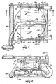
- Each of the cutting deck assemblies 34 includes (see FIGS. 2-5) a single-spindle mulching deck 38 defining a downwardly opening space 42 (FIG. 4).
- the deck 38 is located between and supported by a pair of laterally-spaced, generally vertically-extending side plates 46 and 48.
- the term "lateral” is used herein to mean the direction from one side of the lawn mower to the other, i.e., perpendicular to the forward-rearward direction.
- Two front wheels 50 rotate about an axle 54 (FIGS. 2 and 3) extending between the side plates 46 and 48 in front of the deck 38, such that each front wheel 50 supports one of the side plates 46 and 48 and the deck 38 for movement over the ground.
- a rear roller 58 extends between the side plates 46 and 48 and also supports the side plates 46 and 48 and the deck 38 for movement over the ground.
- the roller 58 is behind the deck 38 and extends across substantially the entire width of the deck 38. The roller 58 resists scalping and stripes the grass.
- the deck 38 is mounted on the side plates 46 and 48 such that the height of the deck 38 relative to the ground is adjustable.
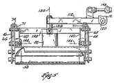
- the deck 38 includes spaced deck plates 66 and 68 (FIGS. 3 and 5) extending upwardly adjacent the side plates 46 and 48, respectively.
- the upper end of each side plate 46 or 48 has thereon (see FIG. 2) generally horizontal, inwardly-extending ears 69 and 70, with the ear 69 adjacent the front of the side plate and the ear 70 adjacent the rear of the side plate.
- Fixed to the ears 69 and 70 of each side plate 46 or 48 is an elongated plate member 71 having outwardly-extending ears 72 and 73 respectively secured to the ears 69 and 70 by suitable means such as bolts or screws 74.
- Each side plate 46 or 48 and the corresponding plate member 71 has therein (see FIGS. 4 and 6) a series of holes 76.
- Each of the deck plates 66 and 68 has therein several vertically-spaced series of holes 78.
- Bolts 80 extending through holes 76 in the side plates 46 and 48 and in the plate members 71 and through holes 78 in the deck plates 66 and 68 secure the deck 38 to the side plates 46 and 48.
- the height of the deck 38 is adjusted by changing the holes 78 in the deck plates 66 and 68 and/or the holes in the side plates 46 and 48 and in the plate members 71 through which the bolts 80 extend.
- a single spindle 84 (FIG. 4) is mounted for rotation about a generally vertical axis within the space 42 defined by the deck 38.
- the spindle 84 is driven by a hydraulic motor 88 on top of the deck 38.
- the above-mentioned pump supplies hydraulic fluid to the motor 88. It should be understood that other means could be used to drive the spindle 84.
- each blade set includes a lower, leading blade 92 and an upper, trailing blade 96.
- the leading blade 92 has a leading cutting edge and an upwardly angled trailing edge or lift.
- the lift of the leading blade 92 is angled upwardly at an angle of approximately forty-five degrees.
- the trailing blade 96 has a leading cutting edge for cutting clippings deflected upwardly by the lift of the leading blade 92.
- the blades are preferably identical to those disclosed in U.S. patent application Serial No. 08/787,382, filed Jan. 22, 1997, titled "ROTARY LAWN MOWER MULCHING DECK" and assigned to the assignee hereof. In alternative embodiments of the invention, different blade arrangements can be employed.
- Each of the deck assemblies 34 is mounted on the frame 12 by a generally L-shaped, horizontally-extending lifting arm 112, such that each deck assembly is mounted on its own lifting arm 112.
- the lifting arm 112 has (see FIGS. 2 and 3) a laterally-extending inner leg 116 with an inner end connected to the frame 12 for pivotal movement about a generally horizontal axis 120 extending in the forward-rearward direction.
- the arm 112 also has an outer leg 124 extending in the forward-rearward direction.
- a cross member 128 is mounted on the outer end of the outer leg 124 for pivotal movement about a generally vertical axis 132 and about a generally horizontal axis 136 extending in the forward-rearward direction.
- Each of the opposite, laterally-spaced ends of the cross member 128 has thereon (see FIGS. 2, 3, 5 and 6) a downwardly and slightly rearwardly extending arm 140.
- the lower end of one arm 140 is connected to the side plate 46 for pivotal movement about a generally horizontal, laterally-extending axis 144 adjacent the forward ends of the side plates 46 and 48.
- the lower end of the other arm 140 is connected to the side plate 48 for pivotal movement about the axis 144.
- a hydraulic assembly 148 (partially shown only in FIG. 5) connected between the arm 112 and the frame 12 pivots the arm about the axis 120 for lifting an d lowering the deck 38.
- the hydraulic assembly allows the lifting arm to "float," thereby allowing the deck 38 to move vertically relative to the frame 12.
- the connection of the deck 38 to the arm 112 via the cross member 128 allows the deck 38 to pivot relative to the frame 12 about the three mutually perpendicular axes 132, 136 and 144. This mounting arrangement enables the deck 38 to adjust to undulating terrain, thereby substantially avoiding scalping.
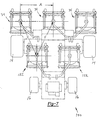
- lawn mower 150 includes common components and functions substantially similarly to lawn mower 10. Accordingly, similar components will be identified with like reference numerals. Lawn mower 150 preferably includes three side-by-side front cutting deck assemblies 34 in front of the wheels 14 and two rear cutting deck assemblies 152 positioned between the front wheels 14 and in front of the rear wheels 16. Each of the rear cutting deck assemblies 152 is positioned within the gap between two adjacent front deck assemblies 34. Rear deck assemblies 152 are substantially similar to cutting deck assemblies 34. However, cutting deck assemblies 152 are positioned adjacent one another between the front wheels. The placement of rear cutting deck assemblies 152 closer to front deck assemblies 34 allows for a reduction in lawn mower wheel base and overall length.
- lawn mower weight may be decreased while maneuverability is increased.
- the turning radius of the lawn mower may be decreased without introducing strips of uncut grass.
- the distance between any two adjacent cutting deck centers, X and Y varies between 1 and 2.5 units of cutting deck diameter, D.
- the ratio of distance X to distance A (X/A) and distance Y to distance A (Y/A) varies between 1 and 1.6.
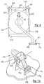
- FIG. 8 depicts another lawn mower embodiment 154 having three forward cutting deck assemblies 156 and two rear cutting assemblies 158.
- Forward cutting assemblies 156 are aligned side-by-side spaced apart from one another forward of front wheels 14.
- Rear cutting deck assemblies 158 are also aligned side-by-side and spaced apart from one another.
- Rear cutting deck assemblies 158 are positioned between front wheels 14 in similar fashion to lawn mower 150 previously described.
- each of the cutting deck assemblies 156 and 158 includes a single spindle mulching deck 160 defining a downwardly opening space.
- Deck 160 is supported by a pair of laterally spaced, generally vertically extending side plates 162 and 164.
- Two caster wheels 166 are pivotally coupled to a cross-arm 168 extending between side plates 162 and 164, such that each caster wheel 166 supports one of the side plates 162 and 164 and the deck 160 for movement over the ground.
- Each of the caster wheels 166 is coupled to cross-arm 168 via a caster shaft 170. Accordingly, each of caster wheels 166 may rotate about an axle shaft 172 and also pivot about caster shaft 170 when the vehicle is turning.
- a continuous, unitary roller 174 extends between side plates 162 and 164 and also supports side plates 162 and 164 and deck 160 for movement over the ground. In this embodiment, roller 174 is positioned behind deck 160 and extends substantially across the entire width of deck 160.
- Each of the deck assemblies includes a lifting arm 176 to pivotally interconnect each of the deck assemblies with frame 12.
- Each lifting arm 176 includes a first end 178 pivotally coupled to deck 160 and a second end 180 pivotally coupled to frame 12.
- first end 178 cooperates with a pin 182 to define an axis of rotation 184 extending laterally across deck 160 perpendicular to the forward-rearward direction of travel.
- Pin 182 rotatably couples second end 180 to a bracket 186.
- Bracket 186 is in turn pivotally coupled to a pair of stantions 188 extending from deck 160.
- a second pin 190 rotatably interconnects bracket 186 and stantions 188 for rotation about an axis 192 longitudinally extending in the forward-rearward direction of the mower 154.
- Second end 180 of lifting arm 176 includes a third pin 194 pivotally interconnecting lifting arm 176 with frame 12.
- Pin 194 defines an axis 196 laterally extending across mower 154.
- a hydraulic assembly 148 connected between lifting arm 176 and frame 12 pivots the arm about axis 196 for lifting and lowering deck 160.
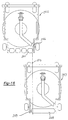
- a segmented first roller 200 is positioned behind a deck 201 laterally extending a distance less than the width of deck 201.
- Segmented roller 200 includes a plurality of roller segments 200A, 200B, 200C and 200D. It should be appreciated that segmented first roller 200 may include any number of roller segments without departing from the scope of the present invention.
- a second roller 202 is positioned forward of first roller 200. Second roller 202 is coupled to a side plate 203 and generally aligned with an outside edge of deck 201.
- a third roller 204 is aligned laterally with second roller 202 and positioned forward of first roller 200.
- Third roller 204 is coupled to a side plate 205 and generally aligned with an outside edge of deck 201.
- First roller 200, second roller 202 and third roller 204 are positioned to define a substantially uninterrupted rolling path 206 to provide an aesthetically pleasing striping of the grass.
- Second roller 202 and third roller 204 may be sized such that a portion of each of these rollers overlaps first roller 200.
- an inner edge 208 of second roller 202 may be aligned with an outer edge 210 of first roller 200 to provide the substantially uninterrupted roller path.
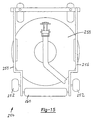
- a three-wheeled mower 212 includes two forward wheels 214 and one rear wheel 216.
- Two forward cutting deck assemblies 218 are aligned with each of the wheels 214 in the longitudinal (forward-rearward) direction of travel and laterally aligned with each other.
- Each of cutting deck assemblies 218 includes a pair of segmented rollers 220 aligned along an axis of rotation 222 and laterally spaced apart from one another a predetermined distance 224.
- Each of the forward wheels 214 is aligned with the space between rollers 220 such that the combination of rollers 220 and wheel 214 form a rolling path 226 to provide the striping effect.
- a rear cutting deck assembly 228 is positioned within the gap between forward cutting assemblies 218.
- Rear cutting deck assembly 228 is preferably laterally centered between forward cutting deck assemblies 218 to assure that all of the grass across the width of mower 212 is cut.
- forward cutting deck assemblies 218 are spread apart a distance less than the cutting width of rear cutting deck assembly 228 to further assure a complete width of cut when mower 212 is turning.
- Rear cutting deck assembly 228 is aligned with rear wheel 216 such that a first roller 230 and a second roller 232 cooperate with rear wheel 216 to stripe the grass.
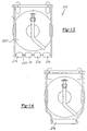
- Cutting deck assembly 234 includes a plurality of separate rollers 236 aligned and rotatably mounted to axle 238.
- Axle 238 is coupled to a first side plate 242 and a second side plate 244. Accordingly, rollers 236 support the side plates and a deck 245 for movement over the ground.
- Rollers 236 are preferably axially spaced apart a predetermined distance along axle 238 to provide an alternate striping effect. It should be appreciated that rollers 236 are positioned such that they do not extend substantially across the entire width of a mower deck 245.
- a single one-piece unitary roller 246 may be incorporated to support the side plates and deck. Roller 246 does not extend the entire width of the mower deck.
- another embodiment 250 of a cutting deck assembly includes a pair of rear wheels 252 coupled to a pair of side plates 254 and 256, respectively.
- Rear wheels 252 function to support side plates 254 and 256 along with a mower deck 258 for movement over the ground.
- cutter deck assembly 250 includes a unitary, one-piece roller 260 extending between side plates 254 and 256 a distance less than the entire width of deck 258.
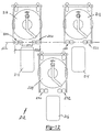
- each of the forward and rear cutting deck assemblies may be positioned relative to another in a number of ways.
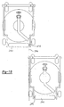
- a forward cutting deck assembly 262 includes a roller 264 having an inboard edge 266 which may be positioned in an overlapping relationship with a rear cutting deck assembly 267 having a roller 268 with an outboard edge 269.
- phantom line 270 represents, inboard edge 266 of forward cutting deck assembly 262 overlaps outboard edge 269 of rear cutting deck assembly 267 to create the appearance of one continuous roller stripe.
- an inboard edge 271 of a roller 272 may be longitudinally aligned with an outboard edge 274 of a roller 276. Accordingly, the cutting deck positions depicted in the Figure provide a substantially continuous roller stripe. As shown in Fig. 18, an inboard edge 278 of a roller 280 may be offset from an outboard edge 282 of a roller 284 as depicted by phantom line 286. In this manner, an interrupted stripe is formed in the grass as the rollers pass over.
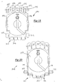
- Cutting deck assembly 290 includes a plurality of front caster wheels 292 pivotally coupled to a arcuate cross member 294 interconnecting a first side plate 296 and a second side plate 298. Each of front caster wheels 292 is pivotally coupled to cross member 294 via a caster pin 300. The plurality of caster wheels 292 provide an improved anti-scalp feature such that if any one of the caster wheels were to encounter a raised portion of turf, deck assembly 290 would be lifted to prevent the cutting blade from removing too much grass and scalping the turf.
- Cutting deck 290 also includes a pair of rear wheels 302 and a rear segmented roller assembly 304. Rear wheels 302 are pivotally coupled to each of the side plates 296 and 298. Each of the segments of segmented rear roller assembly 304 are rotatably coupled and aligned along an axle 306.
- Figure 20 depicts yet another cutting deck assembly 308 having a stepped and segmented rear roller assembly 310.
- Rear roller assembly 310 includes a pair of outboard rollers 312 coupled to side plates 314 and 316.
- Rear roller assembly 310 also includes an inboard set of rollers 318 positioned between side plates 314 and 316 and rotatably mounted on a stepped axle shaft 320.
- Rear roller assembly 310 provides a striped pattern having a width greater than the width of a deck 322.
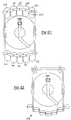
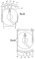
- Figures 21-24 depict additional cutting deck embodiments including various combinations of components previously introduced.
- Figures 21 and 23 include a plurality of front caster wheels 324 pivotally mounted to a cross-member 325.
- the embodiment depicted in Figure 21 includes a rearwardly mounted plurality of caster wheels 326 in lieu of a rear roller.
- Figure 22 includes a "V" shaped offset, segmented roller assembly 328 similar to the assembly shown in Figure 20 and depicted at reference numeral 310.
- Figure 24 includes a rear plurality of caster wheels 328 similar to those shown in Figure 21 at numeral 326.
- any of the aforementioned lawn mowers may have two or more decks in the front row, and one or more cutting decks in the rear row. Also, other arrangements may be used to mount the decks to frame 12.
Landscapes
- Life Sciences & Earth Sciences (AREA)
- Environmental Sciences (AREA)
- Harvester Elements (AREA)
- Peptides Or Proteins (AREA)
- Enzymes And Modification Thereof (AREA)
- Measuring Or Testing Involving Enzymes Or Micro-Organisms (AREA)
Abstract
Description
Claims (27)
- A gang-type rotary lawn mower comprising:a frame supported by front wheels and at least one rear wheel for movement over the ground;a power source which is mounted on said frame and which drives at least two of said wheels;an operator's seat mounted on said frame;a steering system enabling the operator to steer said lawn mower;at least two side-by-side front rotary cutting deck assemblies mounted on said frame in front of said front wheels, said front deck assemblies defining a gap between adjacent front deck assemblies; andat least one rear rotary cutting deck assembly mounted on said frame behind said front deck assemblies and between said front wheels, each rear deck assembly being aligned with a respective gap between adjacent front deck assemblies;each of said front and rear deck assemblies including a deck defining a downwardly opening space, at least one cutting blade mounted on a spindle for rotation therewith and a first roller supporting said deck for movement over the ground, said first roller extending only partially across the width of said deck.
- The lawn mower of Claim 1 wherein each of said front and rear deck assemblies further includes a second roller positioned in offset relation to said first roller.
- The lawn mower of Claim 2 wherein each of said front and rear deck assemblies further includes a third roller having an axis of rotation aligned with an axis of rotation of said second roller.
- The lawn mower of Claim 3 wherein each of said first, second and third rollers define a rolling path substantially uninterrupted across the width of the deck.
- The lawn mower of Claim 4 wherein said rolling path includes a portion traveled by both of said first and second rollers.
- The lawn mower of Claim 1 wherein each of said front and rear deck assemblies includes a second roller aligned with said first roller and spaced apart therefrom, said first and second rollers positioned on opposite sides of a respective wheel such that a rolling path is defined by said first roller, said second roller and said respective wheel.
- The lawn mower of Claim 6 wherein said rolling path extends substantially across the deck width.
- The lawn mower of Claim 1 wherein said first roller of said at least one front deck assembly defines a rolling path and said first roller of said corresponding at least one rear deck assembly defines a rolling path.
- The lawn mower of Claim 8 wherein said rolling path defined by said front deck assembly roller overlaps said rolling path defined by said rear deck assembly roller.
- The lawn mower of Claim 8 wherein said rolling path defined by said front deck assembly roller includes an inboard edge aligned with an outboard edge of said rolling path defined by said rear deck assembly roller.
- The lawn mower of Claim 8 wherein said rolling path defined by said front deck assembly roller is spaced apart from said rolling path defined by said rear deck assembly roller.
- The lawn mower of Claim 1 wherein each of said front and rear deck assemblies further includes a pair of rotatable wheels pivotally mounted to said frame.
- The lawn mower of Claim 12 wherein said rotatable wheels are mounted on a caster shaft.
- The lawn mower of Claim 1 further including a lifting arm pivotally interconnecting each of said front deck assemblies to said frame, said lifting arm pivoting about an axis laterally extending across said deck assembly substantially parallel to the ground and perpendicular to the direction of travel.
- The lawn mower of Claim 1 wherein said first roller is a unitary, one-piece roller.
- The lawn mower of Claim 1 wherein said first roller is a segmented roller having a plurality of roller segments.
- The lawn mower of Claim 16 wherein said roller segments are aligned along an axis of rotation.
- The lawn mower of Claim 16 wherein each of said roller segments is positioned in an offset manner from an adjacent one of said roller segments.
- A cutting deck assembly for a gang-type rotary lawn mower having a frame, the cutting deck assembly comprising:a deck defining a downwardly opening space;at least one cutting blade mounted on a spindle for rotation therewith;a pair of laterally-spaced, generally vertically extending side plates having forward ends;a first front wheel supporting one of said side plates for movement over the ground;a second front wheel supporting the other of said side plates for movement over the ground;a roller extending between said side plates supporting said side plates for movement over the ground, wherein said deck is coupled to said side plates and located in front of said roller such that the height of said deck relative to the ground is adjustable by changing the position of said deck relative to said side plates; anda lifting arm adapted to pivotally interconnect said cutting deck assembly and the frame.
- The lawn mower of Claim 19 wherein said roller is a unitary, one-piece roller.
- The lawn mower of Claim 19 wherein said roller is a segmented roller having a plurality of roller segments.
- The lawn mower of Claim 21 wherein said roller segments are aligned along an axis of rotation.
- The lawn mower of Claim 21 wherein each of said roller segments is positioned in an offset manner from an adjacent one of said roller segments.
- A gang-type rotary lawn mower comprising:a frame supported by front wheels and at least one rear wheel for movement over the ground;a power source which is mounted on said frame and which drives at least two of said wheels;an operator's seat mounted on said frame;a steering system enabling the operator to steer said lawn mower;at least two side-by-side front rotary cutting deck assemblies mounted on said frame in front of said front wheels, said front deck assemblies defining a gap between adjacent front deck assemblies; andat least one rear rotary cutting deck assembly mounted on said frame behind said front deck assemblies, each rear deck assembly being aligned with a respective gap between adjacent front deck assemblies;each of said front and rear deck assemblies including a deck defining a downwardly opening space, at least one cutting blade mounted on a spindle for rotation therewith and a first, second and third roller supporting said deck for movement over the ground, said first roller extending only partially across the width of said deck.
- The lawn mower of Claim 24 wherein said first roller and said second roller are positioned in along different axes of rotation.
- The lawn mower of Claim 25 wherein said third roller and said second roller rotate about the same axis of rotation.
- The lawn mower of Claim 26 wherein said second and third rollers are positioned forward of said first roller.
Applications Claiming Priority (2)
| Application Number | Priority Date | Filing Date | Title |
|---|---|---|---|
| US643697 | 2000-08-22 | ||
| US09/643,697 US6336312B1 (en) | 1997-02-03 | 2000-08-22 | Gang-Type rotary lawn mower with multiple rear rollers |
Publications (3)
| Publication Number | Publication Date |
|---|---|
| EP1181860A2 true EP1181860A2 (en) | 2002-02-27 |
| EP1181860A3 EP1181860A3 (en) | 2002-07-17 |
| EP1181860B1 EP1181860B1 (en) | 2009-02-18 |
Family
ID=24581907
Family Applications (1)
| Application Number | Title | Priority Date | Filing Date |
|---|---|---|---|
| EP01120134A Expired - Lifetime EP1181860B1 (en) | 2000-08-22 | 2001-08-22 | Gang type rotary lawn mower |
Country Status (6)
| Country | Link |
|---|---|
| US (1) | US6336312B1 (en) |
| EP (1) | EP1181860B1 (en) |
| JP (1) | JP5226919B2 (en) |
| AT (1) | ATE422814T1 (en) |
| AU (1) | AU779078B2 (en) |
| DE (1) | DE60137670D1 (en) |
Cited By (1)
| Publication number | Priority date | Publication date | Assignee | Title |
|---|---|---|---|---|
| ITFI20090078A1 (en) * | 2009-04-16 | 2010-10-17 | Fabrizio Bernini | LAWN MOWERS |
Families Citing this family (33)
| Publication number | Priority date | Publication date | Assignee | Title |
|---|---|---|---|---|
| US6593192B2 (en) * | 2001-04-27 | 2003-07-15 | Micron Technology, Inc. | Method of forming a dual-gated semiconductor-on-insulator device |
| FR2837347B1 (en) * | 2002-03-21 | 2004-07-30 | Kuhn Sa | AGRICULTURAL MOWER COMPRISING A CARRIER VEHICLE AND SEVERAL WORKING UNITS |
| US8166735B1 (en) | 2002-11-13 | 2012-05-01 | Wing Product Development Corp. | Pull type gang mower |
| US7793487B1 (en) | 2002-11-13 | 2010-09-14 | Wings Product Development Corporation | Pull type gang mower |
| US20040148917A1 (en) * | 2003-01-13 | 2004-08-05 | Nicholson Hirzel | Variable contour mowing machine |
| US20050034438A1 (en) * | 2003-02-12 | 2005-02-17 | Burke Steven A. | Towable rotary mowing apparatus |
| US20050198933A1 (en) * | 2004-03-15 | 2005-09-15 | Klein John A. | Deck for mowers |
| US7237374B2 (en) | 2003-09-26 | 2007-07-03 | Scag Power Equipment, Inc. | Roller assembly for striping a lawn |
| US6928798B2 (en) * | 2004-01-02 | 2005-08-16 | Textron Inc. | Swing out arm for rear rotary deck |
| US7287363B2 (en) * | 2004-04-20 | 2007-10-30 | Deere & Company | Riding mower having multiple cutting units |
| US20060079419A1 (en) * | 2004-10-08 | 2006-04-13 | Julie Ann Wagner | Depositable solids |
| JP4874737B2 (en) * | 2006-08-09 | 2012-02-15 | 株式会社共栄社 | Connecting link device for mower units in multiple rotary mowers |
| US7690178B2 (en) * | 2006-10-02 | 2010-04-06 | Kubota Tractor Corporation | Lawn mower with grass striping mechanism |
| US7475530B2 (en) * | 2007-03-02 | 2009-01-13 | Textron Inc. | Articulating swing-out arm |
| US7637090B2 (en) * | 2007-10-17 | 2009-12-29 | Deere & Company | Roller configuration having reduced overlap for a grass mowing machine |
| US7716907B2 (en) | 2008-08-15 | 2010-05-18 | Deere & Company | Height of cut adjustment mechanism for rotary cutting deck |
| US20100300055A1 (en) * | 2009-05-28 | 2010-12-02 | Dan Dvorak | Wide-span mowing device |
| US8104253B2 (en) * | 2010-03-31 | 2012-01-31 | The Toro Company | Gang reel mower with differing front and rear reel cutting unit setup for improving aftercut appearance |
| US9027318B2 (en) * | 2012-02-07 | 2015-05-12 | IHI Shibaura Machinery Corporation | Reel lawn mower with main body, reel cutting unit, and connection structure for connecting reel cutting unit to main body such that reel cutting unit is rollable |
| US9616721B2 (en) * | 2015-08-19 | 2017-04-11 | William Perez | Universal offset lawn mower towing device |
| GB201616659D0 (en) * | 2016-09-30 | 2016-11-16 | Meyer Robin S | Mower apparatus |
| US10136579B2 (en) | 2017-01-20 | 2018-11-27 | David D. Button | Mower for attachment to an agricultural vehicle |
| US10939615B2 (en) * | 2017-10-26 | 2021-03-09 | Firefly Automatix, Inc. | Adjustable mower deck |
| US11160207B2 (en) * | 2017-10-26 | 2021-11-02 | Firefly Automatix, Inc. | Height adjustable mower deck |
| US20200253113A1 (en) | 2019-02-07 | 2020-08-13 | Textron Inc. | Gang-type lawn mower |
| DE102019103335A1 (en) * | 2019-02-11 | 2020-08-13 | Brüggli | Device, preferably autonomous robotic device, for mowing grass |
| US11206762B2 (en) | 2019-07-26 | 2021-12-28 | David D. Button | Crop row mower |
| US12290023B2 (en) | 2021-01-20 | 2025-05-06 | Venture Products, Inc. | Method and apparatus for mounting a flail mower |
| US12178154B2 (en) | 2021-01-20 | 2024-12-31 | Venture Products, Inc. | Method and apparatus for mounting a flail mower |
| US12250901B2 (en) * | 2021-01-20 | 2025-03-18 | Venture Products, Inc. | Method and apparatus for mounting a flail mower |
| US12256667B2 (en) * | 2021-01-20 | 2025-03-25 | Venture Products, Inc. | Method and apparatus for mounting a flail mower |
| US12114600B2 (en) * | 2021-03-02 | 2024-10-15 | Deere & Company | Composite mower deck |
| KR102722509B1 (en) | 2022-06-21 | 2024-10-29 | 유한회사 웅진기계 | Weed removal apparatus for weed removal robot |
Citations (1)
| Publication number | Priority date | Publication date | Assignee | Title |
|---|---|---|---|---|
| US5915496A (en) | 1996-08-26 | 1999-06-29 | Ransomes America Corporation | Parallel-series four-wheel-drive hydraulic circuit for a riding lawn mower |
Family Cites Families (33)
| Publication number | Priority date | Publication date | Assignee | Title |
|---|---|---|---|---|
| US3118266A (en) | 1964-01-21 | Riding type power mower with floating blades | ||
| GB163300A (en) * | 1920-05-13 | 1922-07-27 | Charles Campbell Worthington | Improvements in and relating to lawn mowers |
| US1831681A (en) * | 1928-10-19 | 1931-11-10 | Miller Josephus | Edge trimming and mowing machine |
| US1961710A (en) | 1932-03-02 | 1934-06-05 | Pol John Baptiste | Gang lawn mower |
| US2168706A (en) * | 1938-06-13 | 1939-08-08 | Moto Mower Company | Lawn mower |
| US2504259A (en) | 1947-07-15 | 1950-04-18 | Foster M Ford | Mower |
| GB755800A (en) * | 1954-09-03 | 1956-08-29 | Alexander Shanks & Son Ltd | Improvements in or relating to mowing machines |
| US2936561A (en) | 1958-09-09 | 1960-05-17 | Toro Mfg Corp | Gang mower assembly for utility tractors |
| US3070938A (en) | 1960-06-20 | 1963-01-01 | Shunk Mfg Company | Grass mowers |
| US3135079A (en) | 1962-08-24 | 1964-06-02 | Thomas J Dunn | Mowing apparatus |
| US3410063A (en) * | 1964-08-19 | 1968-11-12 | Toro Mfg Corp | Mowing apparatus |
| NL7804519A (en) | 1978-04-27 | 1978-08-31 | Texas Industries Inc | Tractor pulling three part mowing unit in combination - in which mowers are connected to tractor by three point hydraulic lifting device |
| US4308713A (en) | 1980-04-28 | 1982-01-05 | Terrain King Corporation | Hydraulically driven mower |
| US4478026A (en) * | 1983-06-03 | 1984-10-23 | Ekoeg Industries, Inc. | Gang reel mower |
| US4769976A (en) | 1987-02-11 | 1988-09-13 | The Toro Company | Method and apparatus for supporting a reel unit |
| US4926621A (en) | 1988-05-20 | 1990-05-22 | Torras Robert M | Mowing tractor with towed mower |
| US4901507A (en) | 1988-12-05 | 1990-02-20 | Cracraft Larry D | Pivoted deck lawnmower |
| US5137100A (en) | 1990-10-22 | 1992-08-11 | Ultra Hydraulics Limited | Hydrostatic transmissions |
| GB9103860D0 (en) * | 1991-02-25 | 1991-04-10 | Electrolux Northern | Grass cutting machines |
| US5280695A (en) | 1992-02-07 | 1994-01-25 | Nunes Manufacturing, Inc. | Wide area lawnmower |
| US5297378A (en) | 1992-05-13 | 1994-03-29 | Deere & Company | Suspension mechanism for reel mowers |
| US5343680A (en) | 1992-09-03 | 1994-09-06 | Deere & Company | Suspension mechanism for reel mowers |
| US5293729A (en) | 1992-10-07 | 1994-03-15 | Deere & Company | Pivot mechanism for reel mower cutting units |
| US5355665A (en) | 1993-04-13 | 1994-10-18 | Mtd Products Inc. | Full flotation mower deck |
| ATE166793T1 (en) * | 1993-07-28 | 1998-06-15 | Athar Int Serv Sa | METHOD AND DEVICES FOR MARKING LAWN |
| US5481857A (en) | 1993-09-03 | 1996-01-09 | Kubota Corporation | Mower blade mounting structure |
| US5497604A (en) | 1994-02-03 | 1996-03-12 | The Toro Company | Supervisor switch for turf mower |
| US5423565A (en) | 1994-06-08 | 1995-06-13 | Smith; Frederick; M. | Mower hitch for lawn tractor |
| US5412932A (en) | 1994-08-10 | 1995-05-09 | Textron Inc. | Motor-powered lawn mower |
| US5533326A (en) * | 1995-02-24 | 1996-07-09 | The Toro Company | Reel mower |
| US6047530A (en) * | 1997-02-03 | 2000-04-11 | Textron, Inc. | Gang-type rotary lawn mower |
| JP2935983B2 (en) * | 1997-04-08 | 1999-08-16 | 株式会社アサヒ | Self-propelled green compaction vehicle |
| US6101794A (en) * | 1998-06-03 | 2000-08-15 | Terracare Products Company, Inc. | Mower |
-
2000
- 2000-08-22 US US09/643,697 patent/US6336312B1/en not_active Expired - Lifetime
-
2001
- 2001-08-22 DE DE60137670T patent/DE60137670D1/en not_active Expired - Lifetime
- 2001-08-22 AT AT01120134T patent/ATE422814T1/en not_active IP Right Cessation
- 2001-08-22 EP EP01120134A patent/EP1181860B1/en not_active Expired - Lifetime
- 2001-08-22 JP JP2001252105A patent/JP5226919B2/en not_active Expired - Fee Related
- 2001-08-22 AU AU63592/01A patent/AU779078B2/en not_active Ceased
Patent Citations (1)
| Publication number | Priority date | Publication date | Assignee | Title |
|---|---|---|---|---|
| US5915496A (en) | 1996-08-26 | 1999-06-29 | Ransomes America Corporation | Parallel-series four-wheel-drive hydraulic circuit for a riding lawn mower |
Cited By (2)
| Publication number | Priority date | Publication date | Assignee | Title |
|---|---|---|---|---|
| ITFI20090078A1 (en) * | 2009-04-16 | 2010-10-17 | Fabrizio Bernini | LAWN MOWERS |
| EP2241172A1 (en) | 2009-04-16 | 2010-10-20 | Fabrizio Bernini | Lawn-mower |
Also Published As
| Publication number | Publication date |
|---|---|
| JP2002176821A (en) | 2002-06-25 |
| AU779078B2 (en) | 2005-01-06 |
| AU6359201A (en) | 2002-02-28 |
| US6336312B1 (en) | 2002-01-08 |
| DE60137670D1 (en) | 2009-04-02 |
| JP5226919B2 (en) | 2013-07-03 |
| EP1181860B1 (en) | 2009-02-18 |
| EP1181860A3 (en) | 2002-07-17 |
| ATE422814T1 (en) | 2009-03-15 |
Similar Documents
| Publication | Publication Date | Title |
|---|---|---|
| EP1181860B1 (en) | Gang type rotary lawn mower | |
| US6047530A (en) | Gang-type rotary lawn mower | |
| US6484481B1 (en) | Rotary cutting unit with ovate rollers and front corner cut-outs | |
| US6351929B1 (en) | Triplex trim mower with laterally adjustable cutting units | |
| EP0342700B1 (en) | Mowing tractor with towed mower | |
| US12543645B2 (en) | Two-stage mowing apparatus and method | |
| US5533326A (en) | Reel mower | |
| US11382263B2 (en) | Articulating cutting deck | |
| AU783807B2 (en) | Mower cutting chamber | |
| US20030140610A1 (en) | Variable offset rotary mower apparatus | |
| CA2232127C (en) | Counterrotation mulching mower and blade assembly | |
| US20080072556A1 (en) | Rotary zero-turn steer-by-wire mower | |
| AU1365388A (en) | Method and apparatus for supporting a reel unit | |
| US7337600B2 (en) | Grass striping apparatus for use with lawn vehicle | |
| US4351143A (en) | Ground support system for a grass cutting machine | |
| US20210076567A1 (en) | Cutting deck assembly and vehicle including same | |
| EP3874933B1 (en) | Height of cut and rake adjustment system | |
| DE602005000790T2 (en) | Riding Mowers | |
| EP1900274B1 (en) | Mechanism for offsetting cutting units for a grass mowing machine and grass mowing machine | |
| US20050268588A1 (en) | Mower cutting deck having blow-out baffle, and method of using same | |
| GB2603832A (en) | Ground working vehicle with rear drive roller | |
| JPS6331Y2 (en) | ||
| US20220304225A1 (en) | Height of cut adjustment system | |
| GB2170983A (en) | Air-supported rotary gang mower | |
| JPH05184216A (en) | Lawn mower |
Legal Events
| Date | Code | Title | Description |
|---|---|---|---|
| PUAI | Public reference made under article 153(3) epc to a published international application that has entered the european phase |
Free format text: ORIGINAL CODE: 0009012 |
|
| AK | Designated contracting states |
Kind code of ref document: A2 Designated state(s): AT BE CH CY DE DK ES FI FR GB GR IE IT LI LU MC NL PT SE TR |
|
| AX | Request for extension of the european patent |
Free format text: AL;LT;LV;MK;RO;SI |
|
| PUAL | Search report despatched |
Free format text: ORIGINAL CODE: 0009013 |
|
| AK | Designated contracting states |
Kind code of ref document: A3 Designated state(s): AT BE CH CY DE DK ES FI FR GB GR IE IT LI LU MC NL PT SE TR |
|
| AX | Request for extension of the european patent |
Free format text: AL;LT;LV;MK;RO;SI |
|
| 17P | Request for examination filed |
Effective date: 20021030 |
|
| AKX | Designation fees paid |
Designated state(s): AT BE CH CY DE DK ES FI FR GB GR IE IT LI LU MC NL PT SE TR |
|
| 17Q | First examination report despatched |
Effective date: 20060302 |
|
| GRAP | Despatch of communication of intention to grant a patent |
Free format text: ORIGINAL CODE: EPIDOSNIGR1 |
|
| GRAS | Grant fee paid |
Free format text: ORIGINAL CODE: EPIDOSNIGR3 |
|
| GRAA | (expected) grant |
Free format text: ORIGINAL CODE: 0009210 |
|
| RIN1 | Information on inventor provided before grant (corrected) |
Inventor name: KNURR, RANDAL S. Inventor name: BEDNAR, RICHARD D. |
|
| AK | Designated contracting states |
Kind code of ref document: B1 Designated state(s): AT BE CH CY DE DK ES FI FR GB GR IE IT LI LU MC NL PT SE TR |
|
| REG | Reference to a national code |
Ref country code: GB Ref legal event code: FG4D |
|
| REG | Reference to a national code |
Ref country code: CH Ref legal event code: EP |
|
| REG | Reference to a national code |
Ref country code: IE Ref legal event code: FG4D |
|
| REF | Corresponds to: |
Ref document number: 60137670 Country of ref document: DE Date of ref document: 20090402 Kind code of ref document: P |
|
| PG25 | Lapsed in a contracting state [announced via postgrant information from national office to epo] |
Ref country code: FI Free format text: LAPSE BECAUSE OF FAILURE TO SUBMIT A TRANSLATION OF THE DESCRIPTION OR TO PAY THE FEE WITHIN THE PRESCRIBED TIME-LIMIT Effective date: 20090218 Ref country code: NL Free format text: LAPSE BECAUSE OF FAILURE TO SUBMIT A TRANSLATION OF THE DESCRIPTION OR TO PAY THE FEE WITHIN THE PRESCRIBED TIME-LIMIT Effective date: 20090218 Ref country code: ES Free format text: LAPSE BECAUSE OF FAILURE TO SUBMIT A TRANSLATION OF THE DESCRIPTION OR TO PAY THE FEE WITHIN THE PRESCRIBED TIME-LIMIT Effective date: 20090529 |
|
| NLV1 | Nl: lapsed or annulled due to failure to fulfill the requirements of art. 29p and 29m of the patents act | ||
| PG25 | Lapsed in a contracting state [announced via postgrant information from national office to epo] |
Ref country code: SE Free format text: LAPSE BECAUSE OF FAILURE TO SUBMIT A TRANSLATION OF THE DESCRIPTION OR TO PAY THE FEE WITHIN THE PRESCRIBED TIME-LIMIT Effective date: 20090518 Ref country code: AT Free format text: LAPSE BECAUSE OF FAILURE TO SUBMIT A TRANSLATION OF THE DESCRIPTION OR TO PAY THE FEE WITHIN THE PRESCRIBED TIME-LIMIT Effective date: 20090218 |
|
| PG25 | Lapsed in a contracting state [announced via postgrant information from national office to epo] |
Ref country code: BE Free format text: LAPSE BECAUSE OF FAILURE TO SUBMIT A TRANSLATION OF THE DESCRIPTION OR TO PAY THE FEE WITHIN THE PRESCRIBED TIME-LIMIT Effective date: 20090218 |
|
| PG25 | Lapsed in a contracting state [announced via postgrant information from national office to epo] |
Ref country code: DK Free format text: LAPSE BECAUSE OF FAILURE TO SUBMIT A TRANSLATION OF THE DESCRIPTION OR TO PAY THE FEE WITHIN THE PRESCRIBED TIME-LIMIT Effective date: 20090218 Ref country code: PT Free format text: LAPSE BECAUSE OF FAILURE TO SUBMIT A TRANSLATION OF THE DESCRIPTION OR TO PAY THE FEE WITHIN THE PRESCRIBED TIME-LIMIT Effective date: 20090727 |
|
| PLBE | No opposition filed within time limit |
Free format text: ORIGINAL CODE: 0009261 |
|
| STAA | Information on the status of an ep patent application or granted ep patent |
Free format text: STATUS: NO OPPOSITION FILED WITHIN TIME LIMIT |
|
| 26N | No opposition filed |
Effective date: 20091119 |
|
| PG25 | Lapsed in a contracting state [announced via postgrant information from national office to epo] |
Ref country code: MC Free format text: LAPSE BECAUSE OF NON-PAYMENT OF DUE FEES Effective date: 20090831 |
|
| REG | Reference to a national code |
Ref country code: CH Ref legal event code: PL |
|
| PG25 | Lapsed in a contracting state [announced via postgrant information from national office to epo] |
Ref country code: CH Free format text: LAPSE BECAUSE OF NON-PAYMENT OF DUE FEES Effective date: 20090831 Ref country code: LI Free format text: LAPSE BECAUSE OF NON-PAYMENT OF DUE FEES Effective date: 20090831 |
|
| REG | Reference to a national code |
Ref country code: IE Ref legal event code: MM4A |
|
| PG25 | Lapsed in a contracting state [announced via postgrant information from national office to epo] |
Ref country code: IE Free format text: LAPSE BECAUSE OF NON-PAYMENT OF DUE FEES Effective date: 20090822 |
|
| PG25 | Lapsed in a contracting state [announced via postgrant information from national office to epo] |
Ref country code: GR Free format text: LAPSE BECAUSE OF FAILURE TO SUBMIT A TRANSLATION OF THE DESCRIPTION OR TO PAY THE FEE WITHIN THE PRESCRIBED TIME-LIMIT Effective date: 20090519 |
|
| PG25 | Lapsed in a contracting state [announced via postgrant information from national office to epo] |
Ref country code: IT Free format text: LAPSE BECAUSE OF FAILURE TO SUBMIT A TRANSLATION OF THE DESCRIPTION OR TO PAY THE FEE WITHIN THE PRESCRIBED TIME-LIMIT Effective date: 20090218 |
|
| PG25 | Lapsed in a contracting state [announced via postgrant information from national office to epo] |
Ref country code: LU Free format text: LAPSE BECAUSE OF NON-PAYMENT OF DUE FEES Effective date: 20090822 |
|
| PG25 | Lapsed in a contracting state [announced via postgrant information from national office to epo] |
Ref country code: TR Free format text: LAPSE BECAUSE OF FAILURE TO SUBMIT A TRANSLATION OF THE DESCRIPTION OR TO PAY THE FEE WITHIN THE PRESCRIBED TIME-LIMIT Effective date: 20090218 |
|
| PG25 | Lapsed in a contracting state [announced via postgrant information from national office to epo] |
Ref country code: CY Free format text: LAPSE BECAUSE OF FAILURE TO SUBMIT A TRANSLATION OF THE DESCRIPTION OR TO PAY THE FEE WITHIN THE PRESCRIBED TIME-LIMIT Effective date: 20090218 |
|
| REG | Reference to a national code |
Ref country code: FR Ref legal event code: PLFP Year of fee payment: 15 |
|
| REG | Reference to a national code |
Ref country code: FR Ref legal event code: PLFP Year of fee payment: 16 |
|
| PGFP | Annual fee paid to national office [announced via postgrant information from national office to epo] |
Ref country code: GB Payment date: 20160830 Year of fee payment: 16 Ref country code: DE Payment date: 20160826 Year of fee payment: 16 |
|
| PGFP | Annual fee paid to national office [announced via postgrant information from national office to epo] |
Ref country code: FR Payment date: 20160825 Year of fee payment: 16 |
|
| REG | Reference to a national code |
Ref country code: DE Ref legal event code: R119 Ref document number: 60137670 Country of ref document: DE |
|
| GBPC | Gb: european patent ceased through non-payment of renewal fee |
Effective date: 20170822 |
|
| REG | Reference to a national code |
Ref country code: FR Ref legal event code: ST Effective date: 20180430 |
|
| PG25 | Lapsed in a contracting state [announced via postgrant information from national office to epo] |
Ref country code: GB Free format text: LAPSE BECAUSE OF NON-PAYMENT OF DUE FEES Effective date: 20170822 Ref country code: DE Free format text: LAPSE BECAUSE OF NON-PAYMENT OF DUE FEES Effective date: 20180301 |
|
| PG25 | Lapsed in a contracting state [announced via postgrant information from national office to epo] |
Ref country code: FR Free format text: LAPSE BECAUSE OF NON-PAYMENT OF DUE FEES Effective date: 20170831 |