EP1181605B1 - Cable termination - Google Patents
Cable termination Download PDFInfo
- Publication number
- EP1181605B1 EP1181605B1 EP00929710A EP00929710A EP1181605B1 EP 1181605 B1 EP1181605 B1 EP 1181605B1 EP 00929710 A EP00929710 A EP 00929710A EP 00929710 A EP00929710 A EP 00929710A EP 1181605 B1 EP1181605 B1 EP 1181605B1
- Authority
- EP
- European Patent Office
- Prior art keywords
- cable
- cable termination
- termination according
- base member
- engagement member
- Prior art date
- Legal status (The legal status is an assumption and is not a legal conclusion. Google has not performed a legal analysis and makes no representation as to the accuracy of the status listed.)
- Expired - Lifetime
Links
- 230000003287 optical effect Effects 0.000 claims description 11
- 239000013307 optical fiber Substances 0.000 claims description 10
- 239000000835 fiber Substances 0.000 description 2
- 238000009434 installation Methods 0.000 description 2
- 239000004593 Epoxy Substances 0.000 description 1
- 230000004308 accommodation Effects 0.000 description 1
- 238000007792 addition Methods 0.000 description 1
- 238000005452 bending Methods 0.000 description 1
- 239000011521 glass Substances 0.000 description 1
- 238000003780 insertion Methods 0.000 description 1
- 230000037431 insertion Effects 0.000 description 1
- 239000000463 material Substances 0.000 description 1
- 239000002184 metal Substances 0.000 description 1
- 238000012986 modification Methods 0.000 description 1
- 230000004048 modification Effects 0.000 description 1
Images

Classifications
-
- G—PHYSICS
- G02—OPTICS
- G02B—OPTICAL ELEMENTS, SYSTEMS OR APPARATUS
- G02B6/00—Light guides; Structural details of arrangements comprising light guides and other optical elements, e.g. couplings
- G02B6/44—Mechanical structures for providing tensile strength and external protection for fibres, e.g. optical transmission cables
-
- G—PHYSICS
- G02—OPTICS
- G02B—OPTICAL ELEMENTS, SYSTEMS OR APPARATUS
- G02B6/00—Light guides; Structural details of arrangements comprising light guides and other optical elements, e.g. couplings
- G02B6/44—Mechanical structures for providing tensile strength and external protection for fibres, e.g. optical transmission cables
- G02B6/4439—Auxiliary devices
- G02B6/4471—Terminating devices ; Cable clamps
- G02B6/44765—Terminating devices ; Cable clamps with means for strain-relieving to exterior cable layers
-
- G—PHYSICS
- G02—OPTICS
- G02B—OPTICAL ELEMENTS, SYSTEMS OR APPARATUS
- G02B6/00—Light guides; Structural details of arrangements comprising light guides and other optical elements, e.g. couplings
- G02B6/44—Mechanical structures for providing tensile strength and external protection for fibres, e.g. optical transmission cables
- G02B6/4439—Auxiliary devices
- G02B6/4471—Terminating devices ; Cable clamps
- G02B6/4477—Terminating devices ; Cable clamps with means for strain-relieving to interior strengths element
Definitions
- the present invention relates to a cable termination. More in particular, the present invention relates to a cable termination for an optical fibre cable having at least one non-coaxial strength member, the cable termination comprising a base member and an engagement member for engaging the strength member of the cable.
- a cable termination serves to mechanically stabilise the end of a cable while organising and protecting the optical fibres emerging from the cable core.
- WO 91/12548 discloses a cable termination for use with a slotted core optical fibre cables having a central strength member.
- the optical fibres are accommodated in slots or grooves in the circumference of the core, while the strength member (for example a metal wire) is coaxially arranged in the centre of the core.
- the strength member for example a metal wire
- US 4,795,230 discloses a termination for this type of cable.
- optical fibres are arranged in the centre of the core, while the one or more strength members are arranged at the outside of the core, that is, in a position which is spaced apart from the centre or, in other words, non-coaxial.
- This type of cable is often provided with two substantially diametrically opposed strength members.
- a cable termination as defined in the preamble is according to the present invention characterised in that the engagement member is rotatably mounted on the base member so as to allow rotation about the longitudinal axis of the cable.
- the rotation can be achieved by providing, for example, a single slot in the base member, the slot extending transverse to the base member's longitudinal direction (here assumed to coincide with the cable's and the termination's longitudinal direction), and the engagement member having a single protrusion accommodated in the slot.
- the base member could be provided with one or more protrusions which are accommodated in slots in the engagement member.
- the base member is provided with at least two transverse slots for accommodating protrusions extending from the engagement member.
- At least one of the protrusions is constituted by a screw allowing the limiting member to be fixed.
- This allows the engagement member to be fixed at a certain angle.
- the engagement member can thus freely rotate to achieve the necessary alignment and is subsequently fixed in the aligned position to provide mechanical stability.
- the allowed rotation is a rotation over a minimum of approximately 45° and a maximum of approximately 180°.
- the engagement member merely limits the longitudinal extension of the at least one strength member.
- the engagement member can thus be provided with "pockets" which are open at the side of the engagement member facing the cable so a strength member can be inserted, while the closed end of the pocket prevents the strength member from extending beyond the engagement member. It will be understood that in such an embodiment the strength members are only loosely “engaged”, but that in other embodiments the strength members may be securely fixed in the engagement members, for example by clamping.
- a variety of cable diameters can be accommodated in the cable termination of the present invention when the engagement member is provided with openings for accommodating strength members, the substantially longitudinal cross-sections of the openings being arranged in a substantially V-shaped configuration.
- a particular embodiment is designed such that the base member is arranged for accommodating two parallel optical fibre cables and comprises two engagement members in parallel.
- a break-out member is mounted on the base member.
- the break-out member serves to organise the optical fibres emerging from the cable core.
- a particular advantageous embodiment of a break-out member for use in a cable termination as defined above or in other types of cable terminations comprises a pair of mutually connected break-out blocks separated by a slot, each block comprising a plurality of through-holes for accommodating optical fibres.
- the break-out member comprises a pair of mutually connected break-out blocks separated by a slot, each block comprising a plurality of through-holes.
- the present invention further provides a kit-of-parts for providing a cable termination.
- the cable termination 1 shown merely by way of example in Fig. 1 comprises a base member 2, an engagement member 3, a break-out member or organiser 9, a fixation tongue 7 and a cable clamp 17.
- An optical fibre cable 20 having strength members 21, optical fibres 22 and a core 23 is accommodated in the termination 1.
- the longitudinal base member 2 has a partial circular circumference.
- the substantially tubular shape allows a partial rotation of the engagement member 3 and facilitates the accommodation of the substantially round break-out member 9.
- Two transverse slots 4 in the wall of the base member 2 each accommodate a protrusion (5 in Fig. 2) of the engagement member 3. This arrangement allows a partial rotation of the engagement member 3 relative to the basement 2 while preventing any longitudinal motion.
- the use of two pairs of slots and protrusions, spaced apart in the longitudinal direction, provides additional stability.
- the engagement member 3 is provided with two openings 6 for accommodating a strength member 21 each. These openings 6 are closed off at the other end of the engagement member 3 so as to limit the extension of the strength members 21.
- the strength members 21 are preferably not attached to the engagement members 3 so as to minimise the risk of breaking, thus allowing lateral movement of the strength members 21 due to the cross-sectional shape of the openings 6.
- a longitudinally extending fixation tongue 7 is integral with the base member 2 and is provided with a fixation opening 18 for accommodating a screw or the like.
- a connecting member 8 allows an optional strength member connector (not shown) to be mounted for fixedly attaching strength members 21 to the termination 1 if this should be required.
- the size and shape of the tongue 7 may depend on the particular application of the cable termination 1.
- a protrusion 5 here shown to be a screw, protrudes through a slot 4 (see Fig. 1) in the base member 2 and defines the range of rotation.
- the engagement member 3 is shown to have two openings 6, each having a substantially longitudinal cross-section. As further illustrated in Fig. 3, the substantially V-shaped arrangement of the openings 6 allows a wide range of cables to be accommodated.
- a cable 20 having a relatively small diameter has strength members 21 which are accommodated in the openings 6, while a cable 20 having a relatively large diameter has strength members 21' which are accommodated in the far corners of the same openings 6.
- the arrangement of Fig. 3 has the advantage of increased flexibility. Therefore only one opening 6 is provided for each strength member, the size and shape of the opening being chosen so as to be able to accommodate the strength member independent from the cable diameter.
- the engagement member 3 shown has a generally U-shaped cross-section which leaves the centre part of the termination free for the passage of optical fibres.
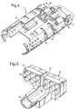
- the embodiment of Fig. 4 is designed for accommodating parallel cables, in particular cable loops.
- the cable termination 1 has a base member 2 which accommodates two engagement members 3, each being rotatable about their respective longitudinal axes. Two sets of slots 4 define the allowed rotation in conjunction with protrusions 5.
- each engagement member is provided with one integral protrusion 5 and one screw hole 19 for accommodating a fixing screw which serves as a second protrusion.
- An elongated or substantially oval break-out member 9 is accommodated in the base member 2 and may be fastened by means of screws (not shown).
- the break-out member 9 of Fig. 4 has through-holes 10 which are open towards the perimeter of the member 9. This allows a "wrap-around" insertion of optical fibre into the holes 10 and thereby permits uncut fibres to be accommodated.
- An enlarged central through-hole 13 may be used for organising cut fibres.
- the break-out member 9 shown in Fig. 5 may be substituted for the one shown in Fig. 4 when a higher degree of organisation is required.
- This break-out member 9 has two parts or blocks 11 which are mutually connected at the bottom end of the member 9 but are separated at the top end by a slot 12.
- Each block 11 has, in the embodiment shown, six through-holes 10 for accommodating (cut) optical fibres.
- the break-out member 9 of Fig. 5 therefore allows a high degree of organisation by being able to accommodate both cut and uncut fibres and by being able to separate the cut fibres into two distinct groups.
- the member is particularly suitable for loop terminations where part of the fibres is looped back and part is spliced to further fibres.
- This break-out member 9 may be mounted on the tongue 7 by means of screws (not shown) which are received in screw-threaded connecting members 8.
- the member is suitably mounted with the main part of the fibre guide 14 pointing away from the engagement member 3.
- Holding tubes (not shown) for holding optical fibres may be inserted in the through-holes 10.
- break-out 9 shown in Figs. 4 and 5 can also be used in cable terminations not having rotatable (or generally movable) engagement members.
Landscapes
- Physics & Mathematics (AREA)
- General Physics & Mathematics (AREA)
- Optics & Photonics (AREA)
- Light Guides In General And Applications Therefor (AREA)
- Optical Couplings Of Light Guides (AREA)
Description
Claims (17)
- Cable termination (1) for an optical fibre cable (20) having at least one non-coaxial strength member (21), the cable termination (1) comprising a base member (2) and an engagement member (3) for engaging the strength member (21) of the cable (20),
characterised in that
the engagement member (3) is rotatably mounted on the base member (2) so as to allow rotation about the longitudinal axis of the cable (20). - Cable termination according to claim 1, wherein the base member (2) is provided with at least two transverse slots (4) for accommodating protrusions (5) extending from the engagement member (3).
- Cable termination according to claim 2, wherein at least one of the protrusions (5) is constituted by a screw allowing the engagement member (3) to be fixed.
- Cable termination according to any of the preceding claims, wherein the allowed rotation is a rotation over a minimum of approximately 45° and a maximum of approximately 180°.
- Cable termination according to any of the preceding claims, wherein the engagement member (3) is arranged for engaging two strength members (21).
- Cable termination according to any of the preceding claims, wherein the engagement member (3) merely limits the longitudinal extension of the at least one strength member (21).
- Cable termination according to any of the preceding claims, wherein the engagement member (3) is provided with openings (6) for accommodating strength members (21), the substantially longitudinal cross-sections of the openings (6) being arranged in a substantially V-shaped configuration.
- Cable termination according to any of the preceding claims, wherein the base member (2) is provided with a fixation tongue (7) extending in the longitudinal direction.
- Cable termination according to any of the preceding claims, wherein the base member (2) is provided with a cable jacket clamp (17).
- Cable termination according to any of the preceding claims, wherein the base member (2) is arranged for accommodating two parallel optical fibre cables (20) and comprises two engagement members (3) in parallel.
- Cable termination according to any of the preceding claims, wherein a break-out member (9) is mounted on the base member (2), the break-out member (9) comprising a plurality of through-holes (10) for accommodating optical fibres (22).
- Cable termination according to claim 11, wherein the through-holes (10) are concentrically arranged.
- Cable termination according to claim 11 or 12, wherein the break-out member (9) comprises a pair of mutually connected break-out blocks (11) separated by a slot (12), each block (11) comprising a plurality of through-holes (10).
- Cable termination according to claim 11, wherein each block (11) comprises six through-holes (10).
- Cable termination according to claims 13 or 14, wherein the slot (12) is provided with a substantially tubular widened end (13) for accommodating optical fibres.
- Cable termination according to any one of the preceding claims, further provided with a housing.
- Kit-of-parts for forming a cable termination (1) for an optical fibre cable (20) having at least one non-coaxial strength member (21), the kit-of-parts comprising a base member (2) and an engagement member (3) for engaging the strength member (21) of the cable (20),
characterised in that the engagement member (3) is rotatably mountable on the base member (2) so as to allow rotation about the longitudinal axis of the cable (20).
Applications Claiming Priority (5)
| Application Number | Priority Date | Filing Date | Title |
|---|---|---|---|
| GB9911612 | 1999-05-19 | ||
| GBGB9911612.1A GB9911612D0 (en) | 1999-05-19 | 1999-05-19 | Optical fibre organiser |
| GB0010283A GB0010283D0 (en) | 2000-04-28 | 2000-04-28 | Cable termination |
| GB0010283 | 2000-04-28 | ||
| PCT/GB2000/001863 WO2000072072A1 (en) | 1999-05-19 | 2000-05-15 | Cable termination |
Publications (2)
| Publication Number | Publication Date |
|---|---|
| EP1181605A1 EP1181605A1 (en) | 2002-02-27 |
| EP1181605B1 true EP1181605B1 (en) | 2003-04-16 |
Family
ID=26244182
Family Applications (1)
| Application Number | Title | Priority Date | Filing Date |
|---|---|---|---|
| EP00929710A Expired - Lifetime EP1181605B1 (en) | 1999-05-19 | 2000-05-15 | Cable termination |
Country Status (14)
| Country | Link |
|---|---|
| EP (1) | EP1181605B1 (en) |
| KR (1) | KR20010113959A (en) |
| CN (1) | CN1361878A (en) |
| AR (1) | AR026858A1 (en) |
| AT (1) | ATE237822T1 (en) |
| AU (1) | AU769238B2 (en) |
| BR (1) | BR0010629A (en) |
| CZ (1) | CZ20014136A3 (en) |
| DE (1) | DE60002195T2 (en) |
| HU (1) | HU222921B1 (en) |
| PE (1) | PE20010311A1 (en) |
| PL (1) | PL351745A1 (en) |
| TR (1) | TR200103295T2 (en) |
| WO (1) | WO2000072072A1 (en) |
Families Citing this family (17)
| Publication number | Priority date | Publication date | Assignee | Title |
|---|---|---|---|---|
| DE10338848A1 (en) * | 2003-08-20 | 2005-03-17 | CCS Technology, Inc., Wilmington | Optical cable interceptor, cable sleeve with such interceptor, and method of providing optical cable interceptor using such interceptor |
| EP1744191B1 (en) * | 2005-06-22 | 2010-07-07 | CCS Technology, Inc. | Device for supporting cables |
| DE202005009932U1 (en) * | 2005-06-22 | 2005-11-24 | CCS Technology, Inc., Wilmington | Device for supporting of micro-cables or mini-cables guided in micro-ducts or mini-ducts has micro-cable accommodated in each micro-duct with first and second support element for support of micro-duct and micro-cable respectively |
| US7738759B2 (en) | 2007-03-16 | 2010-06-15 | 3M Innovative Properties Company | Optical fiber cable inlet device |
| US7711236B2 (en) * | 2007-10-22 | 2010-05-04 | Adc Telecommunications, Inc. | Fiber optic cable clamp |
| JP2011517274A (en) | 2008-04-09 | 2011-05-26 | スリーエム イノベイティブ プロパティズ カンパニー | Telecommunications cable entry device |
| EP2351175B1 (en) | 2008-10-21 | 2020-02-12 | Corning Research & Development Corporation | Mechanical cable entry port |
| US8818156B2 (en) * | 2010-03-30 | 2014-08-26 | Corning Cable Systems Llc | Multiple channel optical fiber furcation tube and cable assembly using same |
| US8873926B2 (en) * | 2012-04-26 | 2014-10-28 | Corning Cable Systems Llc | Fiber optic enclosures employing clamping assemblies for strain relief of cables, and related assemblies and methods |
| US20140133822A1 (en) * | 2012-11-13 | 2014-05-15 | Cesar Alejandro de los Santos Campos | Rotatable furcation assembly |
| MX380549B (en) * | 2014-11-20 | 2025-03-12 | Prysmian Spa | ASSEMBLY FOR RETAINING AND SECURING AN OPTICAL CABLE. |
| EP3256897B1 (en) * | 2015-02-10 | 2021-08-18 | CommScope Connectivity UK Limited | Flexible cable interface device |
| CN107247319B (en) * | 2017-08-14 | 2019-05-17 | 江苏法尔胜光电科技有限公司 | The method of Fast Installation strain optical cable |
| US11314030B2 (en) | 2017-10-09 | 2022-04-26 | CommScope Connectivity Belgium BVBA | Cable fixation devices and methods |
| EP4031917A4 (en) * | 2019-09-16 | 2023-10-04 | CommScope Technologies LLC | CABLE FASTENING ARRANGEMENT WITH CABLE TIE THROUGH WITH PREFERRED INSERTION DIRECTION |
| EP4115228A4 (en) * | 2020-03-02 | 2024-04-03 | Corning Research & Development Corporation | TENSILE STRENGTH LIMITATION SYSTEM FOR FIBER OPTIC CABLES |
| US12585071B2 (en) * | 2023-08-17 | 2026-03-24 | Corning Research & Development Corporation | Fiber optic cable assemblies with in-line terminal assemblies and methods of making and installing same |
Family Cites Families (5)
| Publication number | Priority date | Publication date | Assignee | Title |
|---|---|---|---|---|
| FR2597616B1 (en) * | 1986-04-17 | 1988-08-05 | Telecommunications Sa | DEVICE AND METHOD FOR OPENING OPTICAL FIBERS FROM A CABLE TO BE CONNECTED |
| US5048918A (en) * | 1990-02-07 | 1991-09-17 | Raychem Corporation | Optical fiber cable termination |
| CA2160470A1 (en) * | 1993-04-16 | 1994-10-27 | Van Le Huynh | Bonding assembly for fiber optic cable and associated method |
| JPH09508718A (en) * | 1994-02-08 | 1997-09-02 | ミニフレックス リミテッド | Cable routing equipment |
| DE19820027A1 (en) * | 1998-05-05 | 1999-11-11 | Siemens Ag | Optical waveguide cable catching apparatus |
-
2000
- 2000-05-15 CZ CZ20014136A patent/CZ20014136A3/en unknown
- 2000-05-15 WO PCT/GB2000/001863 patent/WO2000072072A1/en not_active Ceased
- 2000-05-15 DE DE60002195T patent/DE60002195T2/en not_active Expired - Fee Related
- 2000-05-15 AT AT00929710T patent/ATE237822T1/en not_active IP Right Cessation
- 2000-05-15 PL PL00351745A patent/PL351745A1/en unknown
- 2000-05-15 CN CN00810487A patent/CN1361878A/en active Pending
- 2000-05-15 KR KR1020017014638A patent/KR20010113959A/en not_active Withdrawn
- 2000-05-15 TR TR2001/03295T patent/TR200103295T2/en unknown
- 2000-05-15 HU HU0201421A patent/HU222921B1/en not_active IP Right Cessation
- 2000-05-15 AU AU47712/00A patent/AU769238B2/en not_active Ceased
- 2000-05-15 BR BR0010629-1A patent/BR0010629A/en not_active IP Right Cessation
- 2000-05-15 EP EP00929710A patent/EP1181605B1/en not_active Expired - Lifetime
- 2000-05-17 PE PE2000000463A patent/PE20010311A1/en not_active Application Discontinuation
- 2000-05-17 AR ARP000102378A patent/AR026858A1/en active IP Right Grant
Also Published As
| Publication number | Publication date |
|---|---|
| PE20010311A1 (en) | 2001-03-26 |
| CN1361878A (en) | 2002-07-31 |
| HUP0201421A2 (en) | 2002-08-28 |
| AU4771200A (en) | 2000-12-12 |
| DE60002195T2 (en) | 2004-04-01 |
| EP1181605A1 (en) | 2002-02-27 |
| KR20010113959A (en) | 2001-12-28 |
| WO2000072072A1 (en) | 2000-11-30 |
| BR0010629A (en) | 2002-02-19 |
| TR200103295T2 (en) | 2002-04-22 |
| AR026858A1 (en) | 2003-03-05 |
| HU222921B1 (en) | 2003-12-29 |
| CZ20014136A3 (en) | 2002-05-15 |
| AU769238B2 (en) | 2004-01-22 |
| PL351745A1 (en) | 2003-06-16 |
| ATE237822T1 (en) | 2003-05-15 |
| DE60002195D1 (en) | 2003-05-22 |
Similar Documents
| Publication | Publication Date | Title |
|---|---|---|
| AU769238B2 (en) | Cable termination | |
| US5530787A (en) | Optical fiber guide for preventing sharp bends | |
| JP3054814B2 (en) | Communication cable distribution tray | |
| US6554489B2 (en) | Fiber optic cable guide and method of application | |
| US6134370A (en) | Fiber optic cable guide | |
| KR19980703324A (en) | Fiber optic splice structure | |
| US6810193B1 (en) | Cassette for receiving optical waveguides with overlengths and fiber splices | |
| EP1373954B1 (en) | Cable termination device | |
| KR20020012596A (en) | Detent for optical fibres | |
| KR19980703325A (en) | Closure to reduce strain on cable | |
| KR19980703282A (en) | Dome type closure for optical fiber | |
| CN114868058B (en) | Terminal system components with branch/adapter modules | |
| US20040121646A1 (en) | Modified, field installable, field adjustable flexible angled boot for multi-conductor cables and process for installing the same | |
| AU2002242836A1 (en) | Cable termination device | |
| EP0744035B1 (en) | A cable routing device | |
| AU2002310586B2 (en) | Optical fibre termination unit | |
| US20030236020A1 (en) | Field installable, field adjustable angled boot for multi-conductor cables and process for installing the same | |
| ZA200109563B (en) | Cable termination. | |
| EP1181604B1 (en) | Break-out device | |
| KR20040027173A (en) | Optical fiber separation apparatus |
Legal Events
| Date | Code | Title | Description |
|---|---|---|---|
| PUAI | Public reference made under article 153(3) epc to a published international application that has entered the european phase |
Free format text: ORIGINAL CODE: 0009012 |
|
| 17P | Request for examination filed |
Effective date: 20011114 |
|
| AK | Designated contracting states |
Kind code of ref document: A1 Designated state(s): AT BE CH CY DE DK ES FI FR GB GR IE IT LI LU MC NL PT SE |
|
| AX | Request for extension of the european patent |
Free format text: RO PAYMENT 20011114 |
|
| GRAG | Despatch of communication of intention to grant |
Free format text: ORIGINAL CODE: EPIDOS AGRA |
|
| 17Q | First examination report despatched |
Effective date: 20020628 |
|
| GRAG | Despatch of communication of intention to grant |
Free format text: ORIGINAL CODE: EPIDOS AGRA |
|
| GRAH | Despatch of communication of intention to grant a patent |
Free format text: ORIGINAL CODE: EPIDOS IGRA |
|
| GRAH | Despatch of communication of intention to grant a patent |
Free format text: ORIGINAL CODE: EPIDOS IGRA |
|
| GRAA | (expected) grant |
Free format text: ORIGINAL CODE: 0009210 |
|
| AK | Designated contracting states |
Designated state(s): AT BE CH CY DE DK ES FI FR GB GR IE IT LI LU MC NL PT SE |
|
| AX | Request for extension of the european patent |
Extension state: RO |
|
| PG25 | Lapsed in a contracting state [announced via postgrant information from national office to epo] |
Ref country code: NL Free format text: LAPSE BECAUSE OF FAILURE TO SUBMIT A TRANSLATION OF THE DESCRIPTION OR TO PAY THE FEE WITHIN THE PRESCRIBED TIME-LIMIT Effective date: 20030416 Ref country code: LI Free format text: LAPSE BECAUSE OF FAILURE TO SUBMIT A TRANSLATION OF THE DESCRIPTION OR TO PAY THE FEE WITHIN THE PRESCRIBED TIME-LIMIT Effective date: 20030416 Ref country code: IT Free format text: LAPSE BECAUSE OF FAILURE TO SUBMIT A TRANSLATION OF THE DESCRIPTION OR TO PAY THE FEE WITHIN THE PRESCRIBED TIME-LIMIT;WARNING: LAPSES OF ITALIAN PATENTS WITH EFFECTIVE DATE BEFORE 2007 MAY HAVE OCCURRED AT ANY TIME BEFORE 2007. THE CORRECT EFFECTIVE DATE MAY BE DIFFERENT FROM THE ONE RECORDED. Effective date: 20030416 Ref country code: FI Free format text: LAPSE BECAUSE OF FAILURE TO SUBMIT A TRANSLATION OF THE DESCRIPTION OR TO PAY THE FEE WITHIN THE PRESCRIBED TIME-LIMIT Effective date: 20030416 Ref country code: CH Free format text: LAPSE BECAUSE OF FAILURE TO SUBMIT A TRANSLATION OF THE DESCRIPTION OR TO PAY THE FEE WITHIN THE PRESCRIBED TIME-LIMIT Effective date: 20030416 Ref country code: BE Free format text: LAPSE BECAUSE OF FAILURE TO SUBMIT A TRANSLATION OF THE DESCRIPTION OR TO PAY THE FEE WITHIN THE PRESCRIBED TIME-LIMIT Effective date: 20030416 Ref country code: AT Free format text: LAPSE BECAUSE OF FAILURE TO SUBMIT A TRANSLATION OF THE DESCRIPTION OR TO PAY THE FEE WITHIN THE PRESCRIBED TIME-LIMIT Effective date: 20030416 |
|
| REG | Reference to a national code |
Ref country code: GB Ref legal event code: FG4D |
|
| REG | Reference to a national code |
Ref country code: CH Ref legal event code: EP |
|
| PG25 | Lapsed in a contracting state [announced via postgrant information from national office to epo] |
Ref country code: LU Free format text: LAPSE BECAUSE OF NON-PAYMENT OF DUE FEES Effective date: 20030515 Ref country code: IE Free format text: LAPSE BECAUSE OF NON-PAYMENT OF DUE FEES Effective date: 20030515 Ref country code: CY Free format text: LAPSE BECAUSE OF FAILURE TO SUBMIT A TRANSLATION OF THE DESCRIPTION OR TO PAY THE FEE WITHIN THE PRESCRIBED TIME-LIMIT Effective date: 20030515 |
|
| REF | Corresponds to: |
Ref document number: 60002195 Country of ref document: DE Date of ref document: 20030522 Kind code of ref document: P |
|
| REG | Reference to a national code |
Ref country code: IE Ref legal event code: FG4D |
|
| PG25 | Lapsed in a contracting state [announced via postgrant information from national office to epo] |
Ref country code: MC Free format text: LAPSE BECAUSE OF NON-PAYMENT OF DUE FEES Effective date: 20030531 |
|
| PG25 | Lapsed in a contracting state [announced via postgrant information from national office to epo] |
Ref country code: SE Free format text: LAPSE BECAUSE OF FAILURE TO SUBMIT A TRANSLATION OF THE DESCRIPTION OR TO PAY THE FEE WITHIN THE PRESCRIBED TIME-LIMIT Effective date: 20030716 Ref country code: PT Free format text: LAPSE BECAUSE OF FAILURE TO SUBMIT A TRANSLATION OF THE DESCRIPTION OR TO PAY THE FEE WITHIN THE PRESCRIBED TIME-LIMIT Effective date: 20030716 Ref country code: GR Free format text: LAPSE BECAUSE OF FAILURE TO SUBMIT A TRANSLATION OF THE DESCRIPTION OR TO PAY THE FEE WITHIN THE PRESCRIBED TIME-LIMIT Effective date: 20030716 Ref country code: DK Free format text: LAPSE BECAUSE OF FAILURE TO SUBMIT A TRANSLATION OF THE DESCRIPTION OR TO PAY THE FEE WITHIN THE PRESCRIBED TIME-LIMIT Effective date: 20030716 |
|
| NLV1 | Nl: lapsed or annulled due to failure to fulfill the requirements of art. 29p and 29m of the patents act | ||
| ET | Fr: translation filed | ||
| PG25 | Lapsed in a contracting state [announced via postgrant information from national office to epo] |
Ref country code: ES Free format text: LAPSE BECAUSE OF FAILURE TO SUBMIT A TRANSLATION OF THE DESCRIPTION OR TO PAY THE FEE WITHIN THE PRESCRIBED TIME-LIMIT Effective date: 20031030 |
|
| REG | Reference to a national code |
Ref country code: CH Ref legal event code: PL |
|
| PLBE | No opposition filed within time limit |
Free format text: ORIGINAL CODE: 0009261 |
|
| STAA | Information on the status of an ep patent application or granted ep patent |
Free format text: STATUS: NO OPPOSITION FILED WITHIN TIME LIMIT |
|
| REG | Reference to a national code |
Ref country code: IE Ref legal event code: MM4A |
|
| 26N | No opposition filed |
Effective date: 20040119 |
|
| PGFP | Annual fee paid to national office [announced via postgrant information from national office to epo] |
Ref country code: FR Payment date: 20060517 Year of fee payment: 7 |
|
| PGFP | Annual fee paid to national office [announced via postgrant information from national office to epo] |
Ref country code: GB Payment date: 20060525 Year of fee payment: 7 |
|
| PGFP | Annual fee paid to national office [announced via postgrant information from national office to epo] |
Ref country code: DE Payment date: 20060630 Year of fee payment: 7 |
|
| GBPC | Gb: european patent ceased through non-payment of renewal fee |
Effective date: 20070515 |
|
| REG | Reference to a national code |
Ref country code: FR Ref legal event code: ST Effective date: 20080131 |
|
| PG25 | Lapsed in a contracting state [announced via postgrant information from national office to epo] |
Ref country code: DE Free format text: LAPSE BECAUSE OF NON-PAYMENT OF DUE FEES Effective date: 20071201 |
|
| PG25 | Lapsed in a contracting state [announced via postgrant information from national office to epo] |
Ref country code: GB Free format text: LAPSE BECAUSE OF NON-PAYMENT OF DUE FEES Effective date: 20070515 |
|
| PG25 | Lapsed in a contracting state [announced via postgrant information from national office to epo] |
Ref country code: FR Free format text: LAPSE BECAUSE OF NON-PAYMENT OF DUE FEES Effective date: 20070531 |