EP1180827A2 - Lever type connector - Google Patents
Lever type connector Download PDFInfo
- Publication number
- EP1180827A2 EP1180827A2 EP01305194A EP01305194A EP1180827A2 EP 1180827 A2 EP1180827 A2 EP 1180827A2 EP 01305194 A EP01305194 A EP 01305194A EP 01305194 A EP01305194 A EP 01305194A EP 1180827 A2 EP1180827 A2 EP 1180827A2
- Authority
- EP
- European Patent Office
- Prior art keywords
- lever
- ribs
- end position
- connectors
- connector according
- Prior art date
- Legal status (The legal status is an assumption and is not a legal conclusion. Google has not performed a legal analysis and makes no representation as to the accuracy of the status listed.)
- Granted
Links
Images



Classifications
-
- H—ELECTRICITY
- H01—ELECTRIC ELEMENTS
- H01R—ELECTRICALLY-CONDUCTIVE CONNECTIONS; STRUCTURAL ASSOCIATIONS OF A PLURALITY OF MUTUALLY-INSULATED ELECTRICAL CONNECTING ELEMENTS; COUPLING DEVICES; CURRENT COLLECTORS
- H01R13/00—Details of coupling devices of the kinds covered by groups H01R12/70 or H01R24/00 - H01R33/00
- H01R13/64—Means for preventing incorrect coupling
- H01R13/641—Means for preventing incorrect coupling by indicating incorrect coupling; by indicating correct or full engagement
-
- H—ELECTRICITY
- H01—ELECTRIC ELEMENTS
- H01R—ELECTRICALLY-CONDUCTIVE CONNECTIONS; STRUCTURAL ASSOCIATIONS OF A PLURALITY OF MUTUALLY-INSULATED ELECTRICAL CONNECTING ELEMENTS; COUPLING DEVICES; CURRENT COLLECTORS
- H01R13/00—Details of coupling devices of the kinds covered by groups H01R12/70 or H01R24/00 - H01R33/00
- H01R13/62—Means for facilitating engagement or disengagement of coupling parts or for holding them in engagement
- H01R13/629—Additional means for facilitating engagement or disengagement of coupling parts, e.g. aligning or guiding means, levers, gas pressure electrical locking indicators, manufacturing tolerances
- H01R13/62933—Comprising exclusively pivoting lever
- H01R13/62938—Pivoting lever comprising own camming means
-
- H—ELECTRICITY
- H01—ELECTRIC ELEMENTS
- H01R—ELECTRICALLY-CONDUCTIVE CONNECTIONS; STRUCTURAL ASSOCIATIONS OF A PLURALITY OF MUTUALLY-INSULATED ELECTRICAL CONNECTING ELEMENTS; COUPLING DEVICES; CURRENT COLLECTORS
- H01R13/00—Details of coupling devices of the kinds covered by groups H01R12/70 or H01R24/00 - H01R33/00
- H01R13/62—Means for facilitating engagement or disengagement of coupling parts or for holding them in engagement
- H01R13/629—Additional means for facilitating engagement or disengagement of coupling parts, e.g. aligning or guiding means, levers, gas pressure electrical locking indicators, manufacturing tolerances
- H01R13/62933—Comprising exclusively pivoting lever
- H01R13/6295—Pivoting lever comprising means indicating incorrect coupling of mating connectors
Definitions
- the present invention relates to a lever-type electrical connector.
- This lever-type connector has, for example, a configuration whereby a male housing is provided with cam grooves on a lever pivoted on the male housing, and a corresponding female housing is provided with follower pins which can be inserted into the cam grooves.
- the two housings can be fitted together when the lever is in a starting position, and the follower pins are fitted into openings of the cam grooves.
- the follower pins move within these cam grooves, this drawing the two housings together and causing them to be fully fitted. That is, this lever is operated so as to fit the two housings together using a low application force.
- the present invention has taken the above problem into consideration, and aims to present a lever-type connector wherein one can simply and reliably determine whether two connectors have been correctly fitted together.
- a lever-type connector assembly comprising a pair of mutually engageable connectors, a lever pivotably supported on one of the connectors and defining a cam, and the other of said connectors defining a follower engageable with said cam such that pivoting of said lever to an end position draws said connectors fully together, wherein said lever and said one of said connectors include markers, said markers being aligned in the end position of said lever.
- said markers are in the form of protruding ribs which are aligned lengthwise in the end position. Alignment of such ribs can be observed from three mutually different directions.
- the ribs may be of equal thickness and equal height so as to be flush in the end position.
- one rib may have a different height or thickness to another in order to allow both ribs of an aligned pair to be observed.
- the outer rib considering the direction of viewing, should be of reduced thickness or of reduced height so as not to mask the inner rib.
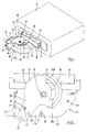
- the present embodiment is provided with a male connector M and a female connector F capable of fitting mutually together, the female connector F having a lever 20 attached thereto.
- the male connector M is provided with a male housing 11 provided in a unified manner on a specified side face of an apparatus 10.
- a hood 12 which has an oblong shape with respect to the front, is formed on the male housing 11.
- Male terminal fittings (not shown), which are connected to an electrical circuit within the apparatus 10, are housed within the male housing 11 in a manner whereby tips thereof protrude into the hood 12.
- the female connector F is formed from a flat block-shaped female housing 16 that can be fitted into the hood 12 of the male housing 11, and a cover 17 that covers a posterior face of the female housing 16.
- Female terminal fittings (not shown) are housed within the female housing 16, electric wires which are attached thereto and protrude from a posterior face of the female housing 16 are passed through the cover 17 and are led, in one bundle, towards one direction from a wire exit hole 18.
- the lever 20 is attached to the female connector F.
- This lever 20 has a bifurcated shape whereby tips of a pair of arms 21 thereof, these arms 21 having disk-shaped base ends 22, are joined by an operating member 23.
- the lever 20 is attached so as to straddle the cover 17 from the exterior.
- the base ends 22 of the arms 21 are supported by axles 25 formed in both side faces of the cover 17.
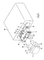
- the lever 20 can be pivoted between a starting position (shown in Figure 1) and an ending position (shown in Figure 6).
- the lever 20 is maintained in the starting position by means of semi-retaining protrusions 27, which protrude from the cover 17 and fit into circular semi-retaining holes 26 which open into the lever 20.
- the lever 20 is maintained in the ending position by means of square main retaining protrusions 28 fitting into main retaining holes 29 of the cover 17.
- Cam grooves 30, which have a specified curved shape, are formed in the base ends 22 of the arms 21 of the lever 20, and follower pins 32 protrude from upper and lower faces of the hood 12 of the male housing 11. These follower pins 32 fit into the cam grooves 30.
- first ribs 40 protrude from outer circumference edges of the base ends 22 of the arms 21 of the lever 20, at locations opposite the portions of the lever 20 which are between ending position sides 30B of the cam grooves 30 and the axes 25.
- first ribs 40 face the posterior relative to the direction of insertion of the female housing 16, and protruding edges 41 of the first ribs 40 form a unified face with a ceiling face 17A of the cover 17.
- Second ribs 45 are formed on portions of left and right side edges of the ceiling face 17A of the cover 17, at locations corresponding to the position in which the first ribs 40 are located when the lever 20 has been rotated to the ending position.
- the left and right side edges of the ceiling face 17A of the cover 17 have rounded-off comers.
- the second ribs 45 which are formed at a right angle to the left and right side edges, have angled comers extending to the location where the comers of the side edges would be if they were not rounded off.
- ceiling-face ends i.e., the opposite ends to the angled comers
- side-face ends i.e. the opposite ends to the angled corners
- the follower pins 32 are moved towards the ending position sides 30B of the cam grooves 30 while the lever 20 is being pivoted towards the end position.
- the main retaining protrusions 28 fit into the main retaining holes 29, thereby locking the two housings.
- the corresponding male and female terminal fittings are maintained in a state whereby they make contact correctly.
- the first ribs 40 of the lever 20 and the second ribs 45 of the cover 17 are aligned above and below in a straight line. This allows one to verify that the lever 20 has been correctly rotated to the ending position. If the markers are viewed from the front (from the direction shown by the arrow X in Figure 6), the protruding edges 41 of the first ribs 40 are aligned vertically with the protruding edges 46 (the ceiling face ends) of the second ribs 45.
- the markers are viewed from the side (from the direction shown by the arrow Y in Figure 6), the left sides of the protruding edges 41 of the first ribs 40 are aligned vertically with the protruding edges 46 (the ceiling face ends) of the second ribs 45. If the markers are viewed from above (from the direction shown by the arrow Z in Figure 6), only a side edge 42 of one of the first ribs 40 is visible. In this manner, one can verify that the ribs 40 and the 45 are aligned.
- the shape of the two ribs 40 and 45 allows one to view the markers from three directions, (from the front, the side, and above), so as to verify whether the markers have been aligned.
- the two ribs 40 and 45 are formed so as to be housed within the outer form of the cover 17. Consequently, foreign objects do not strike against them, and damage thereto is prevented.
- a second embodiment of the present invention is described below with the aid of Figure 7.
- This second embodiment differs from the first in that second ribs 50 located on the cover 17 have a differing shape. That is, protruding portions 51 (the ends of the second ribs 50 opposite the angled ends thereof) located on the ceiling face 17A of the cover 17 protrude outwards for a specified distance relative to the first ribs 40 of the lever 20.
- the side edges 42 of the first ribs 40 are aligned horizontally with side edges 52 of the protruding portions 51 of the second ribs 50. Consequently, one can verify that the ribs 40 and the 50 are aligned. That is, the ribs 50 are not hidden. Instead, both the ribs 40 and 50 can be seen while their alignment is being verified. Consequently, a more reliable judgement can be made.
Landscapes
- Details Of Connecting Devices For Male And Female Coupling (AREA)
Abstract
Description
Claims (11)
- A lever-type connector assembly comprising a pair of mutually engageable connectors (M,F), a lever (20) pivotably supported on one of the connectors (F) and defining a cam, and the other of said connectors (M) defining a follower (32) engageable with said cam such that pivoting of said lever (20) to an end position draws said connectors (M,F) fully together, wherein said lever and said one of said connectors include markers (40,45), said markers being aligned in the end position of said lever.
- A connector according to claim 1 wherein said one of said connectors (F) comprises a housing (16) and a cover therefor (17), and one of said markers (40,45) being provided on said cover.
- A connector according to claim 1 or claim 2 wherein said markers (40,45) comprise outwardly extending rib, having a long axis and a short axis, said ribs being aligned in said end position.
- A connector according to claim 3 wherein said ribs (40,45) are aligned on the long axis thereof in said end position.
- A connector according to claim 3 or claim 4 wherein said ribs (40,45) are immediately adjacent in said end position.
- A connector according to any of claims 3-5 wherein said ribs (40,45) have the same thickness.
- A connector according to any of claims 3-6 wherein said ribs (40,45) have different heights so as to be both visible when viewed on end.
- A connector according to any of claims 3-7 wherein the long axis of said ribs (40,45) is parallel to the axis of said lever (20).
- A connector according to any of claims 3-8 wherein said lever (20) has arms (21) extending on either side of said one of said connectors (F), the arms (21) being pivoted to said one of said connectors on a common pivot axis, and a said rib (40) being provided on each of said arms (21).
- A connector according to claim 9 wherein said connectors (M,F) have a fitting axis, and in the end position said ribs (40,45) are aligned and perpendicular to said fitting axis.
- A connector according to any preceding claim wherein one of said markers (40), the pivot axis of said lever (20) and said follower (32) are aligned in said end position.
Applications Claiming Priority (2)
| Application Number | Priority Date | Filing Date | Title |
|---|---|---|---|
| JP2000244065 | 2000-08-11 | ||
| JP2000244065A JP3603760B2 (en) | 2000-08-11 | 2000-08-11 | Lever type connector |
Publications (3)
| Publication Number | Publication Date |
|---|---|
| EP1180827A2 true EP1180827A2 (en) | 2002-02-20 |
| EP1180827A3 EP1180827A3 (en) | 2002-12-11 |
| EP1180827B1 EP1180827B1 (en) | 2007-11-14 |
Family
ID=18734809
Family Applications (1)
| Application Number | Title | Priority Date | Filing Date |
|---|---|---|---|
| EP01305194A Expired - Lifetime EP1180827B1 (en) | 2000-08-11 | 2001-06-14 | Lever type connector |
Country Status (4)
| Country | Link |
|---|---|
| US (1) | US6471527B2 (en) |
| EP (1) | EP1180827B1 (en) |
| JP (1) | JP3603760B2 (en) |
| DE (1) | DE60131335T2 (en) |
Cited By (2)
| Publication number | Priority date | Publication date | Assignee | Title |
|---|---|---|---|---|
| CN107710520A (en) * | 2015-07-08 | 2018-02-16 | 住友电装株式会社 | The connector of wire cover and live line lid |
| EP3316413A4 (en) * | 2015-08-10 | 2019-02-27 | Sumitomo Wiring Systems, Ltd. | CONNECTOR WITH WIRE COVER |
Families Citing this family (32)
| Publication number | Priority date | Publication date | Assignee | Title |
|---|---|---|---|---|
| JP3987737B2 (en) * | 2002-02-26 | 2007-10-10 | 住友電装株式会社 | Lever type connector |
| JP3987736B2 (en) | 2002-02-26 | 2007-10-10 | 住友電装株式会社 | Lever type connector |
| JP2003249309A (en) | 2002-02-26 | 2003-09-05 | Sumitomo Wiring Syst Ltd | Split connector |
| JP2003249310A (en) * | 2002-02-26 | 2003-09-05 | Sumitomo Wiring Syst Ltd | Split connector |
| US7342894B2 (en) * | 2002-04-03 | 2008-03-11 | Qualcomm Incorporated | System and method for transparent Mobile IP registration within PPP negotiation |
| US7590408B2 (en) * | 2002-04-03 | 2009-09-15 | Qualcomm Incorporated | Systems and methods for early determination of network support for mobile IP |
| US6971894B2 (en) * | 2004-03-31 | 2005-12-06 | Jst Corporation | Dual action mechanical assisted connector |
| US6899554B1 (en) | 2004-04-19 | 2005-05-31 | Jst Corporation | Dual action mechanical assisted connector |
| CN101023564A (en) * | 2004-08-13 | 2007-08-22 | Jst公司 | Lever action mechanical assist connector |
| JP4492449B2 (en) * | 2005-06-15 | 2010-06-30 | 住友電装株式会社 | Lever type connector |
| JP5009538B2 (en) * | 2006-02-02 | 2012-08-22 | 矢崎総業株式会社 | Lever type connector |
| US7329132B1 (en) | 2006-07-31 | 2008-02-12 | Yazaki North America, Inc. | Low-insertion force-lever connector for blind mating |
| NZ578028A (en) * | 2007-01-10 | 2012-08-31 | Smart Technologies Ulc | Participant response system with question authoring/editing facility |
| JP4697191B2 (en) | 2007-06-12 | 2011-06-08 | トヨタ自動車株式会社 | Electrical device connector structure and vehicle |
| JP4893596B2 (en) * | 2007-11-15 | 2012-03-07 | 住友電装株式会社 | connector |
| US7584686B2 (en) | 2007-11-26 | 2009-09-08 | Cheng Chang Tsai | Quick release mechanism for socket wrench |
| DE202008002111U1 (en) * | 2008-02-14 | 2009-06-25 | Weidmüller Interface GmbH & Co. KG | Bayable electronics housing with pin or socket strips |
| US7559779B1 (en) | 2008-05-14 | 2009-07-14 | Cinch Connectors, Inc. | Electrical connector |
| JP6335457B2 (en) * | 2013-09-17 | 2018-05-30 | 矢崎総業株式会社 | Lever type connector |
| US9583860B1 (en) * | 2015-11-24 | 2017-02-28 | Te Connectivity Corporation | Electrical connector with recordable position assurance |
| US9905953B1 (en) | 2016-09-30 | 2018-02-27 | Slobodan Pavlovic | High power spring-actuated electrical connector |
| JP6989715B2 (en) | 2018-02-26 | 2022-01-05 | ロイヤル プレシジョン プロダクツ,エルエルシー | Spring-loaded electrical connectors for high power applications |
| US10651586B2 (en) * | 2018-06-01 | 2020-05-12 | Tyco Electronics Brasil Ltda | Electrical connector with machine-readable graphic identifier |
| CN112930624B (en) | 2018-06-07 | 2023-10-03 | 皇家精密制品有限责任公司 | Electrical connector system with internal spring components |
| DE112020000424T5 (en) | 2019-01-15 | 2021-09-23 | Royal Precision Products, Llc | SHIELDED ELECTRIC CONNECTOR SYSTEM WITH INTERNAL SPRING ELEMENT |
| CN113508498B (en) | 2019-01-21 | 2025-03-18 | 皇家精密制品有限责任公司 | Bus system |
| JP7092712B2 (en) * | 2019-07-11 | 2022-06-28 | 矢崎総業株式会社 | Lever type connector |
| DE112020003846T5 (en) | 2019-09-09 | 2022-05-12 | Royal Precision Products Llc | CONNECTOR RECORDING SYSTEM WITH READABLE AND RECORDABLE MARKERS |
| US11721942B2 (en) | 2019-09-09 | 2023-08-08 | Eaton Intelligent Power Limited | Connector system for a component in a power management system in a motor vehicle |
| JP7319184B2 (en) * | 2019-12-13 | 2023-08-01 | 矢崎総業株式会社 | Incomplete mating detection structure and connector |
| JP7734183B2 (en) | 2020-07-29 | 2025-09-04 | イートン インテリジェント パワー リミテッド | Connector systems including interlocking systems |
| JP2023069707A (en) * | 2021-11-08 | 2023-05-18 | 株式会社オートネットワーク技術研究所 | lever type connector |
Family Cites Families (7)
| Publication number | Priority date | Publication date | Assignee | Title |
|---|---|---|---|---|
| US5238417A (en) * | 1990-12-15 | 1993-08-24 | Yazaki Corporation | Connector with a lever |
| JP2772309B2 (en) | 1993-03-17 | 1998-07-02 | 矢崎総業株式会社 | Lever connection type connector |
| US5888081A (en) * | 1996-08-08 | 1999-03-30 | Sumitomo Wiring Systems Inc. | Lever connector |
| US5810612A (en) * | 1996-08-26 | 1998-09-22 | General Motors Corporation | Electrical connector with cam lock lever |
| DE19844693A1 (en) * | 1998-09-29 | 2000-03-30 | Delphi Automotive Systems Gmbh | Two part electrical connector |
| EP1024559A3 (en) * | 1999-01-26 | 2001-08-08 | VEAM S.r.L. | Handle operated power connector |
| JP2001035591A (en) * | 1999-07-16 | 2001-02-09 | Sumitomo Wiring Syst Ltd | Lever connector |
-
2000
- 2000-08-11 JP JP2000244065A patent/JP3603760B2/en not_active Expired - Fee Related
-
2001
- 2001-06-14 DE DE60131335T patent/DE60131335T2/en not_active Expired - Lifetime
- 2001-06-14 EP EP01305194A patent/EP1180827B1/en not_active Expired - Lifetime
- 2001-07-11 US US09/902,171 patent/US6471527B2/en not_active Expired - Fee Related
Cited By (2)
| Publication number | Priority date | Publication date | Assignee | Title |
|---|---|---|---|---|
| CN107710520A (en) * | 2015-07-08 | 2018-02-16 | 住友电装株式会社 | The connector of wire cover and live line lid |
| EP3316413A4 (en) * | 2015-08-10 | 2019-02-27 | Sumitomo Wiring Systems, Ltd. | CONNECTOR WITH WIRE COVER |
Also Published As
| Publication number | Publication date |
|---|---|
| US20020019156A1 (en) | 2002-02-14 |
| EP1180827B1 (en) | 2007-11-14 |
| JP3603760B2 (en) | 2004-12-22 |
| DE60131335T2 (en) | 2008-09-11 |
| JP2002056934A (en) | 2002-02-22 |
| US6471527B2 (en) | 2002-10-29 |
| DE60131335D1 (en) | 2007-12-27 |
| EP1180827A3 (en) | 2002-12-11 |
Similar Documents
| Publication | Publication Date | Title |
|---|---|---|
| US6471527B2 (en) | Lever-type connector with engagement markers | |
| EP0510229B1 (en) | An electrical connector with positive latch | |
| JP5511464B2 (en) | Board connection connector fitting confirmation structure | |
| EP1091450B1 (en) | Connector | |
| US6802746B2 (en) | Electrical connector with terminal position assurance system | |
| JPH06302353A (en) | Low insertion force connector | |
| EP1158624B1 (en) | Lever-type connector | |
| EP0848458A1 (en) | Connector with engagement detection means | |
| US6575775B2 (en) | Connector with shorting terminal | |
| US5238417A (en) | Connector with a lever | |
| JP3400224B2 (en) | Electrical connector | |
| CN100416931C (en) | plug | |
| EP1126556A2 (en) | Connector provided with a cover | |
| EP1168518A2 (en) | Connector | |
| JPH10302895A (en) | Connection device with modular connector | |
| JP2002289302A (en) | Electrical connector | |
| EP0999614A2 (en) | Electrical connector provided with a locking member | |
| JP2022527722A (en) | Connector position guarantee member | |
| JPH11176517A (en) | Combination connector and connection structure of combination connector and casing | |
| JP4246058B2 (en) | Electrical connector | |
| US20250038456A1 (en) | Connector and connector assembly | |
| JP3725337B2 (en) | Connector device | |
| JPH09147988A (en) | Connector with half mating detection function | |
| JP2003115356A (en) | Lever type connector | |
| JP3868882B2 (en) | Connector with mating guarantee parts and mating guarantee parts |
Legal Events
| Date | Code | Title | Description |
|---|---|---|---|
| PUAI | Public reference made under article 153(3) epc to a published international application that has entered the european phase |
Free format text: ORIGINAL CODE: 0009012 |
|
| 17P | Request for examination filed |
Effective date: 20010629 |
|
| AK | Designated contracting states |
Kind code of ref document: A2 Designated state(s): AT BE CH CY DE DK ES FI FR GB GR IE IT LI LU MC NL PT SE TR |
|
| AX | Request for extension of the european patent |
Free format text: AL;LT;LV;MK;RO;SI |
|
| PUAL | Search report despatched |
Free format text: ORIGINAL CODE: 0009013 |
|
| AK | Designated contracting states |
Kind code of ref document: A3 Designated state(s): AT BE CH CY DE DK ES FI FR GB GR IE IT LI LU MC NL PT SE TR |
|
| AX | Request for extension of the european patent |
Free format text: AL;LT;LV;MK;RO;SI |
|
| AKX | Designation fees paid |
Designated state(s): DE |
|
| 17Q | First examination report despatched |
Effective date: 20061108 |
|
| GRAP | Despatch of communication of intention to grant a patent |
Free format text: ORIGINAL CODE: EPIDOSNIGR1 |
|
| RIN1 | Information on inventor provided before grant (corrected) |
Inventor name: YAMASHITA, KAZUNORI,C/O SUMITOMO WIRING SYSTEMS, L Inventor name: FUKAMACHI, MAKOTO,C/O SUMITOMO WIRING SYSTEMS, LTD |
|
| GRAS | Grant fee paid |
Free format text: ORIGINAL CODE: EPIDOSNIGR3 |
|
| GRAA | (expected) grant |
Free format text: ORIGINAL CODE: 0009210 |
|
| AK | Designated contracting states |
Kind code of ref document: B1 Designated state(s): DE |
|
| REF | Corresponds to: |
Ref document number: 60131335 Country of ref document: DE Date of ref document: 20071227 Kind code of ref document: P |
|
| PLBE | No opposition filed within time limit |
Free format text: ORIGINAL CODE: 0009261 |
|
| STAA | Information on the status of an ep patent application or granted ep patent |
Free format text: STATUS: NO OPPOSITION FILED WITHIN TIME LIMIT |
|
| 26N | No opposition filed |
Effective date: 20080815 |
|
| PGFP | Annual fee paid to national office [announced via postgrant information from national office to epo] |
Ref country code: DE Payment date: 20120607 Year of fee payment: 12 |
|
| REG | Reference to a national code |
Ref country code: DE Ref legal event code: R119 Ref document number: 60131335 Country of ref document: DE Effective date: 20140101 |
|
| PG25 | Lapsed in a contracting state [announced via postgrant information from national office to epo] |
Ref country code: DE Free format text: LAPSE BECAUSE OF NON-PAYMENT OF DUE FEES Effective date: 20140101 |