EP1180824A2 - Plug for a connector arrangement - Google Patents
Plug for a connector arrangement Download PDFInfo
- Publication number
- EP1180824A2 EP1180824A2 EP01118678A EP01118678A EP1180824A2 EP 1180824 A2 EP1180824 A2 EP 1180824A2 EP 01118678 A EP01118678 A EP 01118678A EP 01118678 A EP01118678 A EP 01118678A EP 1180824 A2 EP1180824 A2 EP 1180824A2
- Authority
- EP
- European Patent Office
- Prior art keywords
- plug
- housing
- mating
- locking latch
- connector
- Prior art date
- Legal status (The legal status is an assumption and is not a legal conclusion. Google has not performed a legal analysis and makes no representation as to the accuracy of the status listed.)
- Withdrawn
Links
Images
Classifications
-
- H—ELECTRICITY
- H01—ELECTRIC ELEMENTS
- H01R—ELECTRICALLY-CONDUCTIVE CONNECTIONS; STRUCTURAL ASSOCIATIONS OF A PLURALITY OF MUTUALLY-INSULATED ELECTRICAL CONNECTING ELEMENTS; COUPLING DEVICES; CURRENT COLLECTORS
- H01R13/00—Details of coupling devices of the kinds covered by groups H01R12/70 or H01R24/00 - H01R33/00
- H01R13/62—Means for facilitating engagement or disengagement of coupling parts or for holding them in engagement
- H01R13/627—Snap or like fastening
Definitions
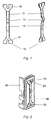
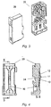
- the metal member 10 is secured to a side wall of a connector housing part 20 of a connector assembly.
- the metal member extends in a direction which is essentially parallel to the longitudinal axis of the housing part 20 and to the axis of mating of the plug and mating plug.
- a recess or indentation 21 is formed in the side wall of the housing part 20 in such a manner that it can accommodate the metal member 10.
- the locking latch positioned in the housing recess 21, the recesses 14 and 15 cooperate with projections 22, 23 extending from the sidewall to secure the metal member to the housing part 20.
- the fastening of the locking latch to the connector housing can also be achieved by means of ultrasonic or heat caulking.
Landscapes
- Details Of Connecting Devices For Male And Female Coupling (AREA)
- Connector Housings Or Holding Contact Members (AREA)
Abstract
Description
Claims (10)
- A plug for a connector assembly, consisting of a plug and an accompanying mating plug, the plug comprising:characterised in that:a connector housing;a locking latch which is arranged on the housing, and which, during a mating of the plug and the mating plug, comes into contact with a part of the mating plug;
the locking latch is designed as a separate part (10) which can be connected to the housing. - The plug according to claim 1, characterised in that the locking latch is made of a material which has greater strength characteristics than the material of the housing.
- The plug according to claim 1 or 2, characterised in that the connector housing is made from a synthetic material.
- The plug according to one of claims 1 to 3, characterised in that the locking latch is a metal member (10) with a locking projection (11) projecting therefrom.
- The plug according to one of claims 1 to 4, characterised in that the locking latch is arranged on an outside wall of the housing and comprises a fastening device (14, 15) for fastening to the housing wall.
- The plug according claim 5, characterised in that the side wall of the housing has a recess (24) which extends under part of the locking latch whereby the locking latch is moved into the recess (24) in a resilient manner when the mating plug is mated to the plug.
- The plug according to one of claims 5 or 6, characterised in that the fastening device (14, 15) comprises a recess in the metal member (10), which can be latched to a projection (22, 23) extending from the housing.
- The plug according to one of claims 5 to 7, characterised in that the side wall of the housing comprises indentations (21), to accommodate the locking latch.
- The plug according to at least claim 4, characterised in that the metal member extends in the direction parallel to the axis of a mating of the plug with the mating plug.
- Connector arrangement, consisting of a plug according to one of claims 1 to 9 and an accompanying mating plug.
Applications Claiming Priority (2)
| Application Number | Priority Date | Filing Date | Title |
|---|---|---|---|
| DE10038684 | 2000-08-08 | ||
| DE10038684 | 2000-08-08 |
Publications (2)
| Publication Number | Publication Date |
|---|---|
| EP1180824A2 true EP1180824A2 (en) | 2002-02-20 |
| EP1180824A3 EP1180824A3 (en) | 2003-11-19 |
Family
ID=7651724
Family Applications (1)
| Application Number | Title | Priority Date | Filing Date |
|---|---|---|---|
| EP01118678A Withdrawn EP1180824A3 (en) | 2000-08-08 | 2001-08-03 | Plug for a connector arrangement |
Country Status (4)
| Country | Link |
|---|---|
| EP (1) | EP1180824A3 (en) |
| CN (1) | CN1214495C (en) |
| BR (1) | BR0103213A (en) |
| MX (1) | MXPA01007969A (en) |
Families Citing this family (1)
| Publication number | Priority date | Publication date | Assignee | Title |
|---|---|---|---|---|
| CN111355103B (en) * | 2018-12-21 | 2021-09-28 | 沈阳新松机器人自动化股份有限公司 | Quartzy first fastener of robot router |
Family Cites Families (6)
| Publication number | Priority date | Publication date | Assignee | Title |
|---|---|---|---|---|
| US3101230A (en) * | 1961-06-26 | 1963-08-20 | Bausch Ewald | Locking and extracting means for can-enclosed units |
| US3544951A (en) * | 1968-06-28 | 1970-12-01 | Deutsch Co Elec Comp | Coupling with deflectable arms |
| FR2453513A1 (en) * | 1979-04-06 | 1980-10-31 | Cit Alcatel | CONNECTOR-DISTRIBUTOR |
| FR2753573B1 (en) * | 1996-09-16 | 1998-11-27 | F R B Connectron | ELECTRICAL CONNECTOR COMPRISING A BASE AND A PLUG |
| US5762514A (en) * | 1997-02-24 | 1998-06-09 | The Whitaker Corporation | Connector with affixable latch member |
| FR2779780B1 (en) * | 1998-06-11 | 2000-08-18 | Framatome Connectors France | PREDOMINANT LOCKING DEVICE |
-
2001
- 2001-08-03 EP EP01118678A patent/EP1180824A3/en not_active Withdrawn
- 2001-08-06 BR BR0103213A patent/BR0103213A/en not_active Application Discontinuation
- 2001-08-07 MX MXPA01007969 patent/MXPA01007969A/en unknown
- 2001-08-08 CN CN 01132575 patent/CN1214495C/en not_active Expired - Lifetime
Also Published As
| Publication number | Publication date |
|---|---|
| EP1180824A3 (en) | 2003-11-19 |
| BR0103213A (en) | 2002-07-23 |
| CN1337763A (en) | 2002-02-27 |
| CN1214495C (en) | 2005-08-10 |
| MXPA01007969A (en) | 2004-01-29 |
Similar Documents
| Publication | Publication Date | Title |
|---|---|---|
| US5380220A (en) | Connector | |
| JP3364837B2 (en) | Electrical connector having integral latch and strain relief device | |
| JP4372138B2 (en) | Electrical contact | |
| EP0774801A2 (en) | Electrical terminal with protected locking lance and a connector therefor | |
| EP2642598A1 (en) | Electric terminal | |
| KR101115826B1 (en) | Connection terminal | |
| EP1009063A2 (en) | A connector | |
| EP0778636A1 (en) | Electrical connector with terminal locking means | |
| JP2022064312A (en) | Electric terminal | |
| CN101764312B (en) | Electric connector | |
| EP0795930B1 (en) | High contact force pin-receiving electrical contact | |
| JPH0722079A (en) | Waterproof pressure welding connector | |
| US20030032321A1 (en) | Sealed connector | |
| CN102742089A (en) | Socket housing | |
| US8087945B2 (en) | Electric connector with a dust cover | |
| CN113826283A (en) | Connecting Devices and Connectors | |
| CN111952794B (en) | Connector housings, mating connector housings and systems | |
| JP2006511918A (en) | Flexible cable electrical connector | |
| US6033262A (en) | Contact spring | |
| EP1134848B1 (en) | A connector and a set of terminal fittings | |
| JPH11260458A (en) | Waterproof connector and method of assembling the waterproof connector | |
| JPH06260238A (en) | Connecting terminal | |
| US20250279593A1 (en) | Electric cable or electric wire provided with a plug contour for directly plugging into a mating plug | |
| EP3671959A1 (en) | Connector | |
| KR20250117826A (en) | Plug connector inserts for electrical plug connectors |
Legal Events
| Date | Code | Title | Description |
|---|---|---|---|
| PUAI | Public reference made under article 153(3) epc to a published international application that has entered the european phase |
Free format text: ORIGINAL CODE: 0009012 |
|
| AK | Designated contracting states |
Kind code of ref document: A2 Designated state(s): AT BE CH CY DE DK ES FI FR GB GR IE IT LI LU MC NL PT SE TR |
|
| AX | Request for extension of the european patent |
Free format text: AL;LT;LV;MK;RO;SI |
|
| PUAL | Search report despatched |
Free format text: ORIGINAL CODE: 0009013 |
|
| AK | Designated contracting states |
Kind code of ref document: A3 Designated state(s): AT BE CH CY DE DK ES FI FR GB GR IE IT LI LU MC NL PT SE TR |
|
| AX | Request for extension of the european patent |
Extension state: AL LT LV MK RO SI |
|
| 17P | Request for examination filed |
Effective date: 20040414 |
|
| 17Q | First examination report despatched |
Effective date: 20040614 |
|
| AKX | Designation fees paid |
Designated state(s): AT BE CH CY DE DK ES FI FR GB GR IE IT LI LU MC NL PT SE TR |
|
| STAA | Information on the status of an ep patent application or granted ep patent |
Free format text: STATUS: THE APPLICATION IS DEEMED TO BE WITHDRAWN |
|
| 18D | Application deemed to be withdrawn |
Effective date: 20041228 |