EP1180720A1 - Calibration patches - Google Patents
Calibration patches Download PDFInfo
- Publication number
- EP1180720A1 EP1180720A1 EP01202868A EP01202868A EP1180720A1 EP 1180720 A1 EP1180720 A1 EP 1180720A1 EP 01202868 A EP01202868 A EP 01202868A EP 01202868 A EP01202868 A EP 01202868A EP 1180720 A1 EP1180720 A1 EP 1180720A1
- Authority
- EP
- European Patent Office
- Prior art keywords
- patches
- photographic element
- exposure
- reference calibration
- patch
- Prior art date
- Legal status (The legal status is an assumption and is not a legal conclusion. Google has not performed a legal analysis and makes no representation as to the accuracy of the status listed.)
- Withdrawn
Links
- 230000007547 defect Effects 0.000 claims abstract description 27
- 230000001747 exhibiting effect Effects 0.000 claims abstract description 3
- 229910052709 silver Inorganic materials 0.000 claims description 4
- 239000004332 silver Substances 0.000 claims description 4
- -1 silver halide Chemical class 0.000 claims description 3
- 230000000694 effects Effects 0.000 abstract description 17
- 238000005259 measurement Methods 0.000 description 21
- 238000000034 method Methods 0.000 description 12
- 238000005286 illumination Methods 0.000 description 7
- 238000010586 diagram Methods 0.000 description 6
- 230000000875 corresponding effect Effects 0.000 description 5
- 238000011109 contamination Methods 0.000 description 4
- 238000012864 cross contamination Methods 0.000 description 3
- 238000013461 design Methods 0.000 description 3
- 238000001035 drying Methods 0.000 description 3
- 238000000149 argon plasma sintering Methods 0.000 description 2
- 238000003491 array Methods 0.000 description 2
- 238000012937 correction Methods 0.000 description 2
- 238000011161 development Methods 0.000 description 2
- 239000000463 material Substances 0.000 description 2
- 230000007246 mechanism Effects 0.000 description 2
- 230000003287 optical effect Effects 0.000 description 2
- 238000012856 packing Methods 0.000 description 2
- 230000035945 sensitivity Effects 0.000 description 2
- 238000011282 treatment Methods 0.000 description 2
- 241001479434 Agfa Species 0.000 description 1
- 238000012935 Averaging Methods 0.000 description 1
- 108700012928 MAPK14 Proteins 0.000 description 1
- 101000879966 Mus musculus Eosinophil cationic protein 2 Proteins 0.000 description 1
- 102000012500 Proto-Oncogene Proteins c-crk Human genes 0.000 description 1
- BQCADISMDOOEFD-UHFFFAOYSA-N Silver Chemical compound [Ag] BQCADISMDOOEFD-UHFFFAOYSA-N 0.000 description 1
- 235000010724 Wisteria floribunda Nutrition 0.000 description 1
- 238000001311 chemical methods and process Methods 0.000 description 1
- 239000011248 coating agent Substances 0.000 description 1
- 238000000576 coating method Methods 0.000 description 1
- 230000002596 correlated effect Effects 0.000 description 1
- 230000002950 deficient Effects 0.000 description 1
- 230000008030 elimination Effects 0.000 description 1
- 238000003379 elimination reaction Methods 0.000 description 1
- 238000003475 lamination Methods 0.000 description 1
- 230000007935 neutral effect Effects 0.000 description 1
- 238000012545 processing Methods 0.000 description 1
- 230000005855 radiation Effects 0.000 description 1
- XLYOFNOQVPJJNP-UHFFFAOYSA-N water Substances O XLYOFNOQVPJJNP-UHFFFAOYSA-N 0.000 description 1
Images

Classifications
-
- G—PHYSICS
- G03—PHOTOGRAPHY; CINEMATOGRAPHY; ANALOGOUS TECHNIQUES USING WAVES OTHER THAN OPTICAL WAVES; ELECTROGRAPHY; HOLOGRAPHY
- G03B—APPARATUS OR ARRANGEMENTS FOR TAKING PHOTOGRAPHS OR FOR PROJECTING OR VIEWING THEM; APPARATUS OR ARRANGEMENTS EMPLOYING ANALOGOUS TECHNIQUES USING WAVES OTHER THAN OPTICAL WAVES; ACCESSORIES THEREFOR
- G03B27/00—Photographic printing apparatus
- G03B27/72—Controlling or varying light intensity, spectral composition, or exposure time in photographic printing apparatus
- G03B27/73—Controlling exposure by variation of spectral composition, e.g. multicolor printers
Definitions
- the present invention relates to photography and more particularly to the arrangement of reference calibration patches on photographic elements for use in photofinishing.
- the need is met according to the present invention by providing an arrangement of reference calibration patches produced by a sequence of exposures on a photographic element, the photographic element exhibiting linear defects in a predominant direction, that are arranged in a two dimensional array and exposures are assigned to the reference calibration patches in the array such that nearest neighbors in the predominant direction are not nearest neighbors in the exposure sequence, whereby the effects of a linear defect are reduced; and the maximum number of steps in the exposure sequence between a reference calibration patch and that of its nearest neighbors in any direction is less than a predetermined number, whereby the effects of flare are reduced.
- the reference calibration patch arrangement of the present invention has the advantages that the impact of exposure flare in exposing the patches, the impact of flare in a scanner used to read the patches, and the effect of loss of data to extended linear defects is reduced, while minimizing the rectangular area occupied by the reference calibration patch arrangement on the photographic element.
- sequence of reference calibration patches can be arranged to efficiently use space on the film.
- the arrangement of the reference calibration patches according to the present invention also enables greater robustness of the resulting reference calibration to data loss induced by the presence of extended linear defects, such as streaks, scratches, etc.
- the sequence of reference calibration patches used in this nvention could be a plurality of neutral patches, colored patches, or any combination thereof.
- a photographic element includes at least a base with a photosensitive layer that is sensitive to light to produce a developable latent image.
- the photosensitive layer may contain conventional silver halide chemistry, or other photosensitive materials such as thermal or pressure developable chemistries. It can have a transparent base, a reflective base, or a base with a magnetically sensitive coating.
- the photographic element can be processed through standard chemical processes, including but not limited to Kodak Processes C-41 and its variants, ECN-2, VNF-1, ECP-2 and its variants, D-96, D-97, E-4, E-6, K-14, R-3, and RA-2SM, or RA-4; Fuji Processes CN-16 and its variants, CR-6, CP-43FA, CP-47L, CP-48S, RP-305, RA-4RT; Agfa MSC 100/101/200 Film and Paper Processes, Agfacolor Processes 70, 71, 72 and 94, Agfachrome Processes 44NP and 63; and Konica Processes CNK-4, CPK-2-22, DP, and CRK-2, and Konica ECOJET HQA-N, HQA-F, and HQA-P Processes.
- Kodak Processes C-41 and its variants ECN-2, VNF-1, ECP-2 and its variants, D-96, D-97
- the photographic element can be processed using alternate processes such as apparently dry processes that may retain some or all of the developed silver or silver halide in the element or that may include lamination and an appropriate amount of water added to swell the photographic element.
- the photographic element can also be processed using dry processes that may include thermal or high pressure treatment.
- the processing may also include a combination of apparently dry, dry, and traditional wet processes. Examples of suitable alternate and dry processes include the processes disclosed in: US Serial Nos.
- the response of a photographic element is typically linear in log exposure over a wide range of exposures.
- the effect of cross-contamination of reference calibration patches having different exposures in proximity to each other is clearly lessened if the exposure levels of nearby patches are nearby in exposure ratio or equivalent in log exposure.
- the intensity of stray light due to such mechanisms as optical flare from an illumination system or in-film light scattering, falls off continuously with distance.
- the closer two patches are in their desired illumination level the more closely the patches may be placed before unacceptable exposure occurs at all and the smaller any zone within a patch of unacceptable contamination will be.
- the closer two patches are in their desired illumination level at a given patch spacing the lower the ratio of inadvertent to desired exposure at any point becomes.
- Reference calibration patches created in a system with significant stray light can be used so long as they are sufficiently large or widely enough separated to accommodate subsequent measurement in a portion that has an acceptable level of inadvertent exposure from other, typically only neighboring, patches.
- the dominant effect is from light transmitted through a lower density patch 514 (resulting from development of a patch receiving a lower exposure), causing inadvertent additional illumination of sensors intended to receive radiation in an area 518, some of which are intended to be measuring a higher density patch 512 (resulting from development of a patch receiving a higher exposure).
- a patch is large enough so that the limited range of these sources of contamination does not affect data taken near the center of a patch and the central area is sufficiently large to provide adequate data for statistical treatments, accurate measurements may still be obtained.
- the patches be larger and closer together rather than smaller and more widely separated.
- a typical prior art step tablet arrangement with a sequence of rectangular patches juxtaposed in a linear arrangement, accomplishes the goals of reducing the effects of exposure and measurement errors by placing exposures in a monotonically increasing sequence from the lowest exposure at one end to the highest exposure at the other.
- This arrangement is optimal from exposure and measurement standpoints in that the exposure and measurement effects are made as small as practicable for a given set of desired exposures and densities by minimizing the exposure ratios and density differences between the steps.
- the extent of contamination effects in exposure and measurement is factored in, a portion of each step edge will be outside an acceptable range for measurement error. Additionally, the presence of measurement noise and random nonuniformity in density requires that a number of measurements be averaged.
- Elimination of unacceptable data and use of multiple data points for averaging implies a minimum size requirement for a step.
- the problem with the traditional step tablet arrangement is that given the minimum size for each step, the tablet becomes too long to conveniently fit on a conventional film strip.
- Reference calibration patch arrangements that are arranged in two dimensional arrays are more efficient in using the space on a film strip, but such arrays admit a possibility of having adjacent patches that are undesirably far apart in the exposure sequence. For example, if a long sequence of patches is desired but fewer patches can be fit into a desired length, the sequence of patches can be rearranged into a two dimensional array comprising a collection of linear subarrays, with each subarray comprising a segment of the sequence. This may be accomplished in a variety of ways.
- One way is to use a small number of longer segments. However, such an arrangement can place patches adjacent to each other that are widely separated in the sequence. This could lead to a need for a greater spacing between the linear subarrays than within a linear subarray to avoid exposure or measurement flare artifacts, which would in turn increase the area needed on the photographic element.
- Another way is to use a larger number of shorter segments. This reduces the number of steps between neighboring patches in the array and allows for a lesser spacing between the linear subarrays.
- the subarrays can be placed such that the patches form a hexagonal close packed array, with equal center-to-center distance between all nearest neighbor patches. This achieves a closer packing than a rectangular array, and improves the overlap between the flare regions around each patch that is useful in reducing scanning flare effects.
- the dominant direction of extended defects such as streaks and scratches tends to be along the length of a film strip.
- Such a defect could corrupt the data from multiple patches aligned with the length of the strip.
- Ability to detect, eliminate, and replace defective data in the generation of reference calibration tables can be enhanced by arranging patches so that a single linear defect cannot corrupt the data from a subset of patches that form a contiguous segment of the exposure sequence. Additionally, arrangements that reduce the number of patches aligned with the length of the strip would lead to less data loss from such a linear defect.
- the optimal solution from the standpoint of minimizing the effects of linear defects alone would be to have one patch in each row, that is, to have the patches aligned in a linear array across the film strip. However, in a film strip, the widthwise dimension is shorter than the lengthwise direction, so this solution is impractical.
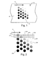
- a photographic element 10 for example, a strip of color negative film with a perforation 12 is exposed with a two-dimensional array of reference calibration patches 14 representing a sequence of exposures.
- the photographic element 10 exhibits linear defects, such as film scratches, in a predominant direction indicated by arrow A.
- This array of reference calibration patches is advantageously placed in an area of the film strip relative to the perforation analogously to placement of an ordinary image frame, as disclosed in co-pending patent application US Serial No. 09/635,496.
- the arrangement of these reference calibration patches, including specific locations of the patches within the array and assignment of exposures to these locations is the subject of the present invention.
- FIG. 2 an arrangement of 23 circular reference calibration patches is shown. Although circular patches are shown, other patch shapes, such as square, rectangular, and hexagonal can be employed. The patches are arranged on centers that form vertical columns with vertical offsets between each column to effect more efficient packing.
- the exposure sequence increases along diagonal paths starting with a first (or zero) exposure patch 200, followed by the next steps in the exposure sequence in order in the next diagonal group of patches 202, 204, and 206, followed by the next patch 208 at the start of the next diagonal group, and proceeding in likewise fashion up to the highest step 244 in the exposure sequence.
- a single linear defect 210 parallel to arrow A in the top row of patches will affect the reference calibration patches corresponding to the first, fourth and ninth steps in the sequence.
- a linear defect 212 in the second row will affect reference calibration patches corresponding to the third and eighth steps.
- the exposures of reference calibration patches affected by a single linear defect are separated by more than one step in the exposure sequence.
- the same two dimensional arrangement of reference calibration patches may have a different assignment of steps in the exposure sequence to the patches that further separates the patches in the sequence affected by a linear defect at the expense of having adjacent patches separated by a greater number of steps in parts of the array.
- the steps progress along vertical columns starting with a lowest exposure patch 300, followed by increasing exposures in the column 302, 304, 306, and 308, followed by the next exposure in patch 301 at the start of the next vertical column, and proceeding in likewise fashion up to the highest exposure patch 344 .
- a single linear defect 310 parallel to arrow A in the top row of patches will affect the reference calibration patches corresponding to the first, tenth, and nineteenth steps of the sequence.
- a linear defect 312 in the second row will affect the reference calibration patches corresponding to the sixth and fifteenth steps.
- the reference calibration patches affected by a single linear defect are more widely separated in the exposure sequence in this arrangement, however, some of the differences in steps in the exposure sequence of adjacent patches are also increased.
- neighboring patches 300 and 301 in Fig. 3 are separated by 5 steps, whereas the corresponding patches 200 and 204 in Fig. 2 are separated by 2 steps.
- the tighter spacing of exposure sequence steps in the corners of the array afforded by the arrangement in Fig. 2 can be advantageous in cases where more widely separated exposure ratios or developed densities form a portion of the exposure sequence in which case a lesser number of steps between adjacent patches would be desired.
- FIG. 4 an alternative arrangement of patches is illustrated which comprises the same number of patches as shown in Fig. 2 and Fig. 3 but arranged in a rectangular array with nine columns of patches.
- the exposures of the patches increase along vertical columns starting with a lowest exposure patch 400, followed by increasing exposures in patches 402 and 404 in the same vertical column, followed by the next exposures in patches 406 and 408 in the next vertical column, and proceeding in likewise fashion up to the highest exposure patch 444.
- sensitivity to stray light in exposure and measurement is reduced by placing similar patches closer and dissimilar spots more distant from each other.
- Sensitivity to extended linear defects is reduced by minimizing the number of measured spots that would be intersected by such a defect and by arranging exposures in each row so that the affected exposures are more widely separated. Constraints on the overall dimensions of an arrangement as well as tradeoffs between robustness to stray light and robustness to extended linear defects can lead to different arrangements that are consistent with these design principles.
Landscapes
- Physics & Mathematics (AREA)
- Spectroscopy & Molecular Physics (AREA)
- General Physics & Mathematics (AREA)
- Control Of Exposure In Printing And Copying (AREA)
- Projection-Type Copiers In General (AREA)
Abstract
Description
- The present invention relates to photography and more particularly to the arrangement of reference calibration patches on photographic elements for use in photofinishing.
- The use of a sequence of reference calibration patches exposed on a roll of film to enable better exposure control during optical printing is known in the art; see for example US Patent No. 5,767,983 issued June 16, 1998 to Terashita. The use of reference calibration patches has also been shown to be useful in determining correction values for scanned film data used in digital printing. See for example US Patent No. 5,667,944 issued September 16, 1997 to Reem et al., and US Patent No. 5,649,260 issued July 15, 1997 to Wheeler et al.
- Problems experienced with these reference calibration patches have included the occurrence of naturally arising artifacts in exposing the reference calibration patches onto the film, difficulties experienced in subsequent measurement of the patches on processed film, and data loss due to defects such as scratches or streaks in the images of the printed patches. To limit the area of film that is occupied by the reference calibration patches, it is desirable to expose as many reference calibration patches as possible onto the smallest area of film. In the exposure process, flare from high exposure reference calibration patches can affect the exposure of nearby patches, thereby affecting the intended exposure of the nearby patches. In the measurement process, flare can bias the accurate reading of the patch density, particularly in high density patches.
- There is a need therefore for an improved reference calibration patch arrangement that minimizes the problems noted above.
- The need is met according to the present invention by providing an arrangement of reference calibration patches produced by a sequence of exposures on a photographic element, the photographic element exhibiting linear defects in a predominant direction, that are arranged in a two dimensional array and exposures are assigned to the reference calibration patches in the array such that nearest neighbors in the predominant direction are not nearest neighbors in the exposure sequence, whereby the effects of a linear defect are reduced; and the maximum number of steps in the exposure sequence between a reference calibration patch and that of its nearest neighbors in any direction is less than a predetermined number, whereby the effects of flare are reduced.
- The reference calibration patch arrangement of the present invention has the advantages that the impact of exposure flare in exposing the patches, the impact of flare in a scanner used to read the patches, and the effect of loss of data to extended linear defects is reduced, while minimizing the rectangular area occupied by the reference calibration patch arrangement on the photographic element.
- Fig. 1 is a schematic diagram of a film strip having a reference calibration patch arrangement according to the present invention;
- Fig. 2 is a schematic diagram of a reference calibration patch arrangement according to the present invention;
- Fig. 3 is a schematic diagram of an alternative arrangement of reference calibration patches according to the present invention;
- Fig. 4 is a schematic diagram of a further alternative arrangement of reference calibration patches according to the present invention;
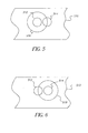
- Fig. 5 is a diagram useful in describing the problems of exposure and measurement flare; and
- Fig. 6 is a diagram useful in describing the problems of exposure and measurement flare.
-
- We have found that it is difficult to determine correction values for calibrating film data using measurements of a sequence of reference calibration patches exposed onto the roll of film, unless the arrangement of these patches is made in a specific manner to minimize artifacts during both exposure and measurement. Additionally, we have found that the sequence of reference calibration patches can be arranged to efficiently use space on the film. The arrangement of the reference calibration patches according to the present invention also enables greater robustness of the resulting reference calibration to data loss induced by the presence of extended linear defects, such as streaks, scratches, etc. The sequence of reference calibration patches used in this nvention could be a plurality of neutral patches, colored patches, or any combination thereof.
- When placing a sequence of reference calibration patches on a photographic element, problems may arise in an exposure step, in a measurement step, or in a design choice which will determine a preferred arrangement and exposure assignment. A photographic element includes at least a base with a photosensitive layer that is sensitive to light to produce a developable latent image. The photosensitive layer may contain conventional silver halide chemistry, or other photosensitive materials such as thermal or pressure developable chemistries. It can have a transparent base, a reflective base, or a base with a magnetically sensitive coating. The photographic element can be processed through standard chemical processes, including but not limited to Kodak Processes C-41 and its variants, ECN-2, VNF-1, ECP-2 and its variants, D-96, D-97, E-4, E-6, K-14, R-3, and RA-2SM, or RA-4; Fuji Processes CN-16 and its variants, CR-6, CP-43FA, CP-47L, CP-48S, RP-305, RA-4RT; Agfa MSC 100/101/200 Film and Paper Processes, Agfacolor Processes 70, 71, 72 and 94, Agfachrome Processes 44NP and 63; and Konica Processes CNK-4, CPK-2-22, DP, and CRK-2, and Konica ECOJET HQA-N, HQA-F, and HQA-P Processes. The photographic element can be processed using alternate processes such as apparently dry processes that may retain some or all of the developed silver or silver halide in the element or that may include lamination and an appropriate amount of water added to swell the photographic element. Depending upon the design of the photographic element, the photographic element can also be processed using dry processes that may include thermal or high pressure treatment. The processing may also include a combination of apparently dry, dry, and traditional wet processes. Examples of suitable alternate and dry processes include the processes disclosed in: US Serial Nos. 60/211,058 filed June 3, 2000 by Levy et al.; 60/211,446 filed June 3, 2000 by Irving et al.; 60/211,065 filed June 3, 2000 by Irving et al.; 60/211,079 filed June 3, 2000 by Irving et al.; EP Patent No. 0762201A1 published March 12, 1997, by Ishikawa et al.; EP Patent No. 0926550A1, published December 12, 1998, by Iwai, et al.; US Patent No. 5,832,328 issued November 3, 1998 to Ueda; US Patent No. 5,758,223 issued May 26, 1998 to Kobayashi, et al.; US Patent No. 5,698,382 issued December 16, 1997 to Nakahanada, et al.; US Patent No. 5,519,510 issued May 21, 1996 to Edgar: and US Patent No. 5,988,896 issued November 23, 1999 to Edgar.
- Referring to Fig. 5, in the exposure step, when two
reference calibration patches photographic element 510, light intended to exposepatch 512 can impinge upon alarger area 516 overlapping the area intended forpatch 514. Several mechanisms, including flare and light scattering, can cause the exposure to impinge on thelarger area 516. Conversely, referring to Fig. 6, light intended to exposepatch 514 can similarly impinge upon alarger area 518 overlapping the area intended forpatch 512. An example of various pairs of desired exposures designated forpatches columns 1 and 2 of Table 1 below. In this example, exposure ofpatch 512 results in flare throughout the surroundingarea 516 which is assumed to be at a level of 1% of the exposure intended forpatch 512. Thus, an incremental exposure is given topatch 514 wherearea 516 overlaps it. Similarly, exposure ofpatch 514 results in flare throughout the surroundingarea 518 which is assumed to be at a level of 1% of the exposure intended forpatch 514. Thus, an incremental exposure is also given topatch 512 wherearea 518 overlaps it. As a result of such exposure cross-contamination, portions of the patches would actually receive the exposure shown in columns 3 and 4 of Table 1. The resulting log exposure errors are shown in columns 5 and 6.Example Desired Exp. 512 Desired Exp. 514 Actual Exp. 512 Actual Exp. 514 Log Exp. error 512Log Exp. error 5141 1000 1 1000.01 11 4.3E-6 1.041 2 1000 10 1000.1 20 4.3E-5 0.301 3 1000 100 1001 110 4.3E-4 0.041 4 1000 500 1005 510 2.2E-3 0.009 5 2 1 2.01 1.02 2.2E-3 0.009 - These examples show that in all cases, the error in log exposure is smaller in
patch 512, designated to receive a higher level of exposure, than that inpatch 514, designated to receive a lower level of exposure. Further, the relative errors depend only on the ratio of the levels, as seen in the fourth and fifth row of the table. In addition, the closer the ratio of exposures is to one, the lower the log exposure errors become, as seen in the first four rows of the table wherein the absolute amount of contamination frompatch 512 remains constant at 10 units. - The response of a photographic element, such as a color negative film, is typically linear in log exposure over a wide range of exposures. In such a case, the effect of cross-contamination of reference calibration patches having different exposures in proximity to each other is clearly lessened if the exposure levels of nearby patches are nearby in exposure ratio or equivalent in log exposure.
- In typical applications, the intensity of stray light, due to such mechanisms as optical flare from an illumination system or in-film light scattering, falls off continuously with distance. For a given acceptable ratio of inadvertent to desired exposure, the closer two patches are in their desired illumination level, the more closely the patches may be placed before unacceptable exposure occurs at all and the smaller any zone within a patch of unacceptable contamination will be. Conversely, the closer two patches are in their desired illumination level at a given patch spacing, the lower the ratio of inadvertent to desired exposure at any point becomes. Reference calibration patches created in a system with significant stray light can be used so long as they are sufficiently large or widely enough separated to accommodate subsequent measurement in a portion that has an acceptable level of inadvertent exposure from other, typically only neighboring, patches. Thus assignments of exposures which tend to place patches with similar exposures near each other will result in more compact arrangements or larger useful zones for measurement.
- Referring again to Fig. 6, when
reference calibration patches photographic element 510 such as a negative working film, are measured using a device such as a film scanner, the dominant effect of the cross-contamination is reversed. In a typical scanner, a linear or area array of sensors is used to simultaneously view an illuminated narrow band or large area of the film, respectively. In the event that multiple patches or portions thereof are simultaneously illuminated and viewed by the sensor array, stray light from one patch can inadvertently affect the measured density in the sensors designated to view another patch. In this case, the dominant effect is from light transmitted through a lower density patch 514 (resulting from development of a patch receiving a lower exposure), causing inadvertent additional illumination of sensors intended to receive radiation in anarea 518, some of which are intended to be measuring a higher density patch 512 (resulting from development of a patch receiving a higher exposure). - For a given acceptable ratio of inadvertent to desired sensor illumination, again, this effect falls off with distance in typical applications, so proximity again should be correlated, this time with density level. For a given acceptable ratio of inadvertent to desired sensor illumination, the closer two adjacent patches are in their desired density level, the narrower the physical zone in which unacceptable sensor illumination occurs.
- For negative working photographic elements, it has been found that measurement error due to stray light is increased if the higher exposure (and hence density) reference calibration patches are separated from each other to such an extent that there is negligible exposure between the
flare regions 516 surrounding each patch. In such a case, the negligible density regions between patches can strongly affect measurements within a given patch. Hence it is desirable in negative working photographic materials that the reference calibration patches be located closely enough so that theflare regions 516 overlap. - If a patch is large enough so that the limited range of these sources of contamination does not affect data taken near the center of a patch and the central area is sufficiently large to provide adequate data for statistical treatments, accurate measurements may still be obtained. Thus, it is preferable that the patches be larger and closer together rather than smaller and more widely separated.
- A typical prior art step tablet arrangement, with a sequence of rectangular patches juxtaposed in a linear arrangement, accomplishes the goals of reducing the effects of exposure and measurement errors by placing exposures in a monotonically increasing sequence from the lowest exposure at one end to the highest exposure at the other. This arrangement is optimal from exposure and measurement standpoints in that the exposure and measurement effects are made as small as practicable for a given set of desired exposures and densities by minimizing the exposure ratios and density differences between the steps. When the extent of contamination effects in exposure and measurement is factored in, a portion of each step edge will be outside an acceptable range for measurement error. Additionally, the presence of measurement noise and random nonuniformity in density requires that a number of measurements be averaged. Elimination of unacceptable data and use of multiple data points for averaging implies a minimum size requirement for a step. The problem with the traditional step tablet arrangement is that given the minimum size for each step, the tablet becomes too long to conveniently fit on a conventional film strip. Reference calibration patch arrangements that are arranged in two dimensional arrays are more efficient in using the space on a film strip, but such arrays admit a possibility of having adjacent patches that are undesirably far apart in the exposure sequence. For example, if a long sequence of patches is desired but fewer patches can be fit into a desired length, the sequence of patches can be rearranged into a two dimensional array comprising a collection of linear subarrays, with each subarray comprising a segment of the sequence. This may be accomplished in a variety of ways. One way is to use a small number of longer segments. However, such an arrangement can place patches adjacent to each other that are widely separated in the sequence. This could lead to a need for a greater spacing between the linear subarrays than within a linear subarray to avoid exposure or measurement flare artifacts, which would in turn increase the area needed on the photographic element. Another way is to use a larger number of shorter segments. This reduces the number of steps between neighboring patches in the array and allows for a lesser spacing between the linear subarrays.
- Additionally, by offsetting the linear subarrays by half the center-to-center distance within each subarray, the subarrays can be placed such that the patches form a hexagonal close packed array, with equal center-to-center distance between all nearest neighbor patches. This achieves a closer packing than a rectangular array, and improves the overlap between the flare regions around each patch that is useful in reducing scanning flare effects.
- In film systems, the dominant direction of extended defects such as streaks and scratches tends to be along the length of a film strip. Such a defect could corrupt the data from multiple patches aligned with the length of the strip. Ability to detect, eliminate, and replace defective data in the generation of reference calibration tables can be enhanced by arranging patches so that a single linear defect cannot corrupt the data from a subset of patches that form a contiguous segment of the exposure sequence. Additionally, arrangements that reduce the number of patches aligned with the length of the strip would lead to less data loss from such a linear defect. The optimal solution from the standpoint of minimizing the effects of linear defects alone would be to have one patch in each row, that is, to have the patches aligned in a linear array across the film strip. However, in a film strip, the widthwise dimension is shorter than the lengthwise direction, so this solution is impractical.
- The use of arrangements having patches placed so that the offset linear subarrays are aligned perpendicular to the length of the strip, reduces the number of patches that would be affected by a single longitudinal defect relative to a parallel alignment or rectangular array. In a close-packed arrangement, if the area to be measured is less than 86.6% of the inter-spot spacing, any such defect would affect a patch in at most every other subarray of patches.
- Referring to Fig. 1, a
photographic element 10, for example, a strip of color negative film with aperforation 12 is exposed with a two-dimensional array ofreference calibration patches 14 representing a sequence of exposures. Thephotographic element 10 exhibits linear defects, such as film scratches, in a predominant direction indicated by arrow A. This array of reference calibration patches is advantageously placed in an area of the film strip relative to the perforation analogously to placement of an ordinary image frame, as disclosed in co-pending patent application US Serial No. 09/635,496. The arrangement of these reference calibration patches, including specific locations of the patches within the array and assignment of exposures to these locations is the subject of the present invention. - Referring to Fig. 2, an arrangement of 23 circular reference calibration patches is shown. Although circular patches are shown, other patch shapes, such as square, rectangular, and hexagonal can be employed. The patches are arranged on centers that form vertical columns with vertical offsets between each column to effect more efficient packing. The exposure sequence increases along diagonal paths starting with a first (or zero)
exposure patch 200, followed by the next steps in the exposure sequence in order in the next diagonal group ofpatches next patch 208 at the start of the next diagonal group, and proceeding in likewise fashion up to thehighest step 244 in the exposure sequence. As seen from Fig. 2, a singlelinear defect 210 parallel to arrow A in the top row of patches will affect the reference calibration patches corresponding to the first, fourth and ninth steps in the sequence. A linear defect 212 in the second row will affect reference calibration patches corresponding to the third and eighth steps. Thus, the exposures of reference calibration patches affected by a single linear defect are separated by more than one step in the exposure sequence. - Referring to Fig. 3, the same two dimensional arrangement of reference calibration patches may have a different assignment of steps in the exposure sequence to the patches that further separates the patches in the sequence affected by a linear defect at the expense of having adjacent patches separated by a greater number of steps in parts of the array. In this example, the steps progress along vertical columns starting with a
lowest exposure patch 300, followed by increasing exposures in thecolumn patch 301 at the start of the next vertical column, and proceeding in likewise fashion up to thehighest exposure patch 344. A singlelinear defect 310 parallel to arrow A in the top row of patches will affect the reference calibration patches corresponding to the first, tenth, and nineteenth steps of the sequence. Alinear defect 312 in the second row will affect the reference calibration patches corresponding to the sixth and fifteenth steps. Thus, the reference calibration patches affected by a single linear defect are more widely separated in the exposure sequence in this arrangement, however, some of the differences in steps in the exposure sequence of adjacent patches are also increased. Forexample neighboring patches patches - Referring to Fig. 4, an alternative arrangement of patches is illustrated which comprises the same number of patches as shown in Fig. 2 and Fig. 3 but arranged in a rectangular array with nine columns of patches. The exposures of the patches increase along vertical columns starting with a
lowest exposure patch 400, followed by increasing exposures inpatches patches highest exposure patch 444. - All of the arrangements shown in Figs. 2, 3 and 4 share the features that the patches form a two dimensional array such that nearest neighbors in the predominant direction are not nearest neighbors in the exposure sequence, whereby the effects of a linear defect are reduced; and the maximum number of steps in the exposure sequence between a reference calibration patch and that of its nearest neighbors in any direction is less than a predetermined number, whereby the effects of flare are reduced. In the examples shown in Figs. 2 and 3, the maximum number of steps in the exposure sequence is five. In Fig. 4 the maximum number of steps in the exposure sequence is three.
- In summary, sensitivity to stray light in exposure and measurement is reduced by placing similar patches closer and dissimilar spots more distant from each other. Sensitivity to extended linear defects is reduced by minimizing the number of measured spots that would be intersected by such a defect and by arranging exposures in each row so that the affected exposures are more widely separated. Constraints on the overall dimensions of an arrangement as well as tradeoffs between robustness to stray light and robustness to extended linear defects can lead to different arrangements that are consistent with these design principles.
Claims (10)
- A photographic element, the photographic element exhibiting linear defects in a predominant direction, comprising:a) a base;b) a photosensitive layer on the base; andc) a latent image of a plurality of reference calibration patches produced by a sequence of exposures on the photosensitive layer, the reference calibration patches being arranged in a two dimensional array wherein nearest neighbors in the predominant direction are not nearest neighbors in the exposure sequence and the maximum number of steps in the exposure sequence between a reference calibration patch and that of its nearest neighbors in any direction is less than a predetermined number.
- The photographic element claimed in claim 8, wherein the minimum number of steps in the exposure sequence between a reference calibration patch and its nearest neighbors in the predominant direction is maximized.
- The photographic element claimed in claim 8, wherein the maximum number of steps in the exposure sequence between a reference calibration patch and its nearest neighbors is minimized.
- The photographic element claimed in claim 8, wherein the predetermined number varies with step number.
- The photographic element claimed in claim 8, wherein the reference calibration patches are circular and the array is a close packed hexagonal array.
- The photographic element claimed in claim 8, wherein the photographic element is a film strip and the predominant direction is the length of the film strip.
- The photographic element claimed in claim 8, wherein the photographic element is a photographic paper web and the predominant direction is the length of the web.
- The photographic element claimed in claim 8, wherein the photosensitive layer contains conventional silver halide chemistry.
- The photographic element claimed in claim 8, wherein the photosensitive layer contains thermal developable chemistry.
- The photographic element claimed in claim 8, wherein the photosensitive layer contains pressure developable chemistry.
Applications Claiming Priority (2)
| Application Number | Priority Date | Filing Date | Title |
|---|---|---|---|
| US09/635,257 US6284445B1 (en) | 2000-08-09 | 2000-08-09 | Reference calibration patch arrangement to minimize exposure and measurement artifacts and maximize robustness to defects |
| US635257 | 2000-08-09 |
Publications (1)
| Publication Number | Publication Date |
|---|---|
| EP1180720A1 true EP1180720A1 (en) | 2002-02-20 |
Family
ID=24547069
Family Applications (1)
| Application Number | Title | Priority Date | Filing Date |
|---|---|---|---|
| EP01202868A Withdrawn EP1180720A1 (en) | 2000-08-09 | 2001-07-27 | Calibration patches |
Country Status (4)
| Country | Link |
|---|---|
| US (1) | US6284445B1 (en) |
| EP (1) | EP1180720A1 (en) |
| JP (1) | JP2002107845A (en) |
| CN (1) | CN1337596A (en) |
Families Citing this family (10)
| Publication number | Priority date | Publication date | Assignee | Title |
|---|---|---|---|---|
| US6442497B1 (en) * | 2000-04-14 | 2002-08-27 | Eastman Kodak Company | Calibration method and strip for film scanners in digital photofinishing systems |
| US7113627B1 (en) | 2000-08-09 | 2006-09-26 | Eastman Kodak Company | Location of extended linear defects |
| US7286261B2 (en) * | 2001-10-02 | 2007-10-23 | Hewlett-Packard Development Company, L.P. | Color calibration color value correction |
| FR2837007B1 (en) * | 2002-03-07 | 2004-06-11 | Eastman Kodak Co | METHOD FOR OBTAINING A SENSITOMETRIC INDICATOR WITH A GRADIENT OF EXPOSURE AND A PHOTOGRAPHIC ELEMENT COMPRISING SUCH A INDICATOR |
| FR2837006B1 (en) | 2002-03-07 | 2004-11-05 | Eastman Kodak Co | EXPOSURE SYSTEM FOR OBTAINING A GRADIENT SENSITOMETRIC INDICATOR |
| FR2846414B1 (en) * | 2002-10-24 | 2005-01-07 | Eastman Kodak Co | METHOD FOR ESTABLISHING A SENSITOMETRIC CURVE OF A PHOTOGRAPHIC MEDIUM |
| US7207645B2 (en) * | 2003-10-31 | 2007-04-24 | Busch Brian D | Printer color correction |
| EP2134099B1 (en) | 2008-06-13 | 2015-10-14 | Thomson Licensing | Method of compensation for spatial non-uniformities of image devices |
| EP2134073A1 (en) | 2008-06-13 | 2009-12-16 | THOMSON Licensing | Rectangular calibration chart for calibration of color device |
| CN109363769B (en) * | 2018-11-13 | 2024-02-23 | 李成利 | Magnetic resonance positioning device and positioning method |
Citations (3)
| Publication number | Priority date | Publication date | Assignee | Title |
|---|---|---|---|---|
| US4977521A (en) * | 1988-07-25 | 1990-12-11 | Eastman Kodak Company | Film noise reduction by application of bayes theorem to positive/negative film |
| EP0751420A1 (en) * | 1995-06-26 | 1997-01-02 | Eastman Kodak Company | Automated photofinishing apparatus |
| EP0770905A2 (en) * | 1995-10-25 | 1997-05-02 | Eastman Kodak Company | Digital process sensitivity correction |
Family Cites Families (28)
| Publication number | Priority date | Publication date | Assignee | Title |
|---|---|---|---|---|
| US3718074A (en) | 1971-05-13 | 1973-02-27 | R Davis | Color data acquisition camera |
| US4211558A (en) | 1975-07-23 | 1980-07-08 | Konishiroku Photo Industry Co., Ltd. | Color printing method |
| DE2803380A1 (en) | 1978-01-26 | 1979-08-02 | Agfa Gevaert Ag | DEVICE FOR APPLYING TEST EXPOSURE |
| DE2911566C2 (en) | 1979-03-23 | 1987-03-12 | Agfa-Gevaert Ag, 5090 Leverkusen | Method and device for calibrating a colour copying machine |
| US4365882A (en) | 1981-06-29 | 1982-12-28 | Disbrow Lynnford E | Color standard method and apparatus |
| JPS5983144A (en) | 1982-11-02 | 1984-05-14 | Fuji Photo Film Co Ltd | Method for correcting photometric condition of photographic film |
| US4786792A (en) | 1983-10-12 | 1988-11-22 | Drexler Technology Corporation | Transmissively read quad density optical data system |
| US4634850A (en) | 1983-10-12 | 1987-01-06 | Drexler Technology Corporation | Quad density optical data system |
| US4884102A (en) | 1985-05-22 | 1989-11-28 | Fuji Photo Film Co., Ltd. | Controlling method for a photographic system |
| US4881095A (en) | 1987-09-11 | 1989-11-14 | Fuji Photo Film Co., Ltd. | Process for developing photographed film and for printing images through developed film |
| US4874936A (en) | 1988-04-08 | 1989-10-17 | United Parcel Service Of America, Inc. | Hexagonal, information encoding article, process and system |
| US4939354A (en) | 1988-05-05 | 1990-07-03 | Datacode International, Inc. | Dynamically variable machine readable binary code and method for reading and producing thereof |
| US5267030A (en) | 1989-12-22 | 1993-11-30 | Eastman Kodak Company | Method and associated apparatus for forming image data metrics which achieve media compatibility for subsequent imaging application |
| EP0452157B1 (en) | 1990-04-13 | 1995-10-18 | Canon Kabushiki Kaisha | Image recording apparatus |
| JP3040433B2 (en) | 1990-06-11 | 2000-05-15 | キヤノン株式会社 | Correction data creation method |
| US5075716A (en) | 1990-11-29 | 1991-12-24 | Eastman Kodak Company | Apparatus and method for precisely exposing radiation sensitive materials |
| US5198907A (en) | 1991-08-23 | 1993-03-30 | Eastman Kodak Company | Method and appratus for automatically locating predefined exposure areas in a scanned image |
| CA2093449C (en) | 1992-07-17 | 1997-06-17 | Albert D. Edgar | Electronic film development |
| US5591956A (en) | 1995-05-15 | 1997-01-07 | Welch Allyn, Inc. | Two dimensional data encoding structure and symbology for use with optical readers |
| US5452055A (en) | 1994-07-14 | 1995-09-19 | Eastman Kodak Company | Apparatus and method for making a reference exposure on a leading and/or trailing portion of a filmstrip |
| US5767983A (en) | 1995-03-24 | 1998-06-16 | Fuji Photo Film Co., Ltd. | Color copying apparatus for determining exposure amount from image data of an original image and a reference image |
| US5832328A (en) | 1995-05-19 | 1998-11-03 | Konica Corporation | Automatic processing machine for a silver halide photograhic light-sensitive material |
| US5756269A (en) | 1995-08-22 | 1998-05-26 | Fuji Photo Film Co., Ltd. | Method of forming images |
| US5758223A (en) | 1995-09-04 | 1998-05-26 | Konica Corporation | Automatic processing machine for silver halide photographic light-sensitive material |
| US5698382A (en) | 1995-09-25 | 1997-12-16 | Konica Corporation | Processing method for silver halide color photographic light-sensitive material |
| US5988896A (en) | 1996-10-26 | 1999-11-23 | Applied Science Fiction, Inc. | Method and apparatus for electronic film development |
| JPH11316448A (en) | 1997-12-22 | 1999-11-16 | Konica Corp | Image information forming method, photographic photosensitive material, film unit with lens, image display method and image output method |
| JP3767218B2 (en) | 1997-12-25 | 2006-04-19 | コニカミノルタホールディングス株式会社 | Image information recording method |
-
2000
- 2000-08-09 US US09/635,257 patent/US6284445B1/en not_active Expired - Fee Related
-
2001
- 2001-07-27 EP EP01202868A patent/EP1180720A1/en not_active Withdrawn
- 2001-08-06 JP JP2001238416A patent/JP2002107845A/en active Pending
- 2001-08-09 CN CN01125204A patent/CN1337596A/en active Pending
Patent Citations (3)
| Publication number | Priority date | Publication date | Assignee | Title |
|---|---|---|---|---|
| US4977521A (en) * | 1988-07-25 | 1990-12-11 | Eastman Kodak Company | Film noise reduction by application of bayes theorem to positive/negative film |
| EP0751420A1 (en) * | 1995-06-26 | 1997-01-02 | Eastman Kodak Company | Automated photofinishing apparatus |
| EP0770905A2 (en) * | 1995-10-25 | 1997-05-02 | Eastman Kodak Company | Digital process sensitivity correction |
Also Published As
| Publication number | Publication date |
|---|---|
| US6284445B1 (en) | 2001-09-04 |
| CN1337596A (en) | 2002-02-27 |
| JP2002107845A (en) | 2002-04-10 |
Similar Documents
| Publication | Publication Date | Title |
|---|---|---|
| EP1232418B1 (en) | Method and system for using calibration patches in electronic film processing | |
| US6284445B1 (en) | Reference calibration patch arrangement to minimize exposure and measurement artifacts and maximize robustness to defects | |
| US6866199B1 (en) | Method of locating a calibration patch in a reference calibration target | |
| JP5585228B2 (en) | Image inspection apparatus, image inspection method, and image forming apparatus | |
| EP1184720A2 (en) | Method and photographic element for calibrating digital images | |
| JPH09120445A (en) | Method and apparatus for correction of output signals of plurality of photodetection elements | |
| US6813392B2 (en) | Method and apparatus for aligning multiple scans of the same area of a medium using mathematical correlation | |
| EP0509170A1 (en) | 3-D camera, preloaded and integrated high-speed printing system | |
| US6280914B1 (en) | Photographic element with reference calibration data | |
| JP3591922B2 (en) | Light intensity measurement device | |
| US6475711B1 (en) | Photographic element and digital film processing method using same | |
| US7113627B1 (en) | Location of extended linear defects | |
| JP2000152046A (en) | Filed lens for digital camera | |
| US4642462A (en) | Method of correcting radiation image read-out error | |
| JP2541330B2 (en) | Light receiving unit of image reading device | |
| JPH11202419A (en) | Image recording device | |
| JP2014053106A (en) | Illumination device and image inspection device | |
| JPH08179446A (en) | Formation of photographic print | |
| JP3829709B2 (en) | Scanner device | |
| JP2001016400A (en) | Line sensor and image processing unit using the same | |
| JPH0256541A (en) | Image forming device | |
| JPH0410582B2 (en) | ||
| JPH01151262A (en) | Image sensor for measurement use | |
| US20020085842A1 (en) | Apparatus and method for recording on a black & white film information comprising a pattern of coloured light and apparatus and method for reconstructing from a black & white image such information | |
| JPH03211962A (en) | Digital image reading device |
Legal Events
| Date | Code | Title | Description |
|---|---|---|---|
| PUAI | Public reference made under article 153(3) epc to a published international application that has entered the european phase |
Free format text: ORIGINAL CODE: 0009012 |
|
| AK | Designated contracting states |
Kind code of ref document: A1 Designated state(s): DE GB Kind code of ref document: A1 Designated state(s): AT BE CH CY DE DK ES FI FR GB GR IE IT LI LU MC NL PT SE TR |
|
| AX | Request for extension of the european patent |
Free format text: AL;LT;LV;MK;RO;SI |
|
| 17P | Request for examination filed |
Effective date: 20020617 |
|
| AKX | Designation fees paid |
Free format text: DE GB |
|
| STAA | Information on the status of an ep patent application or granted ep patent |
Free format text: STATUS: THE APPLICATION IS DEEMED TO BE WITHDRAWN |
|
| 18D | Application deemed to be withdrawn |
Effective date: 20060817 |