EP1180662A2 - Position transducer - Google Patents
Position transducer Download PDFInfo
- Publication number
- EP1180662A2 EP1180662A2 EP01107190A EP01107190A EP1180662A2 EP 1180662 A2 EP1180662 A2 EP 1180662A2 EP 01107190 A EP01107190 A EP 01107190A EP 01107190 A EP01107190 A EP 01107190A EP 1180662 A2 EP1180662 A2 EP 1180662A2
- Authority
- EP
- European Patent Office
- Prior art keywords
- carriage
- bearing
- slider
- scale
- position transducer
- Prior art date
- Legal status (The legal status is an assumption and is not a legal conclusion. Google has not performed a legal analysis and makes no representation as to the accuracy of the status listed.)
- Granted
Links
- 238000001514 detection method Methods 0.000 claims description 17
- 241000668842 Lepidosaphes gloverii Species 0.000 claims description 5
- 238000005096 rolling process Methods 0.000 abstract description 6
- 230000008878 coupling Effects 0.000 description 50
- 238000010168 coupling process Methods 0.000 description 50
- 238000005859 coupling reaction Methods 0.000 description 50
- 238000005259 measurement Methods 0.000 description 10
- 230000003746 surface roughness Effects 0.000 description 6
- 239000000463 material Substances 0.000 description 4
- 230000008961 swelling Effects 0.000 description 3
- 230000015556 catabolic process Effects 0.000 description 2
- 239000000919 ceramic Substances 0.000 description 2
- 238000006731 degradation reaction Methods 0.000 description 2
- 238000006073 displacement reaction Methods 0.000 description 2
- 230000014759 maintenance of location Effects 0.000 description 2
- 230000000717 retained effect Effects 0.000 description 2
- 239000000243 solution Substances 0.000 description 2
- RAQQRQCODVNJCK-JLHYYAGUSA-N N-[(4-amino-2-methylpyrimidin-5-yl)methyl]-N-[(E)-5-hydroxy-3-(2-hydroxyethyldisulfanyl)pent-2-en-2-yl]formamide Chemical group C\C(N(Cc1cnc(C)nc1N)C=O)=C(\CCO)SSCCO RAQQRQCODVNJCK-JLHYYAGUSA-N 0.000 description 1
- 229910000831 Steel Inorganic materials 0.000 description 1
- 229910052782 aluminium Inorganic materials 0.000 description 1
- XAGFODPZIPBFFR-UHFFFAOYSA-N aluminium Chemical compound [Al] XAGFODPZIPBFFR-UHFFFAOYSA-N 0.000 description 1
- 238000005452 bending Methods 0.000 description 1
- 238000010276 construction Methods 0.000 description 1
- 239000000428 dust Substances 0.000 description 1
- 239000011521 glass Substances 0.000 description 1
- 238000001746 injection moulding Methods 0.000 description 1
- 238000009434 installation Methods 0.000 description 1
- 238000003754 machining Methods 0.000 description 1
- 229910052751 metal Inorganic materials 0.000 description 1
- 239000002184 metal Substances 0.000 description 1
- 239000007769 metal material Substances 0.000 description 1
- 230000003287 optical effect Effects 0.000 description 1
- 239000012791 sliding layer Substances 0.000 description 1
- 239000010959 steel Substances 0.000 description 1
Images


Classifications
-
- G—PHYSICS
- G01—MEASURING; TESTING
- G01D—MEASURING NOT SPECIALLY ADAPTED FOR A SPECIFIC VARIABLE; ARRANGEMENTS FOR MEASURING TWO OR MORE VARIABLES NOT COVERED IN A SINGLE OTHER SUBCLASS; TARIFF METERING APPARATUS; MEASURING OR TESTING NOT OTHERWISE PROVIDED FOR
- G01D5/00—Mechanical means for transferring the output of a sensing member; Means for converting the output of a sensing member to another variable where the form or nature of the sensing member does not constrain the means for converting; Transducers not specially adapted for a specific variable
- G01D5/26—Mechanical means for transferring the output of a sensing member; Means for converting the output of a sensing member to another variable where the form or nature of the sensing member does not constrain the means for converting; Transducers not specially adapted for a specific variable characterised by optical transfer means, i.e. using infrared, visible, or ultraviolet light
- G01D5/32—Mechanical means for transferring the output of a sensing member; Means for converting the output of a sensing member to another variable where the form or nature of the sensing member does not constrain the means for converting; Transducers not specially adapted for a specific variable characterised by optical transfer means, i.e. using infrared, visible, or ultraviolet light with attenuation or whole or partial obturation of beams of light
- G01D5/34—Mechanical means for transferring the output of a sensing member; Means for converting the output of a sensing member to another variable where the form or nature of the sensing member does not constrain the means for converting; Transducers not specially adapted for a specific variable characterised by optical transfer means, i.e. using infrared, visible, or ultraviolet light with attenuation or whole or partial obturation of beams of light the beams of light being detected by photocells
- G01D5/347—Mechanical means for transferring the output of a sensing member; Means for converting the output of a sensing member to another variable where the form or nature of the sensing member does not constrain the means for converting; Transducers not specially adapted for a specific variable characterised by optical transfer means, i.e. using infrared, visible, or ultraviolet light with attenuation or whole or partial obturation of beams of light the beams of light being detected by photocells using displacement encoding scales
- G01D5/34746—Linear encoders
- G01D5/34753—Carriages; Driving or coupling means
Definitions
- the present invention relates to a position transducer for use as installed to the body of a machine tool, industrial equipment, precision measurement equipment or the like, each provided with a moving or movable part and a stationary part, which move linearly in relation to each other, to measure an amount of travel and moved position of the moving part relative to the stationary part.
- the position transducer is installed to a moving part and a stationary part of a machine tool, industrial equipment, precision measuring equipment or the like (will be referred to simply as “machine body” hereunder), which move linearly in relation to each other, to measure an amount of travel and moved position of the moving part relative to the stationary part, for example.
- the conventional position transducer includes a long graduated scale provided to detect a position during relative movement of the stationary and moving parts, and a sensor unit having disposed therein a detection head which reads a graduation provided on the scale.
- the scale is fixed to the stationary part while the sensor unit is fixed to the moving part.
- the sensor unit includes a slider disposed on the scale to read a displacement on the graduation by the detection head, and a carrier coupled to the slider to move along with the moving part of the machine body, the slider being coupled to the carrier by a coupling.
- the slider As the carrier is moved along with a linear movement of the moving part of the machine body, the slider is toed or pushed by the coupling connecting the slider and carrier, by the coupler, to the carrier and travels on and longitudinally of the scale.
- the position transducer reads, by the detection head disposed on the slider, a displacement of the slider on the graduation on the scale to measure an amount of travel and moved position of the moving part relative to the stationary part.
- the carrier moves following up a meandering or swelling movement of the moving part of the machine body.
- the slider is disposed in contact with the scale and moves following up a surface condition of the scale, more specifically, a meandering or swelling of the scale surface. That is, in the position transducer, a relatively moved position and relative moving distance are measured by the slider and carrier destined for different movements, respectively, and so the positions of the slider and carrier are possibly deviated from each other in the course of a measurement.
- the slider and carrier are coupled to each other by applying a force to the slider or carrier independently of a contact point at the coupling connecting the slider and carrier.
- the above positional deviation cause a dynamic vector in a direction other than the moving direction of the slider, in other words, in a direction in which the linear movement of the slider is inhibited, which results in a measurement error due to a return error or degradation of repeatability precision.
- a contact friction due to the dynamic vector developed at the coupling connecting the slider and carrier will inhibit the slider from movinglinearly, which will influence the repeatability precision and return error.
- a position transducer is known from the disclosure in the Japanese Published Unexamined Application No. 4-231810, in which a scanning unit which scans a scale plate is mounted with a coupling fixed in a measuring direction on a mount base of a machine tool, the coupling consisting of a first plate-shaped coupling piece fixed to the scanning unit and a second pin-shaped coupling piece fixed to a carriage and having a spheric end face, and a sliding layer is provided between the coupling pieces.
- a scanning unit which scans a scale plate is mounted with a coupling fixed in a measuring direction on a mount base of a machine tool, the coupling consisting of a first plate-shaped coupling piece fixed to the scanning unit and a second pin-shaped coupling piece fixed to a carriage and having a spheric end face, and a sliding layer is provided between the coupling pieces.
- a position transducer is known from the disclosure in the Japanese Published Unexamined Application No. 5-87552, in which an intermediate coupling member is slidably coupled to a slider-side coupling member and the intermediate coupling and a carrier-side coupling member are put in line contact with each other in a concavo-convex relation to correct a detecting precision error.
- the intermediate coupling member and carrier-side coupling member are put in line contact with each other in the concavo-convex relation to form a universal coupling mechanism.
- the slider-side coupling member and intermediate coupling member are moved with a friction between them while being in surface contact because of the straightness of the machine vibration and travel and that of the scale.
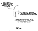
- a slider and carriage will be deviated from each other for the amplitude of a deflection caused by a machine motion and a swelling surface of the scale and the deflection will appear as a cosine error.
- a position transducer including a long scale having a position detecting graduation provided thereon along the length thereof, a carriage moving along the scale and having a detection head which reads the graduation to provide a position detection signal, and a slider coupled to the carriage and moving the carriage along the length of the scale, in which when the slider and carriage are moved relative to each other, measurement error is reduced by eliminating Abbe error caused by a positional change taking place between coupling pieces.
- a position transducer including a long scale having a position detecting graduation provided thereon along the length thereof, a carriage moving along the scale and having a detection head which reads the graduation to provide a position detection signal, and a slider coupled to the carriage and moving the carriage along the length of the scale; the carriage and slider are coupled to each other by an elastic member having an elasticity in a direction the carriage and slider are attracted towards each other, with the carriage and slider being butted to each other with a ball placed at one end of the carriage in the moving direction and between them.
- the carriage and slider is coupled to each other by the elastic member having the elasticity in the direction in which the carriage and slider are attracted towards each other, whereby when the slider and carriage move relative to each other, it is possible to eliminate Abbe error due to a positional change occurring between the coupling pieces and thus assure a high accuracy measurement with a reduced measurement error.
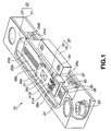
- FIGS. 1 to 4 there is illustrated the construction of an embodiment of the position transducer according to the present invention.
- the position transducer is generally indicated with a reference 10. As shown, the position transducer 10 includes a base unit 20, and a slider unit 30 provided slidably in relation to the base unit 20.
- the base unit 20 includes a long housing 21 as a base proper and a long scale 22 provided inside the hosing 21.
- the base unit 20 is to be fixed with fixing screws 23 in fixing holes formed therein to one of a moving part and stationary part of an object to be measured.
- the slider unit 30 includes a carriage 32 having provided thereon a detection head 31 to read a graduation on the scale 22, and a slider 33 which supports the carriage 32.
- the slider unit 30 is to be fixed with fixing screws 34 in fixing holes formed therein to the other of the moving part and stationary part of the object to be measured.
- the position transducer 10 is intended to measure a moved position and moving distance of the moving part and stationary part formed as part of an industrial machine, machine tool or the like and which move linearly relatively to each other.
- the base unit 20 is installed to the stationary part of the machine tool, for example, moving relative to the moving part, while the slider 33 coupled to the carriage 32 of the slider unit 30 is installed to the moving part of the machine tool.
- the long housing 21 as the base proper of the base unit 20 is a long member having a generally C-shaped section. It has encased therein the plate-like, long scale 22 and a round bar-shaped guide bar 24 so as to be longitudinally aligned therewith.
- One open side of the housing 21 is openably closed with two dust seals 25A and 25B each formed from a flexible material such as rubber, as shown in FIG. 1.
- the position transducer 10 since the housing is formed to have the generally C-shaped section the scale 22 is disposed to have a graduation recording surface thereof directed generally perpendicularly to the open side of the housing 21, foreign matter having entered the housing 21, if any, will not be able to stay on the scale surface having the graduation of the scale 22 recorded thereon, the position transducer 1 can always be kept for accurate detection of a position. Also, since the scale 22 incurs only a reduced deflection due to its own weight, it is possible to detect a position more stably with a high accuracy.
- the housing 21 may be a one formed by bending a metal plate having a predetermined rigidity or a one formed by injection molding of aluminum. Of course, the housing 21 may be formed by machining.
- the scale 22 is fixed at a predetermined position inside the housing 21 with both ends thereof being supported by a pair of brackets 26 disposed at longitudinal opposite ends of the housing 21.
- the scale 22 has a position detecting graduation 22b provided on one of main sides (will be referred to as "scale surface” hereunder) 22a thereof.
- the graduation 22b is a position signal recorded in succession at predetermined intervals along the length of the scale 22. It may be for example a series of pits or marks formed at predetermined intervals, a grating formed on the scale surface 22a, a series of polarized magnetic signals which will not look as a visible graduation but whose polarities are alternately opposite to each other, or the like.
- the scale 22 is formed from a material different from one to another depending upon the type of the detection head 31 which reads the graduation 22b to detect a position signal, for example, a vitreous material such as glass for an optical head used as the detection head or a metallic material for a magnetic head used as the detection head.
- a glass-made scale is used as the scale 22.
- the carriage 32 forming the slider unit 30 includes bearings 35a, 35b and 35c rolling on the scale surface 22a of the scale 22 provided inside the housing 21, and bearings 36a and 36b rolling along the guide bar 24, and thus the carriage 32 can freely be slid longitudinally on the scale surface 22a of the scale 22.
- the carriage 32 has provided in the central portion thereof at one end in the moving direction a plane bearing 37 having a bearing plane perpendicular to the moving direction.
- the slider 33 forming the slider unit 30 has a coupling arm 38 provided in the center of the upper surface thereof.
- the coupling arm 38 is inserted in the housing 21 from one open side of the latter.
- the coupling arm 38 of the slider 33 has a conical bearing 39 provided in a position opposite to the plane bearing 37 provided at the carriage 32.
- the conical bearing 39 has a bearing conical surface 39A having a vertex 39a in the moving direction of the carriage 32.
- the carriage 32 and coupling arm 38 are coupled to each other by two tension coil springs 41A and 41B.
- the two tension coil springs 41A and 41B are disposed symmetrically with respect to a straight line passing through the vertex 39a of the conical bearing surface 39A of the conical bearing 39 to provide an elasticity with which the ball 40 is kept retained between the plane bearing 37 and conical bearing 39.
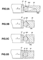
- FIGS. 5A to 5D there are schematically illustrated the relation between the ball 40 and conical bearing 39 forming together the coupling for the slider 33 and carriage 32 of the position transducer 10 in FIG. 1 and the angle of the bearing conical surface 39A of the conical bearing 39
- FIG. 6 shows the frictional force between the ball 40 and conical bearing 39. It is assumed that when the bearing conical surface 39A is parallel to the moving direction of the scale 22, the angle ⁇ is 0 deg. as shown in FIG. 6.
- FIGS. 5A to 5D show the relations between the ball 40 and conical bearing 39 when the angle ⁇ is 15 deg. (the vertical angle of the bearing conical surface 39A is 30 deg.), the angle ⁇ is 22.5 deg.
- the angle ⁇ is 45 deg. (the vertical angle of the bearing conical surface 39A is 90 deg.) and the angle ⁇ is 60 deg. (the vertical angle of the bearing conical surface 39A is 120 deg.) and the angle ⁇ is 90 deg. (the vertical angle of the bearing conical surface 39A is 180 deg.), respectively.
- the friction force f is 1.45N. Therefore, the vector components have to be designed for such a stress that even if the force with which the carriage 32 fastens the scale 22 exceeds 1.45N when the scale surface 22a meanders or swells or is mechanically vibrated.
- the ball 40 has a surface roughness of 0.05 ⁇ m or less and a hardness of Hrc 65 or less while the bearing conical surface 39A of the conical bearing 39 has a surface roughness of 0.4 ⁇ m or less and a hardness of Hrc 60 to 64.
- the plane bearing 37 has a flatness of 4 ⁇ m, surface roughness of 0.1 ⁇ m or less, and a hardness of Hrc 65 or more.
- the ball 40 is a ceramic ball or a steel ball. Also the conical bearing 39 and plane bearing 37 are made of ceramic or cemented material.
- the ball 40 and conical bearing 39 By forming the ball 40 and conical bearing 39 to have a surface roughness somewhat different from one to the other against fitting to each other, their surfaces can be well slidable on each other with no adhesion to each other even when a slow vibration takes place.
- the plane bearing 37 may be formed circular or quadrangular as shown in FIGS. 7A or 7B.
- the two tension coil springs 41A and 41B are provided in the positions symmetrical with respect to the straight line passing through the vertex 39a of the bearing conical surface 39A of the conical bearing 39 and parallel to the moving direction of the carriage 32.
- the structure of the slider unit 30 may be modified such that a single tension coil spring 41 is disposed on a straight line passing through the vertex 39a of the bearing conical surface 39A of the conical bearing 39 and parallel to the moving direction of the carriage 32, thereby providing an elasticity with which the ball 40 is kept retained between the plane bearing 37 and conical bearing 39.
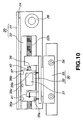
- a pivot bearing structure formed from a plurality of small-diameter balls 42 may be disposed on the bearing conical surface 39A of the conical bearing 39 as shown in FIG. 11.
- the conical bearing 39 may be replaced with a plane bearing 44 having a cylinder 43 as shown in FIGS. 5D and 12 and thus the ball may be supported between the pair of plane bearings 37 and 44 having a bearing plane perpendicular to the moving direction of the carriage 32.
Landscapes
- Physics & Mathematics (AREA)
- General Physics & Mathematics (AREA)
- Length Measuring Devices With Unspecified Measuring Means (AREA)
- Character Spaces And Line Spaces In Printers (AREA)
Abstract
Description
Claims (4)
- A position transducer comprising:a long scale having a position detecting graduation provided thereon along the length thereof;a carriage moving along the scale and having a detection head which reads the graduation to provide a position detection signal; anda slider coupled to the carriage and moving the carriage along the length of the scale;the carriage and slider are coupled to each other by an elastic member having an elasticity in a direction the carriage and slider are attracted towards each other, with the carriage and slider being butted to each other with a ball placed at one end of the carriage in the moving direction and between them.
- The position transducer as set forth in Claim 1, wherein the ball is supported by a plane bearing having a bearing plane perpendicular to the moving direction of the carriage and a conical bearing having a bearing conical surface which has a vertex in the moving direction of the carriage.
- The position transducer as set forth in Claim 1, wherein the ball is supported by a pair of plane bearings each having a bearing plane perpendicular to the moving direction of the carriage.
- The position transducer as set forth in Claim 1, wherein the ball is supported by a plane bearing having a bearing plane perpendicular to the moving direction of the carriage and a pivot bearing having a plurality of small-diameter balls.
Applications Claiming Priority (2)
| Application Number | Priority Date | Filing Date | Title |
|---|---|---|---|
| JP2000246419A JP4434452B2 (en) | 2000-08-15 | 2000-08-15 | Measuring device |
| JP2000246419 | 2000-08-15 |
Publications (3)
| Publication Number | Publication Date |
|---|---|
| EP1180662A2 true EP1180662A2 (en) | 2002-02-20 |
| EP1180662A3 EP1180662A3 (en) | 2003-03-26 |
| EP1180662B1 EP1180662B1 (en) | 2013-05-22 |
Family
ID=18736734
Family Applications (1)
| Application Number | Title | Priority Date | Filing Date |
|---|---|---|---|
| EP01107190.9A Expired - Lifetime EP1180662B1 (en) | 2000-08-15 | 2001-03-22 | Position transducer |
Country Status (4)
| Country | Link |
|---|---|
| US (1) | US6578283B2 (en) |
| EP (1) | EP1180662B1 (en) |
| JP (1) | JP4434452B2 (en) |
| ES (1) | ES2423210T3 (en) |
Cited By (3)
| Publication number | Priority date | Publication date | Assignee | Title |
|---|---|---|---|---|
| WO2005116783A1 (en) * | 2004-05-27 | 2005-12-08 | K.U.Leuven Research And Development | A measurement configuration based on linear scales able to measure to a target also moving perpendicular to the measurement axis |
| EP2037230A1 (en) * | 2007-09-15 | 2009-03-18 | Dr. Johannes Heidenhain GmbH | Length measuring device |
| CN109297395A (en) * | 2018-08-31 | 2019-02-01 | 贵州新安航空机械有限责任公司 | Test fixture of the test product close to characteristic energy |
Families Citing this family (22)
| Publication number | Priority date | Publication date | Assignee | Title |
|---|---|---|---|---|
| DE10041692A1 (en) * | 2000-08-24 | 2002-03-07 | Heidenhain Gmbh Dr Johannes | Length or angle measuring device |
| DE10204611B4 (en) * | 2002-02-05 | 2007-04-05 | Dr. Johannes Heidenhain Gmbh | Method and apparatus for attaching a scale or scale carrier |
| US7029565B2 (en) * | 2002-05-24 | 2006-04-18 | Konica Corporation | Method of producing optical element forming die |
| DE10225243B4 (en) * | 2002-06-07 | 2013-01-31 | Dr. Johannes Heidenhain Gmbh | Position measuring device and method for correcting thermal expansions, in particular for a processing machine |
| JP4223823B2 (en) * | 2003-02-10 | 2009-02-12 | ソニーマニュファクチュアリングシステムズ株式会社 | Scale equipment |
| US6989669B2 (en) * | 2003-05-06 | 2006-01-24 | Sri International | Systems and methods of recording piston rod position information in a magnetic layer on a piston rod |
| US6829838B1 (en) * | 2003-09-09 | 2004-12-14 | Hexagon Metrology Ab | Temperature compensation system for a coordinate measuring machine |
| DE102004043055B4 (en) * | 2004-09-06 | 2009-04-02 | Siemens Ag | Guide device for guiding a movable machine element of a machine |
| US7259553B2 (en) | 2005-04-13 | 2007-08-21 | Sri International | System and method of magnetically sensing position of a moving component |
| US7191541B1 (en) | 2005-12-06 | 2007-03-20 | Hexagon Metrology Ab | Temperature compensation system for a coordinate measuring machine |
| US7340844B2 (en) * | 2006-02-13 | 2008-03-11 | Acu-Rite Companies, Inc. | Device for mounting a position measuring device onto a machine tool, and position measuring system |
| DE102007033574A1 (en) * | 2007-07-19 | 2009-01-22 | Dr. Johannes Heidenhain Gmbh | Length measuring device |
| JP5053039B2 (en) * | 2007-10-31 | 2012-10-17 | 株式会社森精機製作所 | Position detection device |
| US8449483B2 (en) * | 2008-12-02 | 2013-05-28 | Patrick Eddy | Compression device and control system for applying pressure to a limb of a living being |
| EP2534448A4 (en) * | 2010-02-11 | 2014-09-10 | Kurt D Fulkerson | Displacement measurement system and method using magnetic encodings |
| WO2013033902A1 (en) * | 2011-09-08 | 2013-03-14 | Wu Mengliang | Soft collision grating scale and measuring method thereof |
| JP6692025B2 (en) * | 2015-09-30 | 2020-05-13 | 株式会社ミツトヨ | Linear displacement measuring device |
| JP6085658B1 (en) * | 2015-10-28 | 2017-02-22 | Thk株式会社 | Position detecting device and motion guide device with position detecting device |
| US10126560B2 (en) * | 2016-02-18 | 2018-11-13 | National Engineering Research Center for Optical Instrumentation | Spectrum-generation system based on multiple-diffraction optical phasometry |
| ES2694043T3 (en) * | 2016-04-05 | 2018-12-17 | Dr. Johannes Heidenhain Gmbh | Length measuring device |
| WO2021188660A1 (en) * | 2020-03-18 | 2021-09-23 | Atlantis Educational Services, Inc. | Apparatus and method for testing liquid propelled rocket |
| DE102021200417B3 (en) | 2021-01-18 | 2022-04-28 | Dr. Johannes Heidenhain Gmbh | length measuring device |
Citations (6)
| Publication number | Priority date | Publication date | Assignee | Title |
|---|---|---|---|---|
| US2853789A (en) | 1955-07-28 | 1958-09-30 | Lambert R Pistoles | Internal cylinder gate |
| US4095903A (en) | 1976-03-18 | 1978-06-20 | Dr. Johannes Heidenhain Gmbh | Measuring apparatus |
| JPS59142411A (en) | 1983-02-04 | 1984-08-15 | Fujita Corp | Displacement meter setting device |
| EP0387488A2 (en) | 1989-03-14 | 1990-09-19 | Dr. Johannes Heidenhain GmbH | Position measuring device |
| US5142792A (en) | 1990-05-31 | 1992-09-01 | Dr. Johannes Heidenhaim Gmbh | Position measuring device |
| EP1004855A2 (en) | 1998-11-25 | 2000-05-31 | Dr. Johannes Heidenhain GmbH | Length measuring device |
Family Cites Families (7)
| Publication number | Priority date | Publication date | Assignee | Title |
|---|---|---|---|---|
| DE4438079A1 (en) * | 1994-10-25 | 1996-05-02 | Heidenhain Gmbh Dr Johannes | guide |
| JPH0953638A (en) * | 1995-08-11 | 1997-02-25 | Nippon Thompson Co Ltd | Position detecting device, track base unit and guide unit provided with this position detecting device |
| JPH1130233A (en) * | 1997-07-09 | 1999-02-02 | Thk Kk | Rectilinear motion guide |
| JP4174095B2 (en) * | 1998-03-31 | 2008-10-29 | ソニーマニュファクチュアリングシステムズ株式会社 | Position detection device |
| JP3199684B2 (en) * | 1998-07-17 | 2001-08-20 | 政人 石井 | measuring device |
| DE19858428C2 (en) * | 1998-12-17 | 2002-09-12 | Leica Microsystems | Coordinate-measuring arrangement |
| JP2000230991A (en) * | 1999-02-12 | 2000-08-22 | Takeshi Yanagisawa | Two-dimensional motion mechanism |
-
2000
- 2000-08-15 JP JP2000246419A patent/JP4434452B2/en not_active Expired - Fee Related
-
2001
- 2001-03-19 US US09/812,490 patent/US6578283B2/en not_active Expired - Fee Related
- 2001-03-22 ES ES01107190T patent/ES2423210T3/en not_active Expired - Lifetime
- 2001-03-22 EP EP01107190.9A patent/EP1180662B1/en not_active Expired - Lifetime
Patent Citations (6)
| Publication number | Priority date | Publication date | Assignee | Title |
|---|---|---|---|---|
| US2853789A (en) | 1955-07-28 | 1958-09-30 | Lambert R Pistoles | Internal cylinder gate |
| US4095903A (en) | 1976-03-18 | 1978-06-20 | Dr. Johannes Heidenhain Gmbh | Measuring apparatus |
| JPS59142411A (en) | 1983-02-04 | 1984-08-15 | Fujita Corp | Displacement meter setting device |
| EP0387488A2 (en) | 1989-03-14 | 1990-09-19 | Dr. Johannes Heidenhain GmbH | Position measuring device |
| US5142792A (en) | 1990-05-31 | 1992-09-01 | Dr. Johannes Heidenhaim Gmbh | Position measuring device |
| EP1004855A2 (en) | 1998-11-25 | 2000-05-31 | Dr. Johannes Heidenhain GmbH | Length measuring device |
Cited By (6)
| Publication number | Priority date | Publication date | Assignee | Title |
|---|---|---|---|---|
| WO2005116783A1 (en) * | 2004-05-27 | 2005-12-08 | K.U.Leuven Research And Development | A measurement configuration based on linear scales able to measure to a target also moving perpendicular to the measurement axis |
| US7478481B2 (en) | 2004-05-27 | 2009-01-20 | K.U. Leuven Research & Development | Measurement configuration based on linear scales able to measure to a target also moving perpendicular to the measurement axis |
| EP2037230A1 (en) * | 2007-09-15 | 2009-03-18 | Dr. Johannes Heidenhain GmbH | Length measuring device |
| US7856734B2 (en) | 2007-09-15 | 2010-12-28 | Dr. Johannes Heidenhain Gmbh | Linear measuring arrangement |
| CN109297395A (en) * | 2018-08-31 | 2019-02-01 | 贵州新安航空机械有限责任公司 | Test fixture of the test product close to characteristic energy |
| CN109297395B (en) * | 2018-08-31 | 2024-03-15 | 贵州新安航空机械有限责任公司 | Test fixture for testing product near-specific performance |
Also Published As
| Publication number | Publication date |
|---|---|
| US20020029488A1 (en) | 2002-03-14 |
| EP1180662B1 (en) | 2013-05-22 |
| ES2423210T3 (en) | 2013-09-18 |
| US6578283B2 (en) | 2003-06-17 |
| JP4434452B2 (en) | 2010-03-17 |
| EP1180662A3 (en) | 2003-03-26 |
| JP2002062124A (en) | 2002-02-28 |
Similar Documents
| Publication | Publication Date | Title |
|---|---|---|
| US6578283B2 (en) | Position transducer | |
| JP2625333B2 (en) | Linear measuring device | |
| US7856734B2 (en) | Linear measuring arrangement | |
| EP2251635B1 (en) | Probe for three-dimensional shape measuring apparatus and three-dimensional shape measuring apparatus. | |
| US11867666B2 (en) | Measuring system, measuring arrangement and method for determining measuring signals during a penetration movement of a penetration body into a surface of a test body | |
| JP2000161940A (en) | Length measuring apparatus | |
| US4444504A (en) | Displacement measuring instrument | |
| US7121013B2 (en) | Length sensor | |
| US11519763B2 (en) | Assembly including a main support, an intermediate support disposed on the main support, and a scale disposed on the intermediate support | |
| US4414746A (en) | Linear scale type measuring instrument | |
| US4549353A (en) | Displacement measuring instrument | |
| JPH07318341A (en) | Rectilinear motion apparatus equipped with deformation-amount detection means and with displacement scale | |
| JP3474402B2 (en) | Measuring instrument | |
| JP5053039B2 (en) | Position detection device | |
| JP2979666B2 (en) | Scale equipment | |
| JP3609271B2 (en) | Displacement measuring device | |
| KR101415637B1 (en) | Linear encoder | |
| JP3220197B2 (en) | Air slide for straightness measuring instrument | |
| JP3499999B2 (en) | Position measuring device | |
| JP2582210B2 (en) | Displacement measuring device | |
| JP4154082B2 (en) | Measuring device | |
| JP2007147359A (en) | Linear guide mounted apparatus | |
| JPH0587552A (en) | Scale device | |
| JP2504778Y2 (en) | Plunger type length measuring device | |
| JPH04319613A (en) | Scale device |
Legal Events
| Date | Code | Title | Description |
|---|---|---|---|
| PUAI | Public reference made under article 153(3) epc to a published international application that has entered the european phase |
Free format text: ORIGINAL CODE: 0009012 |
|
| AK | Designated contracting states |
Kind code of ref document: A2 Designated state(s): AT BE CH CY DE DK ES FI FR GB GR IE IT LI LU MC NL PT SE TR |
|
| AX | Request for extension of the european patent |
Free format text: AL;LT;LV;MK;RO;SI |
|
| PUAL | Search report despatched |
Free format text: ORIGINAL CODE: 0009013 |
|
| AK | Designated contracting states |
Kind code of ref document: A3 Designated state(s): AT BE CH CY DE DK ES FI FR GB GR IE IT LI LU MC NL PT SE TR |
|
| AX | Request for extension of the european patent |
Extension state: AL LT LV MK RO SI |
|
| RIC1 | Information provided on ipc code assigned before grant |
Ipc: 7G 01B 21/04 A Ipc: 7G 01B 21/02 B Ipc: 7G 01D 5/347 B Ipc: 7G 01B 11/02 B |
|
| 17P | Request for examination filed |
Effective date: 20030827 |
|
| AKX | Designation fees paid |
Designated state(s): AT DE ES GB IT |
|
| RAP1 | Party data changed (applicant data changed or rights of an application transferred) |
Owner name: SONY MANUFACTURING SYSTEMS CORPORATION |
|
| RAP1 | Party data changed (applicant data changed or rights of an application transferred) |
Owner name: SONY MANUFACTURING SYSTEMS CORPORATION |
|
| 17Q | First examination report despatched |
Effective date: 20081006 |
|
| RAP1 | Party data changed (applicant data changed or rights of an application transferred) |
Owner name: SONY MANUFACTURING SYSTEMS CORPORATION |
|
| RAP1 | Party data changed (applicant data changed or rights of an application transferred) |
Owner name: MAGNESCALE CO., LTD. |
|
| RAP1 | Party data changed (applicant data changed or rights of an application transferred) |
Owner name: MORI SEIKI CO., LTD. |
|
| GRAP | Despatch of communication of intention to grant a patent |
Free format text: ORIGINAL CODE: EPIDOSNIGR1 |
|
| GRAP | Despatch of communication of intention to grant a patent |
Free format text: ORIGINAL CODE: EPIDOSNIGR1 |
|
| GRAS | Grant fee paid |
Free format text: ORIGINAL CODE: EPIDOSNIGR3 |
|
| GRAA | (expected) grant |
Free format text: ORIGINAL CODE: 0009210 |
|
| AK | Designated contracting states |
Kind code of ref document: B1 Designated state(s): AT DE ES GB IT |
|
| REG | Reference to a national code |
Ref country code: GB Ref legal event code: FG4D |
|
| REG | Reference to a national code |
Ref country code: AT Ref legal event code: REF Ref document number: 613448 Country of ref document: AT Kind code of ref document: T Effective date: 20130615 |
|
| REG | Reference to a national code |
Ref country code: DE Ref legal event code: R096 Ref document number: 60148001 Country of ref document: DE Effective date: 20130718 |
|
| REG | Reference to a national code |
Ref country code: ES Ref legal event code: FG2A Ref document number: 2423210 Country of ref document: ES Kind code of ref document: T3 Effective date: 20130918 |
|
| PLBE | No opposition filed within time limit |
Free format text: ORIGINAL CODE: 0009261 |
|
| STAA | Information on the status of an ep patent application or granted ep patent |
Free format text: STATUS: NO OPPOSITION FILED WITHIN TIME LIMIT |
|
| 26N | No opposition filed |
Effective date: 20140225 |
|
| REG | Reference to a national code |
Ref country code: DE Ref legal event code: R097 Ref document number: 60148001 Country of ref document: DE Effective date: 20140225 |
|
| PGFP | Annual fee paid to national office [announced via postgrant information from national office to epo] |
Ref country code: GB Payment date: 20180321 Year of fee payment: 18 Ref country code: DE Payment date: 20180322 Year of fee payment: 18 |
|
| PGFP | Annual fee paid to national office [announced via postgrant information from national office to epo] |
Ref country code: AT Payment date: 20180322 Year of fee payment: 18 |
|
| PGFP | Annual fee paid to national office [announced via postgrant information from national office to epo] |
Ref country code: ES Payment date: 20180427 Year of fee payment: 18 |
|
| PGFP | Annual fee paid to national office [announced via postgrant information from national office to epo] |
Ref country code: IT Payment date: 20180327 Year of fee payment: 18 |
|
| REG | Reference to a national code |
Ref country code: DE Ref legal event code: R119 Ref document number: 60148001 Country of ref document: DE |
|
| REG | Reference to a national code |
Ref country code: AT Ref legal event code: MM01 Ref document number: 613448 Country of ref document: AT Kind code of ref document: T Effective date: 20190322 |
|
| GBPC | Gb: european patent ceased through non-payment of renewal fee |
Effective date: 20190322 |
|
| PG25 | Lapsed in a contracting state [announced via postgrant information from national office to epo] |
Ref country code: DE Free format text: LAPSE BECAUSE OF NON-PAYMENT OF DUE FEES Effective date: 20191001 Ref country code: GB Free format text: LAPSE BECAUSE OF NON-PAYMENT OF DUE FEES Effective date: 20190322 Ref country code: AT Free format text: LAPSE BECAUSE OF NON-PAYMENT OF DUE FEES Effective date: 20190322 |
|
| PG25 | Lapsed in a contracting state [announced via postgrant information from national office to epo] |
Ref country code: IT Free format text: LAPSE BECAUSE OF NON-PAYMENT OF DUE FEES Effective date: 20190322 |
|
| REG | Reference to a national code |
Ref country code: ES Ref legal event code: FD2A Effective date: 20200728 |
|
| PG25 | Lapsed in a contracting state [announced via postgrant information from national office to epo] |
Ref country code: ES Free format text: LAPSE BECAUSE OF NON-PAYMENT OF DUE FEES Effective date: 20190323 |