EP1180606A1 - Threaded fastener for use in attaching roofing panels and a method of making the fastener - Google Patents
Threaded fastener for use in attaching roofing panels and a method of making the fastener Download PDFInfo
- Publication number
- EP1180606A1 EP1180606A1 EP01306580A EP01306580A EP1180606A1 EP 1180606 A1 EP1180606 A1 EP 1180606A1 EP 01306580 A EP01306580 A EP 01306580A EP 01306580 A EP01306580 A EP 01306580A EP 1180606 A1 EP1180606 A1 EP 1180606A1
- Authority
- EP
- European Patent Office
- Prior art keywords
- diameter
- threaded
- rod portion
- increased
- fastener
- Prior art date
- Legal status (The legal status is an assumption and is not a legal conclusion. Google has not performed a legal analysis and makes no representation as to the accuracy of the status listed.)
- Withdrawn
Links
- 238000004519 manufacturing process Methods 0.000 title claims abstract description 11
- 238000000034 method Methods 0.000 claims abstract description 17
- 229910000831 Steel Inorganic materials 0.000 claims abstract description 7
- 239000010959 steel Substances 0.000 claims abstract description 7
- 238000005096 rolling process Methods 0.000 claims description 7
- 238000003466 welding Methods 0.000 claims description 4
- 239000002994 raw material Substances 0.000 description 6
- 238000007906 compression Methods 0.000 description 2
- 230000000694 effects Effects 0.000 description 2
- 239000012212 insulator Substances 0.000 description 2
- 239000002184 metal Substances 0.000 description 2
- 238000012986 modification Methods 0.000 description 2
- 230000004048 modification Effects 0.000 description 2
- 230000002411 adverse Effects 0.000 description 1
- 238000005452 bending Methods 0.000 description 1
- 230000015572 biosynthetic process Effects 0.000 description 1
- 230000037396 body weight Effects 0.000 description 1
- 239000004566 building material Substances 0.000 description 1
- 230000006355 external stress Effects 0.000 description 1
- 239000011810 insulating material Substances 0.000 description 1
- 238000009413 insulation Methods 0.000 description 1
- 230000000149 penetrating effect Effects 0.000 description 1
- 238000009877 rendering Methods 0.000 description 1
- 238000007789 sealing Methods 0.000 description 1
- 229910001220 stainless steel Inorganic materials 0.000 description 1
- 239000010935 stainless steel Substances 0.000 description 1
Images


Classifications
-
- B—PERFORMING OPERATIONS; TRANSPORTING
- B21—MECHANICAL METAL-WORKING WITHOUT ESSENTIALLY REMOVING MATERIAL; PUNCHING METAL
- B21K—MAKING FORGED OR PRESSED METAL PRODUCTS, e.g. HORSE-SHOES, RIVETS, BOLTS OR WHEELS
- B21K1/00—Making machine elements
- B21K1/56—Making machine elements screw-threaded elements
-
- B—PERFORMING OPERATIONS; TRANSPORTING
- B21—MECHANICAL METAL-WORKING WITHOUT ESSENTIALLY REMOVING MATERIAL; PUNCHING METAL
- B21K—MAKING FORGED OR PRESSED METAL PRODUCTS, e.g. HORSE-SHOES, RIVETS, BOLTS OR WHEELS
- B21K1/00—Making machine elements
- B21K1/44—Making machine elements bolts, studs, or the like
- B21K1/46—Making machine elements bolts, studs, or the like with heads
-
- B—PERFORMING OPERATIONS; TRANSPORTING
- B23—MACHINE TOOLS; METAL-WORKING NOT OTHERWISE PROVIDED FOR
- B23K—SOLDERING OR UNSOLDERING; WELDING; CLADDING OR PLATING BY SOLDERING OR WELDING; CUTTING BY APPLYING HEAT LOCALLY, e.g. FLAME CUTTING; WORKING BY LASER BEAM
- B23K11/00—Resistance welding; Severing by resistance heating
- B23K11/002—Resistance welding; Severing by resistance heating specially adapted for particular articles or work
- B23K11/004—Welding of a small piece to a great or broad piece
- B23K11/0046—Welding of a small piece to a great or broad piece the extremity of a small piece being welded to a base, e.g. cooling studs or fins to tubes or plates
- B23K11/006—Welding a tip to a base, e.g. pen point nibs
-
- E—FIXED CONSTRUCTIONS
- E04—BUILDING
- E04D—ROOF COVERINGS; SKY-LIGHTS; GUTTERS; ROOF-WORKING TOOLS
- E04D3/00—Roof covering by making use of flat or curved slabs or stiff sheets
- E04D3/36—Connecting; Fastening
- E04D3/3601—Connecting; Fastening of roof covering supported by the roof structure with interposition of a insulating layer
- E04D3/3603—Connecting; Fastening of roof covering supported by the roof structure with interposition of a insulating layer the fastening means being screws or nails
-
- F—MECHANICAL ENGINEERING; LIGHTING; HEATING; WEAPONS; BLASTING
- F16—ENGINEERING ELEMENTS AND UNITS; GENERAL MEASURES FOR PRODUCING AND MAINTAINING EFFECTIVE FUNCTIONING OF MACHINES OR INSTALLATIONS; THERMAL INSULATION IN GENERAL
- F16B—DEVICES FOR FASTENING OR SECURING CONSTRUCTIONAL ELEMENTS OR MACHINE PARTS TOGETHER, e.g. NAILS, BOLTS, CIRCLIPS, CLAMPS, CLIPS OR WEDGES; JOINTS OR JOINTING
- F16B25/00—Screws that cut thread in the body into which they are screwed, e.g. wood screws
- F16B25/001—Screws that cut thread in the body into which they are screwed, e.g. wood screws characterised by the material of the body into which the screw is screwed
- F16B25/0031—Screws that cut thread in the body into which they are screwed, e.g. wood screws characterised by the material of the body into which the screw is screwed the screw being designed to be screwed into different materials, e.g. a layered structure or through metallic and wooden parts
-
- F—MECHANICAL ENGINEERING; LIGHTING; HEATING; WEAPONS; BLASTING
- F16—ENGINEERING ELEMENTS AND UNITS; GENERAL MEASURES FOR PRODUCING AND MAINTAINING EFFECTIVE FUNCTIONING OF MACHINES OR INSTALLATIONS; THERMAL INSULATION IN GENERAL
- F16B—DEVICES FOR FASTENING OR SECURING CONSTRUCTIONAL ELEMENTS OR MACHINE PARTS TOGETHER, e.g. NAILS, BOLTS, CIRCLIPS, CLAMPS, CLIPS OR WEDGES; JOINTS OR JOINTING
- F16B25/00—Screws that cut thread in the body into which they are screwed, e.g. wood screws
- F16B25/0036—Screws that cut thread in the body into which they are screwed, e.g. wood screws characterised by geometric details of the screw
- F16B25/0042—Screws that cut thread in the body into which they are screwed, e.g. wood screws characterised by geometric details of the screw characterised by the geometry of the thread, the thread being a ridge wrapped around the shaft of the screw
- F16B25/0057—Screws that cut thread in the body into which they are screwed, e.g. wood screws characterised by geometric details of the screw characterised by the geometry of the thread, the thread being a ridge wrapped around the shaft of the screw the screw having distinct axial zones, e.g. multiple axial thread sections with different pitch or thread cross-sections
- F16B25/0063—Screws that cut thread in the body into which they are screwed, e.g. wood screws characterised by geometric details of the screw characterised by the geometry of the thread, the thread being a ridge wrapped around the shaft of the screw the screw having distinct axial zones, e.g. multiple axial thread sections with different pitch or thread cross-sections with a non-threaded portion on the shaft of the screw
-
- F—MECHANICAL ENGINEERING; LIGHTING; HEATING; WEAPONS; BLASTING
- F16—ENGINEERING ELEMENTS AND UNITS; GENERAL MEASURES FOR PRODUCING AND MAINTAINING EFFECTIVE FUNCTIONING OF MACHINES OR INSTALLATIONS; THERMAL INSULATION IN GENERAL
- F16B—DEVICES FOR FASTENING OR SECURING CONSTRUCTIONAL ELEMENTS OR MACHINE PARTS TOGETHER, e.g. NAILS, BOLTS, CIRCLIPS, CLAMPS, CLIPS OR WEDGES; JOINTS OR JOINTING
- F16B25/00—Screws that cut thread in the body into which they are screwed, e.g. wood screws
- F16B25/10—Screws performing an additional function to thread-forming, e.g. drill screws or self-piercing screws
- F16B25/103—Screws performing an additional function to thread-forming, e.g. drill screws or self-piercing screws by means of a drilling screw-point, i.e. with a cutting and material removing action
-
- F—MECHANICAL ENGINEERING; LIGHTING; HEATING; WEAPONS; BLASTING
- F16—ENGINEERING ELEMENTS AND UNITS; GENERAL MEASURES FOR PRODUCING AND MAINTAINING EFFECTIVE FUNCTIONING OF MACHINES OR INSTALLATIONS; THERMAL INSULATION IN GENERAL
- F16B—DEVICES FOR FASTENING OR SECURING CONSTRUCTIONAL ELEMENTS OR MACHINE PARTS TOGETHER, e.g. NAILS, BOLTS, CIRCLIPS, CLAMPS, CLIPS OR WEDGES; JOINTS OR JOINTING
- F16B5/00—Joining sheets or plates, e.g. panels, to one another or to strips or bars parallel to them
- F16B5/02—Joining sheets or plates, e.g. panels, to one another or to strips or bars parallel to them by means of fastening members using screw-thread
- F16B5/0275—Joining sheets or plates, e.g. panels, to one another or to strips or bars parallel to them by means of fastening members using screw-thread the screw-threaded element having at least two axially separated threaded portions
Definitions
- the present invention relates to a threaded fastener that may be used to attach roofing panels to beams or the like building frames, with a heat insulator intervening between the panels and the frames.
- the roofing panel typically of a folded shape may be made by bending a colored or stainless steel panel or the like raw panel to have parallel ridges each of a bottomless trapezoid pattern in cross section.
- the invention does also relate to a method of making such a threaded fastener.
- Each of such fasteners 1 comprises a non-threaded elongate rod 2 having opposite ends, and a smaller-diameter threaded portion 3 continuing from one of the ends and disposed behind a boring means such as a drill tip 4.
- Each fastener 1 further comprises a larger-diameter threaded portion 5 continuing from the other end and formed with a head 6.
- a sealing washer 7 may be combined with the head 6 of the fastener 1 when the latter is used to attach the roofing panel to any structural part described above.
- the drill tip 4 piercing the roofing panel 8 will produce therein a hole 9, before penetrating a heat insulating material 10.
- a metal frame 11 as one of the beams or the like building materials will then be bored by the drill tip 4 to provide a hole in said frame so that the smaller-diameter threaded portion 3 is screwed into and through the hole.
- the larger-diameter threaded portion 5 will be screwed into the first mentioned hole 9 so as to cause the head 6 to press the roofing panel 8 at its outer surface, thereby securing this panel to the metal frame 11.
- the lower surface of said roofing panel 8 is kept in a forced and tight engagement with the larger-diameter threaded portion 5.
- the roofing panel 8 can withstand well any strong wind pressure, any amount of snow lying on the roof and any body weight of a roofing worker usually treading same.
- the drill tip 4 may be replaced with another boring means such as a pointed gimlet.
- a length of raw rod 12 having a shank diameter 'D' may be used to make the roofing panel fixing fasteners I as summarized above, in a manner as shown in Fig. 6.
- One end portion of the raw rod 12 will be swaged to give a thinned region 13 of a reduced diameter 'd' ready for subsequent formation of the smaller-diameter threaded portion 3.
- the other end of the raw rod will be pressed to give the proximal head 6, before rolling these end regions to produce threads 3a and 5a (see Fig. 5) around the smaller- and larger-diameter portions 3 and 5, respectively. It is required that the non-threaded elongate rod 2 can smoothly advance through the hole 9 formed in the roofing panel 8.
- the shank diameter 'D' of this rod 2 has to be almost equal to or slightly less than the outer diameter of the thread 3a of the distal threaded portion 3.
- such a body diameter 'D' can not be made much greater than the reduced diameter 'd'. Consequently, the outer diameter of larger-diameter portion 5 having its thread 5a around the raw rod 12 cannot be much greater than the outer diameter of the thread 3a of distal threaded portion.
- the diameter of former threaded portion 5 is 6.2 mm and the latter threaded portion 3 has a diameter of 5.5 mm.
- Such a thickened raw rod 12' may be subject to the swaging process two times.
- the first step in this process will be conducted to form the non-threaded shank 12 of the diameter 'D', with the second step further thinning same to provide an un-threaded distal portion 13 of the diameter 'd' (see Fig. 6).
- this two-step swaging process is not only difficult to effectively carry out but also raises manufacture cost.
- such modified types of the roofing panel attaching fasteners have not been adapted for economical production.
- An aspect of the invention is therefore to provide an elongate threaded fastener for attaching the roofing panels, improved such that a proximal threaded portion adjacent to a head of each fastener has a diameter that can readily be made as great as necessary, but not adversely affecting effective and economical production of the fasteners.
- the present invention provides a threaded fastener for use to attach roofing panels such that the fastener comprises a first threaded part and a second threaded part, both made of a steel, wherein the first threaded part consists of an elongate non-threaded shank and a fastening rod portion continuing therefrom.
- a boring means such as a drill tip may be formed integral with the distal end of the fastening rod portion.
- the second threaded part consists of an increased-diameter rod portion that has a head at its proximal end and a screw thread formed on and around the increased-diameter portion to be capable of fixing in position the roofing panels.
- the first and second threaded parts are resistance welded electrically so as to be firmly adjoined one to another.
- the increased-diameter rod portion of the threaded fastener as summarized above may have an end face whose diameter is substantially equal to the diameter of the raw rod for the first part. This feature will enable a smoother and more uniform welding of the two parts abutting one another. A body of such a rod portion has consequently a diameter larger than that of said end face.
- the method provided in the present invention to make such a threaded fastener does characteristically comprise the preliminary step of preparing a first columnar part and a second columnar part, both made of the same or different steels, wherein the first part comprises an elongate non-threaded shank and a fastening rod portion continuing therefrom and of a reduced diameter, and the second part comprises an increased-diameter rod portion that has a head at its proximal end.
- the present method further comprises the succeeding steps of electrically resistance-welding the first and second parts to be firmly integral with each other, then forming a boring means such as a drill tip on the distal end of the fastening rod portion, and subsequently rolling both the fastening rod portion and increased-diameter rod portion so as to form screw threads respectively on and around these rod portions.
- the increased-diameter rod portion may have a columnar extension continuing therefrom and of the same diameter as the elongate non-threaded shank, such that the extension is resistance welded to the non-threaded shank so as to firmly unite the first and second parts together.
- Figs. 1(a) and 1(b) illustrate the step of preparing a first part 20 provided and used herein.
- a raw steel rod 21 will be placed in a swaging die 26, and then a punch 28 descending through a punch guide 27 will press the raw rod 21 downwards.
- An elongate non-threaded shank 22 having a diameter 'D' is the main portion of the thus pressed rod.
- a fastening rod portion 23 having a reduced diameter 'd' continues from the bottom of said shank 22 in the first part 20 formed in this manner.
- the reference numeral 29 denotes an ejecting pin.
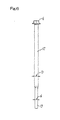
- Figs. 2(a) to 2(c) show the step of preparing a second part 30 also used herein.
- a shorter raw steel rod 31 having a diameter 'D1' greater than 'D' of the shank will be put at first in a first die 37.
- a preliminarily forming punch 38 will then press this raw rod 31 so as to force a bottom thereof into a swaged tapered end 32.
- An increased-diameter rod portion 35 thus prepared will have an end face 33 whose diameter is equal to 'D' and a body 34 whose diameter is 'D1' larger than 'D'.
- a top of such a raw rod is simultaneously forced to swell in a radial direction to provide an unfinished head 36'.
- the increased-diameter rod portion 35 will be fitted in a second die 40 as shown in Fig. 2(c).
- a finishing punch 41 will then press the unfinished head 36' into a finished shape 36 so that the increased-diameter rod portion 35 of second part 30 has a head 36 disposed at the top of this portion 25 having the diameter 'D1'.
- the reference numerals 39, 42 and 43 in the drawings respectively denote further ejecting pins.
- first and second parts 20 and 30 prepared in the manner described above will now be set in position.
- the non-threaded shank 22 of first part 20 has its top face abutting the bottom face of the increased-diameter rod portion 35 of second part 30.
- These top and bottom faces will then be electrically resistance-welded to each other so as to consolidate the first and second parts.
- the distal end of the fastening rod portion 23 will be subjected to the forming-by-compression process.
- This process as seen in Fig. 3(b) is well known in the art and is not detailed here, but a drill tip 24 will be formed at said end, producing a scrap 25 around the drill tip 25.
- a screw thread 35a shown in Fig. 3(c) will be formed on and around the increased-diameter rod portion 35 by the rolling process. It may be possible to carry out this step of forming the thread 35a prior to the former step of forming the drill tip 24 shown in Fig. 3(b).
- the threaded fastener 50 manufactured in the described manner is characterized by the remarkably enlarged diameter of its threaded and increased-diameter rod portion 35. This diameter is much greater than that of the thread of fastening rod portion 23 that a roof 8 and various loads applied thereto will now be more surely born by the fastener. Diameter of such a thicker and threaded rod portion 35 can easily be increased furthermore, merely by changing the diameter 'D1' of raw rod 31.
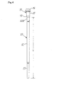
- Fig. 4 shows a modification of the method of making the fastener in accordance with the invention.
- a columnar extension 22a extends from the increased-diameter portion 35 of second part 30, across the tapered end 32 thereof. Diameter of this extension 22a is equal to that of the non-threaded shank 22.
- the columnar extension 22a formed integral with the second part 30 will enable production of extremely long fasteners 50.
- Such an extension 22a will have an effect of lengthening the non-threaded shank 22 and thus increasing overall length 'L' of the first part 20, even if this length exceeds the processing limit of the swaging die 26 in Fig. 1(b).
- the drill tip 24 is formed at the distal end of the threaded fastening rod portion 23 in the described embodiment. However, it may be replaced with the pointed end of any ordinary gimlet or the like boring means if the roofing panels 8 are attached to wooden beams or the like wooden building frames.
- the threaded fastener of the invention comprises such a proximal threaded rod portion adjacent to the head that the diameter of this portion can readily be increased.
- the increased-diameter threaded portion can now bear a much heavier load of the roofing panel itself or any external stress imparted thereto.
- the method of the invention as defined in claim 2 makes it feasible to manufacture such fasteners (for attaching the roofing panels) more efficiently and at a remarkably improved productivity.
Abstract
Description
- The present invention relates to a threaded fastener that may be used to attach roofing panels to beams or the like building frames, with a heat insulator intervening between the panels and the frames. The roofing panel typically of a folded shape may be made by bending a colored or stainless steel panel or the like raw panel to have parallel ridges each of a bottomless trapezoid pattern in cross section. The invention does also relate to a method of making such a threaded fastener.
- Reducing threaded fasteners 1 as best seen in Fig. 5 are and have been employed for the described purpose. Each of such fasteners 1 comprises a non-threaded elongate rod 2 having opposite ends, and a smaller-diameter threaded portion 3 continuing from one of the ends and disposed behind a boring means such as a drill tip 4. Each fastener 1 further comprises a larger-diameter threaded portion 5 continuing from the other end and formed with a head 6. Usually, a sealing washer 7 may be combined with the head 6 of the fastener 1 when the latter is used to attach the roofing panel to any structural part described above. The drill tip 4 piercing the
roofing panel 8 will produce therein ahole 9, before penetrating aheat insulating material 10. A metal frame 11 as one of the beams or the like building materials will then be bored by the drill tip 4 to provide a hole in said frame so that the smaller-diameter threaded portion 3 is screwed into and through the hole. Simultaneously, the larger-diameter threaded portion 5 will be screwed into the first mentionedhole 9 so as to cause the head 6 to press theroofing panel 8 at its outer surface, thereby securing this panel to the metal frame 11. In such a state of the members fastened to each other, the lower surface of saidroofing panel 8 is kept in a forced and tight engagement with the larger-diameter threaded portion 5. Thus, theroofing panel 8 can withstand well any strong wind pressure, any amount of snow lying on the roof and any body weight of a roofing worker usually treading same. In a case wherein the beams or the like building frames supporting theroofing panels 8 are wooden articles, the drill tip 4 may be replaced with another boring means such as a pointed gimlet. - A length of
raw rod 12 having a shank diameter 'D' may be used to make the roofing panel fixing fasteners I as summarized above, in a manner as shown in Fig. 6. One end portion of theraw rod 12 will be swaged to give athinned region 13 of a reduced diameter 'd' ready for subsequent formation of the smaller-diameter threaded portion 3. The other end of the raw rod will be pressed to give the proximal head 6, before rolling these end regions to producethreads 3a and 5a (see Fig. 5) around the smaller- and larger-diameter portions 3 and 5, respectively. It is required that the non-threaded elongate rod 2 can smoothly advance through thehole 9 formed in theroofing panel 8. Therefore, the shank diameter 'D' of this rod 2 has to be almost equal to or slightly less than the outer diameter of the thread 3a of the distal threaded portion 3. In other words, such a body diameter 'D' can not be made much greater than the reduced diameter 'd'.
Consequently, the outer diameter of larger-diameter portion 5 having itsthread 5a around theraw rod 12 cannot be much greater than the outer diameter of the thread 3a of distal threaded portion. In a typical example, the diameter of former threaded portion 5 is 6.2 mm and the latter threaded portion 3 has a diameter of 5.5 mm. - Recently, it has been required to reduce the number of those fasteners 1 necessary for attachment of one unit of the roofing panel. Therefore, each fastener must bear against as heavy a load as possible, by further increasing the diameter of threaded portion 5 adjacent to the proximal head 6. On the other hand,
thicker heat insulators 10 have been wanted to improve their effect of heat insulation. This has resulted in much longer non-threaded shanks 2. In order to simply thicken the proximal threaded portion 5 of such an elongated shank 2, a thicker raw rod 12' whose diameter 'D1' is considerably greater than that 'D' noted above has to be used as shown by the phantom lines in Fig. 7. Such a thickened raw rod 12' may be subject to the swaging process two times. The first step in this process will be conducted to form thenon-threaded shank 12 of the diameter 'D', with the second step further thinning same to provide an un-threadeddistal portion 13 of the diameter 'd' (see Fig. 6). However, this two-step swaging process is not only difficult to effectively carry out but also raises manufacture cost. Thus, such modified types of the roofing panel attaching fasteners have not been adapted for economical production. - The present invention was made in view of the drawbacks inherent in the prior art structure. An aspect of the invention is therefore to provide an elongate threaded fastener for attaching the roofing panels, improved such that a proximal threaded portion adjacent to a head of each fastener has a diameter that can readily be made as great as necessary, but not adversely affecting effective and economical production of the fasteners.
- According to an aspect of the invention, the present invention provides a threaded fastener for use to attach roofing panels such that the fastener comprises a first threaded part and a second threaded part, both made of a steel, wherein the first threaded part consists of an elongate non-threaded shank and a fastening rod portion continuing therefrom. A boring means such as a drill tip may be formed integral with the distal end of the fastening rod portion. The second threaded part consists of an increased-diameter rod portion that has a head at its proximal end and a screw thread formed on and around the increased-diameter portion to be capable of fixing in position the roofing panels. In the invention, the first and second threaded parts are resistance welded electrically so as to be firmly adjoined one to another.
- Preferably, the increased-diameter rod portion of the threaded fastener as summarized above may have an end face whose diameter is substantially equal to the diameter of the raw rod for the first part. This feature will enable a smoother and more uniform welding of the two parts abutting one another. A body of such a rod portion has consequently a diameter larger than that of said end face.
- The method provided in the present invention to make such a threaded fastener does characteristically comprise the preliminary step of preparing a first columnar part and a second columnar part, both made of the same or different steels, wherein the first part comprises an elongate non-threaded shank and a fastening rod portion continuing therefrom and of a reduced diameter, and the second part comprises an increased-diameter rod portion that has a head at its proximal end. The present method further comprises the succeeding steps of electrically resistance-welding the first and second parts to be firmly integral with each other, then forming a boring means such as a drill tip on the distal end of the fastening rod portion, and subsequently rolling both the fastening rod portion and increased-diameter rod portion so as to form screw threads respectively on and around these rod portions.
- In the present method, the increased-diameter rod portion may have a columnar extension continuing therefrom and of the same diameter as the elongate non-threaded shank, such that the extension is resistance welded to the non-threaded shank so as to firmly unite the first and second parts together.
-
- Fig. 1(a) is a front elevation of a raw material that is used to form a first part constituting a threaded fastener that is provided herein to attach the roofing panels;
- Fig. 1(b) is a front elevation of the raw material illustrated together with processing members shown fragmentarily and in cross section, that are employed at the step of forming the first part;
- Fig. 2(a) is a front elevation of a further raw material used to form a second part also in accordance with the present invention;
- Fig. 2(b) is a front elevation of the further raw material illustrated together with further processing members shown fragmentarily and in cross section, that are employed at the step of preparing the second part in its unfinished state;
- Fig. 2(c) is a front elevation of the raw material shown with still further processing members that are employed at the step of finishing the second part;
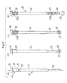
- Fig. 3(a) to 3(d) show the succeeding steps of making a threaded
fastener from the first and second parts, in which:
- Fig. 3(a) is a front elevation of the first and second parts at the step of adjoining them one to another;
- Fig. 3(b) is a front elevation of the first and second parts at the step of providing a drill tip integral with the first part by the forming-by-compression method;
- Fig. 3(c) is a front elevation of the first and second parts at the step of forming by the rolling method a screw thread on and around the increased-diameter rod portion of the second part; and
- Fig. 3(d) is a front elevation of the first and second parts at the step of forming by the rolling method another screw thread on and around the fastening rod portion of the first part, and then removing a scrap therefrom;
- Fig. 4 is a front elevation of raw materials that are being processed in a modified mode of the present method;
- Fig. 5 is a front elevation of the prior art threaded fastener used to attach the roofing panels, wherein the fastener is shown with relevant articles illustrated fragmentarily and in cross section;
- Fig. 6 is a front elevation of the prior art threaded fastener shown in its unfinished state; and
- Fig. 7 is likewise a front elevation of a modified type of the prior art threaded fastener also shown in its unfinished state.
-
- Now some embodiments of the present invention will be described in detail referring to the drawings.
- Figs. 1(a) and 1(b) illustrate the step of preparing a
first part 20 provided and used herein. A raw steel rod 21will be placed in a swaging die 26, and then apunch 28 descending through apunch guide 27 will press theraw rod 21 downwards. An elongate non-threadedshank 22 having a diameter 'D' is the main portion of the thus pressed rod. Afastening rod portion 23 having a reduced diameter 'd' continues from the bottom of saidshank 22 in thefirst part 20 formed in this manner. In the drawings, thereference numeral 29 denotes an ejecting pin. - Figs. 2(a) to 2(c) show the step of preparing a
second part 30 also used herein. As seen in Figs. 2(a) and 2(b), a shorterraw steel rod 31 having a diameter 'D1' greater than 'D' of the shank will be put at first in afirst die 37. A preliminarily forming punch 38 will then press thisraw rod 31 so as to force a bottom thereof into a swagedtapered end 32. An increased-diameter rod portion 35 thus prepared will have anend face 33 whose diameter is equal to 'D' and abody 34 whose diameter is 'D1' larger than 'D'. A top of such a raw rod is simultaneously forced to swell in a radial direction to provide an unfinished head 36'. Subsequently, the increased-diameter rod portion 35 will be fitted in asecond die 40 as shown in Fig. 2(c). A finishingpunch 41 will then press the unfinished head 36' into afinished shape 36 so that the increased-diameter rod portion 35 ofsecond part 30 has ahead 36 disposed at the top of thisportion 25 having the diameter 'D1'. The reference numerals 39, 42 and 43 in the drawings respectively denote further ejecting pins. - The first and
second parts non-threaded shank 22 offirst part 20 has its top face abutting the bottom face of the increased-diameter rod portion 35 ofsecond part 30. These top and bottom faces will then be electrically resistance-welded to each other so as to consolidate the first and second parts. Subsequent to this welding step rendering these parts 'one-piece', the distal end of thefastening rod portion 23 will be subjected to the forming-by-compression process. This process as seen in Fig. 3(b) is well known in the art and is not detailed here, but adrill tip 24 will be formed at said end, producing ascrap 25 around thedrill tip 25. - Thereafter, a
screw thread 35a shown in Fig. 3(c) will be formed on and around the increased-diameter rod portion 35 by the rolling process. It may be possible to carry out this step of forming thethread 35a prior to the former step of forming thedrill tip 24 shown in Fig. 3(b). - Finally, such an unfinished product will be subjected to a further rolling step to provide another screw thread 23a around the
fastening rod portion 23. Rotation of the unfinished product at this step is utilized to remove thescrap 25, thereby finishing the roofing panel-attachingfastener 50 of the invention. Details of scrap removing technique well known in the art are not given here, and it is possible to removescrap 25 while thethread 35a is formed on the increased-diameter portion 35. - The threaded
fastener 50 manufactured in the described manner is characterized by the remarkably enlarged diameter of its threaded and increased-diameter rod portion 35. This diameter is much greater than that of the thread offastening rod portion 23 that aroof 8 and various loads applied thereto will now be more surely born by the fastener. Diameter of such a thicker and threadedrod portion 35 can easily be increased furthermore, merely by changing the diameter 'D1' ofraw rod 31. - Fig. 4 shows a modification of the method of making the fastener in accordance with the invention. In this modification, a columnar extension 22a extends from the increased-
diameter portion 35 ofsecond part 30, across thetapered end 32 thereof. Diameter of this extension 22a is equal to that of thenon-threaded shank 22. - The columnar extension 22a formed integral with the
second part 30 will enable production of extremelylong fasteners 50. Such an extension 22a will have an effect of lengthening thenon-threaded shank 22 and thus increasing overall length 'L' of thefirst part 20, even if this length exceeds the processing limit of the swaging die 26 in Fig. 1(b). - The
drill tip 24 is formed at the distal end of the threadedfastening rod portion 23 in the described embodiment. However, it may be replaced with the pointed end of any ordinary gimlet or the like boring means if theroofing panels 8 are attached to wooden beams or the like wooden building frames. - In summary, the threaded fastener of the invention comprises such a proximal threaded rod portion adjacent to the head that the diameter of this portion can readily be increased. By virtue of this feature, the increased-diameter threaded portion can now bear a much heavier load of the roofing panel itself or any external stress imparted thereto.
- The method of the invention as defined in claim 2 makes it feasible to manufacture such fasteners (for attaching the roofing panels) more efficiently and at a remarkably improved productivity.
- The method defined in claim 3 will make it possible to manufacture certain extremely long fasteners of the described type.
Claims (4)
- A threaded fastener (50) for use in attaching roofing panels (8), the fastener comprising a first threaded part (20) and a second threaded part (30), both made of steel, wherein the first threaded part (20) consists of an elongate non-threaded shank (22) and a fastening rod portion (23) continuing therefrom, and a boring means (24) such as a drill tip may be formed integral with the distal end of the fastening rod portion (23),
CHARACTERIZED IN THAT the second threaded part (30) consists of an increased-diameter rod portion (35) that has a head (36) at its proximal end and a screw thread (35a) formed on and around the increased-diameter portion (35) to be capable of fixing in position the roofing panels (8), and the first and second threaded parts (20,30) are resistance welded electrically so as to be firmly adjoined one to another. - A threaded fastener as defined in claim 1, characterized in that the increased-diameter rod portion (35) has an end face (33) whose diameter is substantially equal to the diameter (D) of the raw rod (21) and a body (34) whose diameter (D1) is larger than that (D) of said end face (33).
- A method of making a threaded fastener (50) for use in attaching roofing panels (8), comprising: the preliminary step of preparing a first columnar part (20) and a second columnar part (30), both made of the same or different steels, wherein the first part (20) comprises an elongate non-threaded shank (22) and a fastening rod portion (23) continuing therefrom and of a reduced diameter,
CHARACTERIZED IN THAT the second part (30) comprises an increased-diameter rod portion (35) having a head (36) at its proximal end, the method further comprising the steps of electrically resistance-welding the first and second parts (20,30) to be firmly integral with each other, then forming a boring means (24) such as a drill tip on the distal end of the fastening rod portion (23), and subsequently rolling both the fastening rod portion (23) and increased-diameter rod portion (35) so as to form screw threads (23a,35a) respectively on and around these rod portions (23,35). - The method as defined in claim 3, characterized in that the increased-diameter rod portion (35) has a columnar extension (22a) continuing therefrom and of the same diameter as the elongate non-threaded shank (22), such that the extension (22a) is resistance welded to the non-threaded shank (22) so as to firmly unite the first and second parts (20,30) together.
Applications Claiming Priority (2)
| Application Number | Priority Date | Filing Date | Title |
|---|---|---|---|
| JP2000242066 | 2000-08-10 | ||
| JP2000242066A JP2002054618A (en) | 2000-08-10 | 2000-08-10 | Roof member installing screw, and method of manufacturing the same |
Publications (1)
| Publication Number | Publication Date |
|---|---|
| EP1180606A1 true EP1180606A1 (en) | 2002-02-20 |
Family
ID=18733147
Family Applications (1)
| Application Number | Title | Priority Date | Filing Date |
|---|---|---|---|
| EP01306580A Withdrawn EP1180606A1 (en) | 2000-08-10 | 2001-07-31 | Threaded fastener for use in attaching roofing panels and a method of making the fastener |
Country Status (3)
| Country | Link |
|---|---|
| US (1) | US20020018700A1 (en) |
| EP (1) | EP1180606A1 (en) |
| JP (1) | JP2002054618A (en) |
Cited By (8)
| Publication number | Priority date | Publication date | Assignee | Title |
|---|---|---|---|---|
| EP1418347A1 (en) * | 2002-11-06 | 2004-05-12 | Adolf Würth GmbH & Co. KG | Screw for adjustable spaced mounting |
| EP1450054A1 (en) * | 2003-02-20 | 2004-08-25 | Adolf Würth GmbH & Co. KG | Drilling screw |
| EP1884668A1 (en) * | 2006-08-04 | 2008-02-06 | Roto Frank Ag | Joining element for fixing a fitting to a wing or a fixed frame of a window, door or similar |
| EP1923151A1 (en) * | 2007-07-24 | 2008-05-21 | Top Well Tech Corp | Method of manufacturing a bi-metal screw |
| EP2014931A1 (en) * | 2008-04-04 | 2009-01-14 | Shu-Yun Chuang | Fastener with removable element |
| EP2092995A3 (en) * | 2008-02-25 | 2009-09-02 | Sun Through Industrial Co. Ltd. | Self-drilling screw and method of making the same |
| FR2930304A1 (en) * | 2008-04-17 | 2009-10-23 | Lr Etanco Soc Par Actions Simp | METHOD AND DEVICE FOR FASTENING EQUIPMENT ON A COMPRESSIBLE COATING COVERING A SUPPORT STRUCTURE |
| US9611882B2 (en) | 2013-09-11 | 2017-04-04 | Sfs Intec Holding Ag | Back-out resistant fastener |
Families Citing this family (5)
| Publication number | Priority date | Publication date | Assignee | Title |
|---|---|---|---|---|
| DE102006024440B4 (en) * | 2006-05-24 | 2008-05-29 | Ludwig Hettich & Co. | Screw |
| DE102012101320A1 (en) * | 2012-02-17 | 2013-08-22 | Sfs Intec Holding Ag | Screw and thin sheet metal connection made therewith |
| DE102017118013A1 (en) * | 2017-08-08 | 2019-02-14 | Adolf Würth Gmbh & Co Kg | Fastener with shaft of abutted sections of different diameters |
| EP3450647B1 (en) * | 2017-09-01 | 2021-08-11 | SFS Intec Holding AG | Fastener for insulation material |
| JP2019078153A (en) * | 2017-10-25 | 2019-05-23 | ヒロテツ工業株式会社 | Drill screw for folded-plate roof and folded-plate roof method |
Citations (5)
| Publication number | Priority date | Publication date | Assignee | Title |
|---|---|---|---|---|
| US398912A (en) * | 1889-03-05 | Method of manufacturing screws and bolts by electricity | ||
| US3924508A (en) * | 1974-09-27 | 1975-12-09 | Textron Inc | Composite drill screw |
| EP0129404A1 (en) * | 1983-06-15 | 1984-12-27 | ITW Limited | Fixings including screws and clamp plates |
| US4621963A (en) * | 1984-03-26 | 1986-11-11 | Elco Industries, Inc. | Fastener for roof assemblies and the like |
| EP0370674A1 (en) * | 1988-11-25 | 1990-05-30 | Yugen Kaisha Shinjoseisakusho | Drill screw |
-
2000
- 2000-08-10 JP JP2000242066A patent/JP2002054618A/en active Pending
-
2001
- 2001-07-30 US US09/917,153 patent/US20020018700A1/en not_active Abandoned
- 2001-07-31 EP EP01306580A patent/EP1180606A1/en not_active Withdrawn
Patent Citations (5)
| Publication number | Priority date | Publication date | Assignee | Title |
|---|---|---|---|---|
| US398912A (en) * | 1889-03-05 | Method of manufacturing screws and bolts by electricity | ||
| US3924508A (en) * | 1974-09-27 | 1975-12-09 | Textron Inc | Composite drill screw |
| EP0129404A1 (en) * | 1983-06-15 | 1984-12-27 | ITW Limited | Fixings including screws and clamp plates |
| US4621963A (en) * | 1984-03-26 | 1986-11-11 | Elco Industries, Inc. | Fastener for roof assemblies and the like |
| EP0370674A1 (en) * | 1988-11-25 | 1990-05-30 | Yugen Kaisha Shinjoseisakusho | Drill screw |
Cited By (10)
| Publication number | Priority date | Publication date | Assignee | Title |
|---|---|---|---|---|
| EP1418347A1 (en) * | 2002-11-06 | 2004-05-12 | Adolf Würth GmbH & Co. KG | Screw for adjustable spaced mounting |
| EP1450054A1 (en) * | 2003-02-20 | 2004-08-25 | Adolf Würth GmbH & Co. KG | Drilling screw |
| EP1884668A1 (en) * | 2006-08-04 | 2008-02-06 | Roto Frank Ag | Joining element for fixing a fitting to a wing or a fixed frame of a window, door or similar |
| EP2131047A3 (en) * | 2006-08-04 | 2011-04-06 | Roto Frank Ag | Connection element for attaching a fitting part to a leaf or a blind frame of a window, door or similar |
| EP1923151A1 (en) * | 2007-07-24 | 2008-05-21 | Top Well Tech Corp | Method of manufacturing a bi-metal screw |
| EP2092995A3 (en) * | 2008-02-25 | 2009-09-02 | Sun Through Industrial Co. Ltd. | Self-drilling screw and method of making the same |
| EP2014931A1 (en) * | 2008-04-04 | 2009-01-14 | Shu-Yun Chuang | Fastener with removable element |
| FR2930304A1 (en) * | 2008-04-17 | 2009-10-23 | Lr Etanco Soc Par Actions Simp | METHOD AND DEVICE FOR FASTENING EQUIPMENT ON A COMPRESSIBLE COATING COVERING A SUPPORT STRUCTURE |
| WO2009133305A1 (en) * | 2008-04-17 | 2009-11-05 | Ateliers Lr Etanco | Method and device for attaching an apparatus onto a compressible coating covering a mounting structure |
| US9611882B2 (en) | 2013-09-11 | 2017-04-04 | Sfs Intec Holding Ag | Back-out resistant fastener |
Also Published As
| Publication number | Publication date |
|---|---|
| JP2002054618A (en) | 2002-02-20 |
| US20020018700A1 (en) | 2002-02-14 |
Similar Documents
| Publication | Publication Date | Title |
|---|---|---|
| EP1180606A1 (en) | Threaded fastener for use in attaching roofing panels and a method of making the fastener | |
| EP0307119B1 (en) | Screw threaded fastener | |
| CA1248374A (en) | Wood screw | |
| DE602004000246T2 (en) | Method of making a crimped nut and crimping nut made by this method | |
| US4233878A (en) | Barb and method of making same | |
| US5743062A (en) | Anchoring device for housing/building construction | |
| DE3213605A1 (en) | TWO-PIECE FASTENER FOR LAYING WORKPIECES | |
| DE19653925C2 (en) | Method of manufacturing an assembly unit | |
| DE2057809A1 (en) | Rivet | |
| EP0766015B1 (en) | Method of manufacturing a housing of a joint | |
| JPH03161136A (en) | Manufacture of anchor bolt for concrete and its device for manufacture of anchor bolt | |
| DE102016204619A1 (en) | Press-in connection between a high-strength component and a press-in element, method for forming such a press-in connection and press-in element for such a press-in connection | |
| DE4112591C1 (en) | ||
| EP1181461B1 (en) | Blind Rivet for Structural Parts of Different Wall Thicknesses and Method for Producing such a Blind Rivet | |
| US3978758A (en) | Bolt and process of forming same | |
| US4572875A (en) | Blank for a thread forming screw | |
| EP1355751B1 (en) | Method for producing a housing for a ball joint | |
| EP0918165B1 (en) | Fastening screw and method of forming same | |
| DE19859208A1 (en) | Metal fastener and method of manufacture | |
| IE900269L (en) | Self-drilling blind rivet | |
| US20100003105A1 (en) | Method for producing a locking ring bolt and locking ring bolt | |
| US5353493A (en) | Method for manufacturing whip antenna | |
| US6558263B1 (en) | Forging method of a hollow part | |
| US4682381A (en) | Spike forming method | |
| US1933737A (en) | Method of making screws and bolts |
Legal Events
| Date | Code | Title | Description |
|---|---|---|---|
| PUAI | Public reference made under article 153(3) epc to a published international application that has entered the european phase |
Free format text: ORIGINAL CODE: 0009012 |
|
| AK | Designated contracting states |
Kind code of ref document: A1 Designated state(s): CH DE GB LI SE Kind code of ref document: A1 Designated state(s): AT BE CH CY DE DK ES FI FR GB GR IE IT LI LU MC NL PT SE TR |
|
| AX | Request for extension of the european patent |
Free format text: AL;LT;LV;MK;RO;SI |
|
| 17P | Request for examination filed |
Effective date: 20020718 |
|
| AKX | Designation fees paid |
Free format text: CH DE GB LI SE |
|
| 17Q | First examination report despatched |
Effective date: 20030416 |
|
| STAA | Information on the status of an ep patent application or granted ep patent |
Free format text: STATUS: THE APPLICATION IS DEEMED TO BE WITHDRAWN |
|
| 18D | Application deemed to be withdrawn |
Effective date: 20030827 |