EP1180592B1 - Stahlkolben - Google Patents
Stahlkolben Download PDFInfo
- Publication number
- EP1180592B1 EP1180592B1 EP20010117240 EP01117240A EP1180592B1 EP 1180592 B1 EP1180592 B1 EP 1180592B1 EP 20010117240 EP20010117240 EP 20010117240 EP 01117240 A EP01117240 A EP 01117240A EP 1180592 B1 EP1180592 B1 EP 1180592B1
- Authority
- EP
- European Patent Office
- Prior art keywords
- piston
- base part
- gap
- annular section
- projection
- Prior art date
- Legal status (The legal status is an assumption and is not a legal conclusion. Google has not performed a legal analysis and makes no representation as to the accuracy of the status listed.)
- Expired - Lifetime
Links
Images

Classifications
-
- F—MECHANICAL ENGINEERING; LIGHTING; HEATING; WEAPONS; BLASTING
- F02—COMBUSTION ENGINES; HOT-GAS OR COMBUSTION-PRODUCT ENGINE PLANTS
- F02F—CYLINDERS, PISTONS OR CASINGS, FOR COMBUSTION ENGINES; ARRANGEMENTS OF SEALINGS IN COMBUSTION ENGINES
- F02F3/00—Pistons
- F02F3/0015—Multi-part pistons
- F02F3/003—Multi-part pistons the parts being connected by casting, brazing, welding or clamping
-
- F—MECHANICAL ENGINEERING; LIGHTING; HEATING; WEAPONS; BLASTING
- F05—INDEXING SCHEMES RELATING TO ENGINES OR PUMPS IN VARIOUS SUBCLASSES OF CLASSES F01-F04
- F05C—INDEXING SCHEME RELATING TO MATERIALS, MATERIAL PROPERTIES OR MATERIAL CHARACTERISTICS FOR MACHINES, ENGINES OR PUMPS OTHER THAN NON-POSITIVE-DISPLACEMENT MACHINES OR ENGINES
- F05C2201/00—Metals
- F05C2201/04—Heavy metals
- F05C2201/0433—Iron group; Ferrous alloys, e.g. steel
- F05C2201/0448—Steel
Definitions
- the invention relates to a piston for an internal combustion engine according to the features of the preamble of claim 1.
- a piston for an internal combustion engine is known from EP 0 804 680 B1, in which a ring section or a lower part of the ring section is connected to the piston crown or an upper part of the ring section via a welding or soldering process. Through the ring section and the piston crown (base part) creates a circumferential, downwardly free space, which is closed by a component, so that a cooling channel is formed.
- a piston is also known, in which a ring portion is welded to a base part of the piston. A circumferential wall of the base part and the component welded to the base part together form a radially outer and an axial-lower boundary wall of a cooling channel.
- This piston has a plurality of holes directed into the cooling channel, via which the cooling channel is supplied with a cooling medium, in particular engine oil. This cooling medium is injected by appropriate means into the piston inner region and fed via the bores to the cooling channel. The drain also takes place via these holes.
- the cooling channel has the purpose that is cooled by the coolant channel flowing through the cooling medium, in particular engine oil, the piston crown area to protect it from damage due to high Brennraumtemparaturen.
- the cooling medium in particular engine oil
- DE 36 43 039 A1 or DE 198 46 152 A1 existing between the cooling channel and the interior of the piston holes represent an additional manufacturing step. At the same time, these holes are located at a point in the piston, which weakens the strength of the piston.
- the invention is therefore based on the object to simplify a piston for an internal combustion engine in terms of its production, without the stability is reduced.
- At least one further opening in particular a circumferential gap, is present.
- this opening the cooling medium can be removed from the cooling channel, so that can be dispensed with additional holes in the piston except the opening for the supply of the cooling medium.
- the supply of the cooling medium takes place in an advantageous manner via at least one opening, which is likewise provided in the ring section.
- the gap is formed by the attachment and the shape of the ring portion with respect to the base part. This means that the ring portion and the corresponding region of the base part are matched to one another such that after attachment of the ring portion, the gap arises by itself. Work steps for introducing the gap are thus eliminated altogether.
- the further opening in particular the gap, is introduced after the attachment of the ring section to the base part.
- the shape of the ring portion and the corresponding shape of the base part are coordinated so that after attachment of the ring portion of the cooling channel is largely or completely closed.
- the introduction of the at least one further opening (of the gap) takes place, wherein it may also be instead of a circumferential gap to several holes or teilumfnature columns.
- this requires a further operation, however, it can be accepted because the opening for the purpose of supplying the cooling medium is arranged in a region of the piston through which the piston crown region is not weakened.
- the ring section can be attached to the base part by means of a welding method. This can be mounted on the base part in a simple and known manner, the ring portion after its production. Base part and ring section can both be produced by casting, for example.
- the piston is preferably made of steel.
- a weld joint is arranged in alignment with the gap. This has the advantage that the joint and the gap region of the base part can be machined prior to attachment of the ring portion with the same degree.
- Figure 1 shows a detail of the bottom portion of a piston for an internal combustion engine. It is a pendulum piston. The remainder of the design of the piston is not important, for the sake of completeness reference is made to the construction of a piston on FIG. 1 together with the associated description of EP 0 804 680 B1 or FIG. 1 together with the associated description of DE 198 46 152 A1.
- the piston shown in Figure 1 has a base part 1, wherein in the bottom region of a combustion bowl 2 is present.
- a prefabricated ring section 3, which later carries the piston rings, is attached to the base part by means of a welding process in the region of a welding joint 4.
- the ring portion 3 has a web 5, which is directed in the direction of the base part 1, but does not come to rest on this, so that the web 5 and the corresponding region of the base part 1 form a gap 6.
- a cooling channel 7, which is also formed by the shape of the base part 1 and the ring portion 3, cooling medium, such as engine oil, are supplied.
- the gap 6 is shown larger in the figures for the purpose of illustrating the geometric configuration than in reality.
- the gap 6, that is, the gap, or even the size of the one or more openings, is to be chosen so that an optimal volume flow into thedeknanal 7 in and is given out in particular on the gap 6 out.
- the cooling medium sufficiently long time in the cooling channel 7 remains to absorb the heat, and is discharged in good time.
- the ring portion 3 can be pushed from below, so over the piston shaft, in its end position, since the inner diameter of the ring portion 3 in the region of the web fifth it is not allowed to push the ring section 3 over the floor area. This is possible with pendulum piston, since the diameter in the region of the piston shaft is smaller than the inner diameter in the region of the web fifth
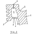
- Figure 2 shows a similar construction of a piston as in Figure 1, but with the difference that both the base part 1 and the ring portion 3 each have mutually facing projections 8 and 9, which form the gap 6.
- the projections 8 and. 9 can be the same or different lengths.
- the welding joint 4 and the gap 6 are in alignment, thereby simplifying the machining of the components involved.
- a construction shown in FIG. 2 can be realized both in the case of pendulum and monobloc pistons, since the inner diameter in the area of the projection 9 (after the final assembly of the ring section 3 on the base part 1) is in any case equal to or greater than the diameter of the bottom area without the ring section 3.
- the front side of the projection 9 can exceed the vertical line to the left, both in the case of pendulum piston and monoblock piston.
- the ring portion has an at least opening through which the cooling medium is injected by suitable means in the internal combustion engine in the cooling channel. This opening and the funds are available in any case.
Landscapes
- Engineering & Computer Science (AREA)
- Chemical & Material Sciences (AREA)
- Combustion & Propulsion (AREA)
- Mechanical Engineering (AREA)
- General Engineering & Computer Science (AREA)
- Pistons, Piston Rings, And Cylinders (AREA)
Description
- Die Erfindung betrifft einen Kolben für eine Brennkraftmaschine gemäß den Merkmalen des Oberbegriffes des Patentanspruches 1.
- Aus der EP 0 804 680 B1 ist ein Kolben für eine Brennkraftmaschine bekannt, bei dem ein Ringabschnitt oder ein unterer Teil des Ringabschnittes über ein Schweiß- oder Lötverfahren mit dem Kolbenboden bzw. einem oberen Teil des Ringabschnittes verbunden ist. Durch den Ringabschnitt und den Kolbenboden (Basisteil) entsteht ein umlaufender, nach unten freier Raum, der durch ein Bauteil verschlossen wird, so daß ein Kühlkanal entsteht.
- Aus der DE 36 43 039 A1 oder der DE 198 46 152 A1 ist ebenfalls ein Kolben bekannt, bei dem ein Ringabschnitt an ein Basisteil des Kolbens angeschweißt wird. Eine umlaufende Wand des Basisteils und das mit dem Basisteil verschweißte Bauteil bilden gemeinsam eine radial-äußere und axial-untere Begrenzungswand eines Kühlkanals. Dieser Kolben weist mehrere in den Kühlkanal gerichtete Bohrungen auf, über welche der Kühlkanal mit einem Kühlmedium, insbesondere Motoröl, versorgt wird. Dieses Kühlmedium wird mit entsprechenden Mitteln in den Kolbeninnenbereich gespritzt und über die Bohrungen dem Kühlkanal zugeführt. Der Abfluß erfolgt ebenfalls über diese Bohrungen.
- Der Kühlkanal hat den Zweck, daß durch das den Kühlkanal durchströmende Kühlmedium, insbesondere Motoröl, der Kolbenbodenbereich gekühlt wird, um ihn vor Beschädigungen infolge hoher Brennraumtemparaturen zu schützen. Bei den bekannten Bauarten der Kolben ist es erforderlich, den Kühlkanal mit einer Öffnung zu versehen, durch welche das Kühlmedium in den Kühlkanal strömen kann. So stellen die bei der DE 36 43 039 A1 oder der DE 198 46 152 A1 zwischen dem Kühlkanal und dem Innenbereich des Kolbens vorhandenen Bohrungen einen zusätzlichen Herstellungsschritt dar. Gleichzeitig befinden sich diese Bohrungen an einer Stelle im Kolben, die die Festigkeit des Kolbens schwächt.
- Der Erfindung liegt daher die Aufgabe zugrunde, einen Kolben für eine Brennkraftmaschine hinsichtlich seiner Herstellung zu vereinfachen, ohne daß die Stabilität verringert wird.
- Diese Aufgabe ist durch die Merkmale des Patentanspruches 1 gelöst.
- Es ist vorgesehen, daß nach der Endbearbeitung des Kolbens zwischen dem Basisteil und dem Ringabschnitt zumindest eine weitere Öffnung, insbesondere ein umlaufender Spalt, vorhanden ist. Durch diese Öffnung (diesen Spalt) kann das Kühlmedium aus dem Kühlkanal abgeführt werden, so daß außer der Öffnung für die Zufuhr des Kühlmediums auf zusätzliche Bohrungen im Kolben verzichtet werden kann. Die Zufuhr des Kühlmediums erfolgt in vorteilhafter über zumindest eine Öffnung, die ebenfalls in dem Ringabschnitt vorgesehen ist. Dadurch sind sämtliche Öffnungen, gleich welcher geometrischer Form, in einem Bereich des Kolbens angeordnet, durch den die Festigkeit des Kolbens nicht beeinträchtigt ist. Die Anordnung einer Öffnung im Basisteil kann damit vermieden werden.
- In Weiterbildung der Erfindung entsteht der Spalt durch die Anbringung und die Form des Ringabschnittes in Bezug auf das Basisteil. Das bedeutet, daß der Ringabschnitt und der korrespondierende Bereich des Basisteils derart aufeinander abgestimmt sind, daß nach Anbringung des Ringabschnittes der Spalt von alleine entsteht. Arbeitsschritte zur Einbringung des Spaltes entfallen damit gänzlich.
- In einer alternativen Ausgestaltung der Erfindung wird die weitere Öffnung, insbesondere der Spalt, nach der Anbringung des Ringabschnittes an dem Basisteil eingebracht. Das bedeutet, daß die Form des Ringabschnittes und die korrespondierende Form des Basisteils so aufeinander abgestimmt sind, daß nach Anbringung des Ringabschnittes der Kühlkanal weitestgehend oder vollständig geschlossen ist. Anschließend erfolgt die Einbringung der zumindest einen weiteren Öffnung (des Spaltes), wobei es sich auch anstelle eines umlaufenden Spaltes um mehrere Bohrungen oder teilumfängliche Spalten handeln kann. Hierdurch wird zwar ein weiterer Arbeitsschritt erforderlich, der jedoch deshalb in Kauf genommen werden kann, weil die Öffnung zwecks Zuführung des Kühlmediums in einem Bereich des Kolbens angeordnet ist, durch welchen der Kolbenbodenbereich nicht geschwächt wird.
- In Weiterbildung der Erfindung ist der Ringabschnitt mittels eines Schweißverfahrens an dem Basisteil anbringbar. Damit kann auf einfache und an sich bekannte Art und Weise der Ringabschnitt nach seiner Herstellung an dem Basisteil angebracht werden. Basisteil und Ringabschnitt können beispielsweise beide im Gießverfahren hergestellt werden. Der Kolben besteht vorzugsweise aus Stahl.
- In Weiterbildung der Erfindung ist eine Schweißfuge in einer Flucht mit dem Spalt angeordnet. Dies hat den Vorteil, daß der Fugen- und der Spaltbereich des Basisteiles vor Anbringung des Ringabschnittes mit dem gleichen Maß bearbeitet werden kann.
- Zwei Ausführungsbeispiele der vorliegenden Erfindung, auf die diese jedoch nicht beschränkt ist, sind im folgenden beschrieben und anhand der Figuren erläutert.
- Es zeigen:
- Figur 1:
- einen Kolben, bei dem ein Ringabschnitt einen Steg aufweist und
- Figur 2:
- einen Kolben, bei dem sowohl der Ringabschnitt als auch das Basisteil einen Vorsprung aufweisen.
- Figur 1 zeigt ausschnittsweise den Bodenbereich eines Kolbens für eine Brennkraftmaschine. Es handelt sich hierbei um einen Pendelschaftkolben. Auf die übrige Bauart des Kolbens kommt es nicht an, wobei der Vollständigkeit halber auf den Aufbau eines Kolbens auf die Figur 1 nebst zugehöriger Beschreibung der EP 0 804 680 B1 bzw. die Figur 1 nebst zugehöriger Beschreibung der DE 198 46 152 A1 verwiesen wird.
- Der in Figur 1 gezeigte Kolben weist ein Basisteil 1 auf, wobei im Bodenbereich eine Brennraummulde 2 vorhanden ist. Ein vorgefertigter Ringabschnitt 3, der später die Kolbenringe trägt, wird mittels eines Schweißverfahrens im Bereich einer Schweißfuge 4 an dem Basisteil angebracht. Der Ringabschnitt 3 weist einen Steg 5 auf, der in Richtung des Basisteiles 1 gerichtet ist, aber an diesem nicht zur Anlage kommt, so daß der Steg 5 und der korrespondierende Bereich des Basisteiles 1 einen Spalt 6 bilden. Über diesen Spalt 6 kann einem Kühlkanal 7, der ebenfalls durch die Form des Basisteiles 1 und des Ringabschnittes 3 gebildet ist, Kühlmedium, wie Motoröl, zugeführt werden. Der Spalt 6 ist in den Figuren zwecks Verdeutlichung der geometrischen Ausgestaltung größer dargestellt als in der Realität. Der Spalt 6, das heißt das Spaltmaß, oder aber auch die Größe der einen Öffnung oder mehrerer Öffnungen, ist dabei so zu wählen, daß ein optimaler Volumenfluß in den Kühlknanal 7 hinein und insbesondere über den Spalt 6 heraus gegeben ist. Denn es ist anzustreben, daß das Kühlmedium ausreichend lange Zeit im Kühlkanal 7 verbleibt, um die Wärme aufzunehmen, und rechtzeitig wieder abgeführt wird.
Der Ringabschnitt 3 kann von unten, also über den Kolbenschaft, in seine Endposition geschoben werden, da der Innendurchmesser des Ringabschnittes 3 im Bereich des Steges 5 es nicht gestattet, den Ringabschnitt 3 über den Bodenbereich zu schieben. Dies ist bei Pendelschaftkolben möglich, da der Durchmesser im Bereich des Kolbenschaftes kleiner ist als der Innendurchmesser im Bereich des Steges 5. - Figur 2 zeigt einen ähnlichen Aufbau eines Kolbens wie in Figur 1, jedoch mit dem Unterschied, daß sowohl das Basisteil 1 als auch der Ringabschnitt 3 jeweils einander zugewandte Vorsprünge 8 und 9 aufweisen, die den Spalt 6 bilden. Die Vorsprünge 8 und. 9 können gleich oder unterschiedlich lang sein. In bevorzugter Ausgestaltung liegen die Schweißfuge 4 und der Spalt 6 in einer Flucht, so daß dadurch die Bearbeitung der beteiligten Bauteile vereinfacht wird.
Ein in Figur 2 gezeigter Aufbau ist realisierbar sowohl bei Pendelschaft- als auch bei Monoblockkolben, da der Innendurchmesser im Bereich des Vorsprunges 9 (nach der Endmontages des Ringabschnittes 3 auf dem Basisteil 1) auf jeden Fall gleich oder größer ist als der Durchmesser des Bodenbereiches ohne den Ringabschnitt 3. Bei Betrachtung der Figur 2 bedeutet dies, daß, wenn eine senkrechte Linie durch die Schweißfuge 4 gezogen wird, die Stirnseite des Vorsprunges 8 maximal von rechts und die Stirnseite des Vorsprunges 9 maximal von links, unter Bildung des Spaltes 6, an die senkrechte Linie heranreicht. Dies entspricht insbesondere den geometrischen Verhältnissen bei Monoblockkolben, da bei dieser Bauart der Ringabschnitt 3 nur, bei Betrachtung der Figur 2, von oben über den Kolbenbodenbereich aufgeschoben werden kann, wobei die Stirnseite des Vorsprunges 9 nicht nach rechts die senkrechte Linie überschreiten darf. Hingegen kann die Stirnseite des Vorsprunges 9 sowohl bei Pendelschaftkolben als auch bei Monoblockkolben die senkrechte Linie nach links überschreiten. - In den Figuren ist nicht gezeigt, daß der Ringabschnitt eine zumindest Öffnung aufweist, über die das Kühlmedium mittels geeigneter Mittel in der Brennkraftmaschine in den Kühlkanal eingespritzt wird. Diese Öffnung und die Mittel sind aber auf jeden Fall vorhanden.
Claims (7)
- Kolben für eine Brennkraftmaschine, wobei der Kolben zumindest aus einem Basisteil (1) und einem daran angebrachten Ringabschnitt (3) besteht und das Basisteil (1) mit dem Ringabschnitt (3) einen Kühlkanal (7) bildet, wobei dem Kühlkanal (7) über eine Öffnung ein Kühlmedium zuführbar ist, dadurch gekennzeichnet, daß nach der Endbearbeitung des Kolbens zwischen dem Basisteil (1) und dem Ringabschnitt (3) zumindest eine weitere Öffnung, insbesondere ein umlaufender Spalt (6), vorhanden ist.
- Kolben nach Anspruch 1, dadurch gekennzeichnet, daß der Spalt (6) durch die Anbringung und die Form des Ringabschnittes (3) in Bezug auf das Basisteil (1) entsteht.
- Kolben nach Anspruch 1, dadurch gekennzeichnet, daß die weitere Öffnung, insbesondere der Spalt (6), nach der Anbringung des Ringabschnittes (3) an dem Basisteil (1) eingebracht wird.
- Kolben nach Anspruch 1 bis 3, dadurch gekennzeichnet, daß der Ringabschnitt (3) mittels eines Schweißverfahrens an dem Bauteil (1) anbringbar ist.
- Kolben nach einem der vorhergehenden Ansprüche, dadurch gekennzeichnet, daß eine Schweißfuge (4) in einer Flucht mit dem Spalt (6) angeordnet ist.
- Kolben nach einem der vorhergehenden Ansprüche, dadurch gekennzeichnet, daß zumindest an dem Ringabschnitt (3) ein in Richtung des Basisteiles (1) ausgerichteter Vorsprung (5) angeordnet ist, der zusammen mit der Wandung des Basisteiles (1) die weitere Öffnung, insbesondere den Spalt (6), bildet.
- Kolben nach Anspruch 6, dadurch gekennzeichnet, daß das Basisteil (1) einen den Spalt (6) zusammen mit dem Vorsprung (5) bildenden Vorsprung (8) aufweist.
Applications Claiming Priority (2)
| Application Number | Priority Date | Filing Date | Title |
|---|---|---|---|
| DE2000140486 DE10040486C2 (de) | 2000-08-18 | 2000-08-18 | Stahlkolben |
| DE10040486 | 2000-08-18 |
Publications (3)
| Publication Number | Publication Date |
|---|---|
| EP1180592A2 EP1180592A2 (de) | 2002-02-20 |
| EP1180592A3 EP1180592A3 (de) | 2002-09-11 |
| EP1180592B1 true EP1180592B1 (de) | 2006-03-15 |
Family
ID=7652919
Family Applications (1)
| Application Number | Title | Priority Date | Filing Date |
|---|---|---|---|
| EP20010117240 Expired - Lifetime EP1180592B1 (de) | 2000-08-18 | 2001-07-17 | Stahlkolben |
Country Status (2)
| Country | Link |
|---|---|
| EP (1) | EP1180592B1 (de) |
| DE (2) | DE10040486C2 (de) |
Families Citing this family (8)
| Publication number | Priority date | Publication date | Assignee | Title |
|---|---|---|---|---|
| DE102009041392A1 (de) | 2009-09-12 | 2011-05-26 | Daimler Ag | Kolben für eine Verbrennungskraftmaschine |
| DE102010056220A1 (de) * | 2010-12-24 | 2012-06-28 | Mahle International Gmbh | Kolben für einen Verbrennungsmotor |
| DE102010056218A1 (de) * | 2010-12-24 | 2012-06-28 | Mahle International Gmbh | Kolben für einen Verbrennungsmotor |
| DE102012014193A1 (de) * | 2012-07-18 | 2014-05-15 | Mahle International Gmbh | Kolben für einen Verbrennungsmotor |
| DE102013009164A1 (de) | 2013-05-31 | 2014-12-04 | Mahle International Gmbh | Kolben für einen Verbrennungsmotor |
| DE102013009161A1 (de) * | 2013-05-31 | 2014-12-18 | Mahle International Gmbh | Kolben für einen Verbrennungsmotor |
| DE102015212445A1 (de) | 2014-07-02 | 2016-01-07 | Ks Kolbenschmidt Gmbh | Spaltgeometrie bei einem stoffschlüssig gefügten Kühlkanalkolben |
| CN109312688A (zh) | 2016-05-04 | 2019-02-05 | Ks科尔本施密特有限公司 | 活塞 |
Family Cites Families (4)
| Publication number | Priority date | Publication date | Assignee | Title |
|---|---|---|---|---|
| DD123962A1 (de) * | 1975-12-24 | 1977-01-26 | ||
| DE3643039A1 (de) * | 1986-12-17 | 1988-06-30 | Mahle Gmbh | Kuehlbarer tauchkolben fuer verbrennungsmotoren |
| DE19501416A1 (de) * | 1995-01-19 | 1996-07-25 | Kolbenschmidt Ag | Geschmiedeter oder gegossener Kolbenkopf eines mehrteiligen Kolbens |
| DE19846152A1 (de) * | 1998-10-07 | 2000-04-13 | Mahle Gmbh | Kolben mit Kolbengrundkörper aus geschmiedetem Stahl und einem Kühlkanal |
-
2000
- 2000-08-18 DE DE2000140486 patent/DE10040486C2/de not_active Revoked
-
2001
- 2001-07-17 DE DE50109197T patent/DE50109197D1/de not_active Expired - Lifetime
- 2001-07-17 EP EP20010117240 patent/EP1180592B1/de not_active Expired - Lifetime
Also Published As
| Publication number | Publication date |
|---|---|
| DE50109197D1 (de) | 2006-05-11 |
| EP1180592A2 (de) | 2002-02-20 |
| EP1180592A3 (de) | 2002-09-11 |
| DE10040486C2 (de) | 2002-10-31 |
| DE10040486A1 (de) | 2002-03-07 |
Similar Documents
| Publication | Publication Date | Title |
|---|---|---|
| DE69306025T2 (de) | Konstruktion eines Brennkammerdomes | |
| EP1546535A1 (de) | Mehrteiligen gekühlten kolben für einen verbrennungsmotor | |
| DE10113993B4 (de) | Verbindungselement für eine Raupenkettenanordnung und Kettengliedanordnung für eine Raupenkette | |
| DE4112576A1 (de) | Verfahren zur herstellung eines kolbens und nach diesem verfahren hergestellter kolben | |
| DE3521206C2 (de) | ||
| DE10244511A1 (de) | Mehrteiliger gekühlter Kolben für einen Verbrennungsmotor | |
| DE4134529C2 (de) | Verfahren zur Herstellung eines Kolbenkopfes mit Kühlkammer und nach diesem Verfahren hergestellter Kolbenkopf | |
| DE19846152A1 (de) | Kolben mit Kolbengrundkörper aus geschmiedetem Stahl und einem Kühlkanal | |
| DE10352244A1 (de) | Verfahren zur Herstellung eines Kolbens für einen Verbrennungsmotor | |
| DE102004031513A1 (de) | Verfahren zur Herstellung eines Kühlkanalkolbens für eine Brennkraftmaschine | |
| DE10000952B4 (de) | Ölfilter und Herstellungsverfahren für denselben | |
| DE10209168B4 (de) | Stahlkolben mit Kühlkanal | |
| EP1926902A1 (de) | Kolben, insbesondere kühlkanalkolben, mit drei reibschweisszonen | |
| DE10040486C2 (de) | Stahlkolben | |
| DE10218999B4 (de) | Kolben mit Ringträger und Formkühlkanal | |
| DE19536349C1 (de) | Zusammengesetzte Kurbelwelle | |
| DE102021203241A1 (de) | Kolben für eine Brennkraftmaschine und Verfahren zur Herstellung des Kolbens | |
| DE10015709B4 (de) | Kolben mit einem ringförmigen Kühlkanal | |
| EP1924765A1 (de) | Kolben, insbesondere kühlkanalkolben einer brennkraftmaschine mit zumindest drei reibschweisszonen | |
| DE19715016A1 (de) | Zweiteiliges Gehäuse und Verfahren zu seiner Fertigung | |
| DE102004038464A1 (de) | Kolben, insbesondere Kühlkanalkolben, mit drei Reibschweißzonen | |
| DE10047258A1 (de) | Kolben mit sich am Basisteil abstützenden und angeschweißtem Ringabschnitt | |
| DE102004038465A1 (de) | Kolben, insbesondere Kühlkanalkolben einer Brennkraftmaschine, mit zumindest drei Reibschweißzonen | |
| EP0624414A1 (de) | Verfahren zum Herstellen einer Kurbelwelle | |
| DE10132447A1 (de) | Kolben mit angeschweißter Abdeckung des Kühlkanals |
Legal Events
| Date | Code | Title | Description |
|---|---|---|---|
| PUAI | Public reference made under article 153(3) epc to a published international application that has entered the european phase |
Free format text: ORIGINAL CODE: 0009012 |
|
| 17P | Request for examination filed |
Effective date: 20010717 |
|
| AK | Designated contracting states |
Kind code of ref document: A2 Designated state(s): AT BE CH CY DE DK ES FI FR GB GR IE IT LI LU MC NL PT SE TR |
|
| AX | Request for extension of the european patent |
Free format text: AL;LT;LV;MK;RO;SI |
|
| PUAL | Search report despatched |
Free format text: ORIGINAL CODE: 0009013 |
|
| AK | Designated contracting states |
Kind code of ref document: A3 Designated state(s): AT BE CH CY DE DK ES FI FR GB GR IE IT LI LU MC NL PT SE TR |
|
| AX | Request for extension of the european patent |
Free format text: AL;LT;LV;MK;RO;SI |
|
| RIC1 | Information provided on ipc code assigned before grant |
Free format text: 7F 02F 3/00 A, 7F 02F 3/22 B |
|
| AKX | Designation fees paid |
Designated state(s): DE FR GB IT SE |
|
| GRAP | Despatch of communication of intention to grant a patent |
Free format text: ORIGINAL CODE: EPIDOSNIGR1 |
|
| GRAS | Grant fee paid |
Free format text: ORIGINAL CODE: EPIDOSNIGR3 |
|
| GRAA | (expected) grant |
Free format text: ORIGINAL CODE: 0009210 |
|
| AK | Designated contracting states |
Kind code of ref document: B1 Designated state(s): DE FR GB IT SE |
|
| PG25 | Lapsed in a contracting state [announced via postgrant information from national office to epo] |
Ref country code: IT Free format text: LAPSE BECAUSE OF FAILURE TO SUBMIT A TRANSLATION OF THE DESCRIPTION OR TO PAY THE FEE WITHIN THE PRESCRIBED TIME-LIMIT;WARNING: LAPSES OF ITALIAN PATENTS WITH EFFECTIVE DATE BEFORE 2007 MAY HAVE OCCURRED AT ANY TIME BEFORE 2007. THE CORRECT EFFECTIVE DATE MAY BE DIFFERENT FROM THE ONE RECORDED. Effective date: 20060315 |
|
| REG | Reference to a national code |
Ref country code: GB Ref legal event code: FG4D Free format text: NOT ENGLISH |
|
| GBT | Gb: translation of ep patent filed (gb section 77(6)(a)/1977) |
Effective date: 20060315 |
|
| REF | Corresponds to: |
Ref document number: 50109197 Country of ref document: DE Date of ref document: 20060511 Kind code of ref document: P |
|
| PG25 | Lapsed in a contracting state [announced via postgrant information from national office to epo] |
Ref country code: SE Free format text: LAPSE BECAUSE OF FAILURE TO SUBMIT A TRANSLATION OF THE DESCRIPTION OR TO PAY THE FEE WITHIN THE PRESCRIBED TIME-LIMIT Effective date: 20060615 |
|
| ET | Fr: translation filed | ||
| PLBE | No opposition filed within time limit |
Free format text: ORIGINAL CODE: 0009261 |
|
| STAA | Information on the status of an ep patent application or granted ep patent |
Free format text: STATUS: NO OPPOSITION FILED WITHIN TIME LIMIT |
|
| 26N | No opposition filed |
Effective date: 20061218 |
|
| PGFP | Annual fee paid to national office [announced via postgrant information from national office to epo] |
Ref country code: FR Payment date: 20090716 Year of fee payment: 9 |
|
| PGFP | Annual fee paid to national office [announced via postgrant information from national office to epo] |
Ref country code: GB Payment date: 20090720 Year of fee payment: 9 |
|
| GBPC | Gb: european patent ceased through non-payment of renewal fee |
Effective date: 20100717 |
|
| REG | Reference to a national code |
Ref country code: FR Ref legal event code: ST Effective date: 20110331 |
|
| PG25 | Lapsed in a contracting state [announced via postgrant information from national office to epo] |
Ref country code: FR Free format text: LAPSE BECAUSE OF NON-PAYMENT OF DUE FEES Effective date: 20100802 |
|
| PG25 | Lapsed in a contracting state [announced via postgrant information from national office to epo] |
Ref country code: GB Free format text: LAPSE BECAUSE OF NON-PAYMENT OF DUE FEES Effective date: 20100717 |
|
| PGFP | Annual fee paid to national office [announced via postgrant information from national office to epo] |
Ref country code: DE Payment date: 20140721 Year of fee payment: 14 |
|
| REG | Reference to a national code |
Ref country code: DE Ref legal event code: R119 Ref document number: 50109197 Country of ref document: DE |
|
| PG25 | Lapsed in a contracting state [announced via postgrant information from national office to epo] |
Ref country code: DE Free format text: LAPSE BECAUSE OF NON-PAYMENT OF DUE FEES Effective date: 20160202 |