EP1180485A1 - A positioning device for ceramic articles - Google Patents
A positioning device for ceramic articles Download PDFInfo
- Publication number
- EP1180485A1 EP1180485A1 EP01306916A EP01306916A EP1180485A1 EP 1180485 A1 EP1180485 A1 EP 1180485A1 EP 01306916 A EP01306916 A EP 01306916A EP 01306916 A EP01306916 A EP 01306916A EP 1180485 A1 EP1180485 A1 EP 1180485A1
- Authority
- EP
- European Patent Office
- Prior art keywords
- shaped body
- ceramic shaped
- chucking
- ceramic
- positioning system
- Prior art date
- Legal status (The legal status is an assumption and is not a legal conclusion. Google has not performed a legal analysis and makes no representation as to the accuracy of the status listed.)
- Granted
Links
Images


Classifications
-
- B—PERFORMING OPERATIONS; TRANSPORTING
- B65—CONVEYING; PACKING; STORING; HANDLING THIN OR FILAMENTARY MATERIAL
- B65G—TRANSPORT OR STORAGE DEVICES, e.g. CONVEYORS FOR LOADING OR TIPPING, SHOP CONVEYOR SYSTEMS OR PNEUMATIC TUBE CONVEYORS
- B65G47/00—Article or material-handling devices associated with conveyors; Methods employing such devices
- B65G47/22—Devices influencing the relative position or the attitude of articles during transit by conveyors
-
- B—PERFORMING OPERATIONS; TRANSPORTING
- B23—MACHINE TOOLS; METAL-WORKING NOT OTHERWISE PROVIDED FOR
- B23Q—DETAILS, COMPONENTS, OR ACCESSORIES FOR MACHINE TOOLS, e.g. ARRANGEMENTS FOR COPYING OR CONTROLLING; MACHINE TOOLS IN GENERAL CHARACTERISED BY THE CONSTRUCTION OF PARTICULAR DETAILS OR COMPONENTS; COMBINATIONS OR ASSOCIATIONS OF METAL-WORKING MACHINES, NOT DIRECTED TO A PARTICULAR RESULT
- B23Q17/00—Arrangements for observing, indicating or measuring on machine tools
- B23Q17/002—Arrangements for observing, indicating or measuring on machine tools for indicating or measuring the holding action of work or tool holders
-
- B—PERFORMING OPERATIONS; TRANSPORTING
- B23—MACHINE TOOLS; METAL-WORKING NOT OTHERWISE PROVIDED FOR
- B23Q—DETAILS, COMPONENTS, OR ACCESSORIES FOR MACHINE TOOLS, e.g. ARRANGEMENTS FOR COPYING OR CONTROLLING; MACHINE TOOLS IN GENERAL CHARACTERISED BY THE CONSTRUCTION OF PARTICULAR DETAILS OR COMPONENTS; COMBINATIONS OR ASSOCIATIONS OF METAL-WORKING MACHINES, NOT DIRECTED TO A PARTICULAR RESULT
- B23Q3/00—Devices holding, supporting, or positioning work or tools, of a kind normally removable from the machine
- B23Q3/18—Devices holding, supporting, or positioning work or tools, of a kind normally removable from the machine for positioning only
- B23Q3/183—Centering devices
-
- B—PERFORMING OPERATIONS; TRANSPORTING
- B25—HAND TOOLS; PORTABLE POWER-DRIVEN TOOLS; MANIPULATORS
- B25B—TOOLS OR BENCH DEVICES NOT OTHERWISE PROVIDED FOR, FOR FASTENING, CONNECTING, DISENGAGING, OR HOLDING
- B25B5/00—Clamps
- B25B5/14—Clamps for work of special profile
- B25B5/147—Clamps for work of special profile for pipes
-
- B—PERFORMING OPERATIONS; TRANSPORTING
- B25—HAND TOOLS; PORTABLE POWER-DRIVEN TOOLS; MANIPULATORS
- B25B—TOOLS OR BENCH DEVICES NOT OTHERWISE PROVIDED FOR, FOR FASTENING, CONNECTING, DISENGAGING, OR HOLDING
- B25B5/00—Clamps
- B25B5/16—Details, e.g. jaws, jaw attachments
- B25B5/163—Jaws or jaw attachments
-
- G—PHYSICS
- G05—CONTROLLING; REGULATING
- G05B—CONTROL OR REGULATING SYSTEMS IN GENERAL; FUNCTIONAL ELEMENTS OF SUCH SYSTEMS; MONITORING OR TESTING ARRANGEMENTS FOR SUCH SYSTEMS OR ELEMENTS
- G05B2219/00—Program-control systems
- G05B2219/30—Nc systems
- G05B2219/50—Machine tool, machine tool null till machine tool work handling
- G05B2219/50183—Detect correct clamping of workpiece, chucks grip properly workpiece
-
- G—PHYSICS
- G05—CONTROLLING; REGULATING
- G05B—CONTROL OR REGULATING SYSTEMS IN GENERAL; FUNCTIONAL ELEMENTS OF SUCH SYSTEMS; MONITORING OR TESTING ARRANGEMENTS FOR SUCH SYSTEMS OR ELEMENTS
- G05B2219/00—Program-control systems
- G05B2219/30—Nc systems
- G05B2219/50—Machine tool, machine tool null till machine tool work handling
- G05B2219/50382—Position claws of first chuck relative to second chuck, to grip small workpiece
Definitions
- the present invention relates to a ceramic shaped body-positioning system, which is used for accurately conveying the ceramic shaped bodies to the following step by adjusting positions of the ceramic shaped bodies.
- ceramic shaped bodies are obtained by molding a ceramic material and cut in a given length. Then, the cut ceramic shaped bodies are individually placed on cradles, and the cradles on which the ceramic shaped bodies are placed are moved on and along a conveyor path. After the movement, the ceramic shaped bodies are then dried in such a state that a given number of (for example, five) ceramic shaped bodies are aligned, and both end face positions of the dried ceramic shaped bodies are cut for finish working. Finally, the finish worked ceramic shaped bodies are fired to obtain ceramic products.
- thin-walled ceramic honeycomb shaped bodies having a cell-wall thickness of 120 ⁇ m or less and a cell density of about 400-1600 cell/sq. in., which are highly demanded these days, are much weaker than the conventional shaped bodies especially in the green state.
- the ceramic shaped body may be deformed, cracked or, in an extreme case, even broken with the shock caused by the actuators since it is difficult to reduce the speeds of the actuators at the time of gripping the ceramic honeycomb shaped body.
- an object of the present invention to solve the above problems and to provide a ceramic shaped body-positioning system which can accurately position even thin-walled ceramic shaped bodies without causing deformations, cracks or breakages.
- the ceramic shaped body-positioning system is used for positioning the ceramic shaped body to accurately convey the ceramic shaped body to a next step, which comprises a centering table for placing the ceramic shaped body, a plurality of chucking units comprising a chucking body and a ceramic shaped body-pushing member provided in the chucking body, and a drive unit for moving the chucking units toward/away from the ceramic shaped body on the centering table, wherein the drive unit makes the plurality of chucking units simultaneously approach and push the ceramic shaped body on the centering table while controlling positions and speeds of the chucking units, thereby adjusting the positions of the ceramic shaped body on the centering table with giving substantially no destructive shock on the ceramic shaped body.
- the plurality of chucking unit simultaneously approach and push the ceramic shaped body to adjust the position of the ceramic shaped body on the centering table while controlling the positions and the speeds of the chucking units, therefore even if the positioning system is applied for the ceramic shaped bodies having low strength such as thin-walled ceramic honeycomb structural bodies, the ceramic shaped body can be accurately positioned without causing deformations, cracks and breakages.
- the drive unit for moving the chucking unit comprises at least one servomotor, since the system can control the positions and the speeds of the chucking unit more accurately than the conventional system driven by air cylinders does.
- the ceramic shaped body-pushing member is configured in a manner that it can be detachably mounted at any of given positions on the chucking body, since the system can be adapted to position ceramic shaped bodies having different shapes.
- the chucking body is provided with a plurality of holes, a shaft are provided for the ceramic shaped body-pushing member, and the shaft is inserted into any of the hole to selectively set the ceramic shaped body-pushing member in the chucking body, since the ceramic shaped body-pushing member can be easily and detachably mounted at a given position on the chucking body.
- the chucking body has a planar form and a plurality of holes are provided in the chucking body in a line, the present invention can be more suitably applied for, for example, the cylindrical ceramic shaped bodies having different diameters.
- the present invention can be applied for the odd-shaped ceramic shaped bodies having asymmetric, for example, pentagonal cross sections. Either of the above is preferable.
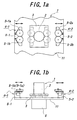
- FIGS. 1(a) and 1(b) illustrate a top view and a front view, respectively, of a ceramic shaped body-positioning system in accordance with one preferred embodiment of the present invention.
- a positioning system 1 for the ceramic shaped bodies according to the present invention comprise a centering table 3 for placing a ceramic shaped body 2, a plurality of (two, in this case) chucking units 4-1 and 4-2 which are provided on a base 11, and a drive unit 6 for moving the chucking units toward/away from the ceramic shaped body 2.
- Each of the chucking units 4-1 and 4-2 comprises a chucking body 5-1, 5-2 and two pairs of ceramic shaped body-pushing members 5-1a and 5-1b, 5-2a and 5-2b provided in the chucking bodies 5-1 and 5-2, respectively.
- a peripheral surface portion of each of the ceramic shaped body-pushing members 5-1a, 5-1b, 5-2a and 5-2b is made of an elastic material such as rubber.
- the chucking units 4-1 and 4-2 are moved toward and away from the ceramic shaped body 2 under control by the drive unit 6 provided on the base 11.
- the drive unit 6 is configured to move the chucking units 4-1 and 4-2 in the same direction, i.e. in an approaching direction or a departing direction, at the same speed.
- each of the chucking units 4-1 and 4-2 may have an individual drive unit to be able to independently control the movement.
- the positions and the speeds of each of the chucking units 4-1 and 4-2 can be accurately controlled, and even when the ceramic shaped body 2 such as the thin-walled ceramic honeycomb structural body is to be positioned, the ceramic shaped body 2 can be effectively prevented from causing cracks and breakages. Moreover, the ceramic shaped body 2 can be chucked with a sufficient force under fine control by the servomotor, so the positioning precision can be improved. Although a shock is given on the ceramic shaped body even in this case, the shock is remarkably reduced and far from destructive.
- the pairs of the ceramic shaped body-pushing members 5-1a and 5-1b, 5-2a and 5-2b are detachably mounted at given positions on the chucking bodies 5-1 and 5-2, respectively.
- the system for positioning the ceramic shaped bodies according to the present invention can be readily adapted to the cylindrical ceramic honeycomb structural bodies having different diameters or the odd-shaped ceramic shaped bodies by changing the mounting positions of the ceramic shaped body-pushing members 5-1a, 5-1b, 5-2a and 5-2b on the chucking bodies 5-1 and 5-2 without replacing the entire chucking units 4-1 and 4-2.
- the ceramic shaped body-pushing members 5-1a, 5-1b, 5-2a and 5-2b are mounted on the chucking bodies 5-1 and 5-2 in such a state that each of them can apply a force to the ceramic shaped body 2 in a different direction from the moving direction of the chucking unit 4-1, 4-2 when it contacts said ceramic shaped body.
- each of the ceramic shaped body-pushing members 5-1a, 5-1b, 5-2a and 5-2b is provided so that a tangent line of a contact point is not perpendicular to the moving direction of the chucking body 5-1, 5-2, whereby the ceramic shaped body-pushing body 5-1a, 5-1b, 5-2a, 5-2b can push the ceramic shaped body 2 not only in the moving direction of the chucking unit 4-1, 4-2, but also in a transversal direction to the moving direction.
- the system can simultaneously position the ceramic shaped body 2 in both of a moving direction of the chucking units 4-1 and 4-2 and the transversal direction even though the chucking units 4-1 and 4-2 move in uniaxial direction.
- the ceramic shaped body 2 after finishing the previous step e.g. a drying step is loaded at a given position on the centering table 3 by not-shown means for conveying.
- a drying step is loaded at a given position on the centering table 3 by not-shown means for conveying.
- the system with two chucking units 4-1 and 4-2 for one ceramic shaped body 2 is described, if there is a demand for continuously working a plurality of, for example, five, ceramic shaped bodies in the following step at one time such as a finish working step, the plurality of ceramic shaped bodies are loaded side by side on a not-shown table 3 having a larger shape than the centering table and the plurality of ceramic shaped bodies 2 can be simultaneously positioned by respectively provided pairs of the chucking units 4-1 and 4-2. It may be that a plurality of centering tables are employed, and ceramic shaped bodies 2 are individually placed thereon.
- the position of the ceramic shaped body 2 placed on the centering table 3 is roughly adjusted by a device for conveying the ceramic shaped body 2 from the previous step.
- the ceramic shaped body 2 is not exactly positioned on the centering table 3. Therefore, the positioning according to the present invention is necessary.
- the chucking units 4-1 and 4-2 are simultaneously moved toward the ceramic shaped body 2 by operating the drive unit 6 (servomotor).
- the chucking units 4-1 and 4-2 are moved to pre-memorized positions depending on the mounted positions of the ceramic shaped body-pushing members 5-1a, 5-1b, 5-2a and 5-2b, and then the operation of the drive unit 6 is controlled to move the ceramic shaped body 2 to a place where it is to be positioned.
- the ceramic shaped body 2 may be moved to that positioning place by the ceramic shaped body-pushing members 5-1a, 5-1b, 5-2a and 5-2b.
- the chucking units 4-1 and 4-2 are simultaneously moved away from the ceramic shaped body 2, and then the ceramic shaped body 2 already positioned on the centering table 3 is transferred to the next step by a not-shown conveying device.
- FIG. 2 illustrates the configuration of the chucking units 4-1 and 4-2 in accordance with one embodiment of the present invention, in which same or like elements as shown in FIG. 1 are given same numerals and their descriptions will be omitted.
- a plurality of holes 21 are provided in the chucking bodies 5-1 and 5-2 and shafts 22-1a, 22-1b, 22-2a and 22-2b are provided in the ceramic shaped body-pushing members 5-1a, 5-1b, 5-2a and 5-2b, respectively.
- the chucking bodies 5-1 and 5-2 have planar shapes provided with a plurality of holes 21 in a line.
- the pairs of the ceramic shaped body-pushing members 5-1a and 5-1b, 5-2a and 5-2b are mounted on the chucking bodies 5-1 and 5-2, respectively.
- the chucking units 4-1 and 4-2 shown in FIG. 2 can be used for positioning the ceramic shaped body 2 having an odd shape, and more effectively used for positioning the ceramic shaped body 2 having a symmetrical shape such as a cylindrical shape.
- the same chucking units 4-1 and 4-2 can be adapted for positioning the ceramic shaped bodies 2 having different diameters.
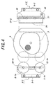
- FIGS. 3 and 4 illustrate the configurations of chucking units 4-1 and 4-2 in accordance with further embodiment of the present invention.
- same or like elements as shown in FIGS. 1 and 2 are also given same numerals and their description will be omitted.
- L-shaped planar attachments 31-1 and 31-2 provided with a plurality of holes are mounted on the chucking bodies 5-1 and 5-2 shown in FIG. 2, respectively, to make each of the chucking bodies 5-1 and 5-2 into a L-shaped planar form having a plurality of holes in a L-shaped line in the entirety. That is, each of the L-shaped planar attachments 31-1 and 31-2 is provided with a plurality of holes 32 linearly located in the same positions as those of the holes 21 provided in the chucking bodies 5-1 and 5-2 shown in FIG. 2 and a hole 33 located in the vertical portion.
- the holes 21, 32 and 33 are aligned in L-shape in each of the chucking bodies 5-1 and 5-2 in the entirety.
- one ceramic shaped body-pushing member 5-1b, 5-2b is inserted in appropriate one of the holes 21, 32 aligned in a line, and the other ceramic shaped body-pushing member 5-1a, 5-2b is inserted in the hole 33 on the vertical portion. This gives an effective positioning for the odd-shaped ceramic shaped body 2.
- one chucking unit 4-1 has the same configuration as that of the chucking unit 4-1 shown in FIG. 2, and the other chucking unit 4-2 is configured by mounting the L-shaped planar attachment 31-2 on the chucking unit 4-2 shown in FIG. 2 in a reverse manner of the embodiment shown in FIG. 3. That is, the L-shaped planar attachment 31-2 is mounted on the chucking body 5-2 so that a linear edge portion without the bent portion of the attachment 31-2 may face the ceramic shaped body 2. Further, a pad 34 is provided on an edge face of the attachment to be contacted with the ceramic shaped body 2. In the embodiment shown in FIG.
- the ceramic shaped body 2 can be more effectively positioned while the ceramic shaped body 2 contact the flat pad at the flat portion.
- the attachment 31-2 can be used for both of the embodiments shown in FIGS. 3 and 4.
- a placing orientation of the odd-shaped ceramic shaped body 2 on the centering table 3 may be variously chosen depending on the conveying means of the previous step, and the chucking units 4-1 and 4-2 having optimum configurations may be selected depending on the chosen orientation of the ceramic shaped body 2.
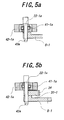
- FIGS. 5(a) and 5(b) illustrates such a configuration.
- the description will be made on the ceramic shaped body-pushing member 5-1a as an example, but it is to be understood that the other ceramic shaped body-pushing members 5-1b, 5-2a and 5-2b have the same configuration.
- FIG. 1 In the embodiment shown in FIG. 1
- the ceramic shaped body-pushing member 5-1a is mounted on the chucking body 5-1 by directly inserting a shaft 22-1a provided through the ceramic shaped body-pushing member 5-1a into one of the holes 21 provided in the chucking body 5-1.
- a pushing element 42-1a of which the peripheral surface is made of elastic body is installed around the shaft 22-1a via a bearing 41-1a to form the ceramic shaped body-pushing member 5-1a.
- FIG. 5(b) illustrates an embodiment where the attachment 31-1 is installed. The configuration of this embodiment is the same as the embodiment shown in FIG. 5(a) except that the shaft 22-1a also passes through the hole 32 of the attachment 31-1.
- the chucking units move only in the same linear directions.
- the chucking units may move in different directions.
- three chucking units may be arranged along a circle while being shaped by 120 degrees or four chucking units arranged along a circle while being shaped by 90 degrees.
- the system can also position the ceramic article in the same manner as mentioned above.
- the ceramic shaped body can be accurately positioned without causing deformations, cracks and breakages.
- the positions of the chucking units can be memorized, the adjustment of the chucking units are easily made according to the kinds of the ceramic shaped bodies, and the positioning precision is improved, so occurrences of improper cuttings can be reduced. Furthermore, with the attachment provided with a plurality of holes, the number of special jigs is reduced and the positioning system can be readily adapted to various kinds of the ceramic shaped bodies including odd-shaped one.
Landscapes
- Engineering & Computer Science (AREA)
- Mechanical Engineering (AREA)
- Devices For Post-Treatments, Processing, Supply, Discharge, And Other Processes (AREA)
- Press-Shaping Or Shaping Using Conveyers (AREA)
Abstract
Description
- The present invention relates to a ceramic shaped body-positioning system, which is used for accurately conveying the ceramic shaped bodies to the following step by adjusting positions of the ceramic shaped bodies.
- Heretofore, the following process is known as an example of a process for producing ceramic products such as ceramic honeycomb structural bodies. First, ceramic shaped bodies are obtained by molding a ceramic material and cut in a given length. Then, the cut ceramic shaped bodies are individually placed on cradles, and the cradles on which the ceramic shaped bodies are placed are moved on and along a conveyor path. After the movement, the ceramic shaped bodies are then dried in such a state that a given number of (for example, five) ceramic shaped bodies are aligned, and both end face positions of the dried ceramic shaped bodies are cut for finish working. Finally, the finish worked ceramic shaped bodies are fired to obtain ceramic products.
- In the aforementioned conventional process for producing the ceramic honeycomb structural bodies, when, for example, the ceramic shaped body is conveyed to a finishing step after drying, it is necessary to position the ceramic shaped body by correcting lateral and directional deviations of the ceramic shaped body on a table on which the ceramic shaped body is placed in order to accurately convey the ceramic shaped body to the subsequent finishing step. NGK Insulator, Ltd. discloses a technique for the above positioning in JP-A-61-226415, in which a plurality of actuators driven by air cylinders center the shaped bodies to a predetermined position on a conveyor belt in a simple and precise manner.
- In the aforementioned conventional positioning system for the ceramic shaped bodies, when a green ceramic honeycomb shaped body is to be positioned, a shock is applied to the ceramic honeycomb shaped body through contacting the actuator upon a peripheral face of the ceramic honeycomb shaped body. Even if such a shock acts upon the ceramic honeycomb shaped bodies, the conventional ceramic honeycomb shaped bodies are not deformed, cracked or broken since such ceramic honeycomb shaped bodies have a cell-wall thickness of about 150 µm and a cell density of about 400 cell/sq. in. and thus have high strengths. Therefore, final ceramic products can be obtained without any problems.
- However, thin-walled ceramic honeycomb shaped bodies having a cell-wall thickness of 120 µm or less and a cell density of about 400-1600 cell/sq. in., which are highly demanded these days, are much weaker than the conventional shaped bodies especially in the green state. Thus, when the thin-walled ceramic honeycomb shaped bodies are positioned with a conventional positioning system for the ceramic shaped bodies, the ceramic shaped body may be deformed, cracked or, in an extreme case, even broken with the shock caused by the actuators since it is difficult to reduce the speeds of the actuators at the time of gripping the ceramic honeycomb shaped body. On the contrary, if such a ceramic honeycomb shaped body is chucked with a weak force so as not to break it, another problem of a poor positioning accuracy occurs. The problem is more significant especially when the ceramic honeycomb shaped body having an odd-shaped (asymmetric) cross section is to be positioned.
- It is a conventional practice for overcoming the above problems that lengths of arms and gripping rollers are adjusted or replaced according to the kinds of products to modify a chucking unit. Especially for odd-shaped products, specially designed arms and rollers are required. However, such an adjustment or a replacement is time-consuming and causes a low productivity.
- It is, therefore, an object of the present invention to solve the above problems and to provide a ceramic shaped body-positioning system which can accurately position even thin-walled ceramic shaped bodies without causing deformations, cracks or breakages.
- The ceramic shaped body-positioning system according to the present invention is used for positioning the ceramic shaped body to accurately convey the ceramic shaped body to a next step, which comprises a centering table for placing the ceramic shaped body, a plurality of chucking units comprising a chucking body and a ceramic shaped body-pushing member provided in the chucking body, and a drive unit for moving the chucking units toward/away from the ceramic shaped body on the centering table, wherein the drive unit makes the plurality of chucking units simultaneously approach and push the ceramic shaped body on the centering table while controlling positions and speeds of the chucking units, thereby adjusting the positions of the ceramic shaped body on the centering table with giving substantially no destructive shock on the ceramic shaped body.
- In the aforementioned positioning system according to the present invention, the plurality of chucking unit simultaneously approach and push the ceramic shaped body to adjust the position of the ceramic shaped body on the centering table while controlling the positions and the speeds of the chucking units, therefore even if the positioning system is applied for the ceramic shaped bodies having low strength such as thin-walled ceramic honeycomb structural bodies, the ceramic shaped body can be accurately positioned without causing deformations, cracks and breakages.
- In a preferred embodiment of the present invention, it is preferable that the drive unit for moving the chucking unit comprises at least one servomotor, since the system can control the positions and the speeds of the chucking unit more accurately than the conventional system driven by air cylinders does. It is also preferable that the ceramic shaped body-pushing member is configured in a manner that it can be detachably mounted at any of given positions on the chucking body, since the system can be adapted to position ceramic shaped bodies having different shapes. Moreover, in this case, it is preferable that the chucking body is provided with a plurality of holes, a shaft are provided for the ceramic shaped body-pushing member, and the shaft is inserted into any of the hole to selectively set the ceramic shaped body-pushing member in the chucking body, since the ceramic shaped body-pushing member can be easily and detachably mounted at a given position on the chucking body. Furthermore, when the chucking body has a planar form and a plurality of holes are provided in the chucking body in a line, the present invention can be more suitably applied for, for example, the cylindrical ceramic shaped bodies having different diameters. When the chucking body has a L-shaped planar form and a plurality of holes are provided and aligned in the chucking body in a L-shape, the present invention can be applied for the odd-shaped ceramic shaped bodies having asymmetric, for example, pentagonal cross sections. Either of the above is preferable.
- For the better understanding of the present invention, reference is made to the accompanying drawings, in which:
- FIG. 1(a) is a top view of a system for positioning the ceramic shaped bodies in accordance with one preferred embodiment of the present invention;
- FIG. 1(b) is a front view of the system for positioning the ceramic shaped bodies in accordance with the above embodiment of the present invention;
- FIG. 2 illustrates the configuration of chucking units in accordance with the above embodiment of the present invention;
- FIG. 3 illustrates the configuration of chucking units in accordance with another embodiment of the present invention;
- FIG. 4 illustrates the configuration of chucking units in accordance with a further embodiment of the present invention;
- FIG. 5(a) illustrates the configuration in which the ceramic shaped body-pushing members is detachably mounted on the chucking body; and
- FIG. 5(b) shows another configuration in which the ceramic shaped body-pushing member is detachably mounted on the chucking body.
-
- Referring now to the drawings, FIGS. 1(a) and 1(b) illustrate a top view and a front view, respectively, of a ceramic shaped body-positioning system in accordance with one preferred embodiment of the present invention. In the embodiment shown in FIGS 1(a) and 1(b), a
positioning system 1 for the ceramic shaped bodies according to the present invention comprise a centering table 3 for placing a ceramicshaped body 2, a plurality of (two, in this case) chucking units 4-1 and 4-2 which are provided on abase 11, and adrive unit 6 for moving the chucking units toward/away from the ceramicshaped body 2. Each of the chucking units 4-1 and 4-2 comprises a chucking body 5-1, 5-2 and two pairs of ceramic shaped body-pushing members 5-1a and 5-1b, 5-2a and 5-2b provided in the chucking bodies 5-1 and 5-2, respectively. A peripheral surface portion of each of the ceramic shaped body-pushing members 5-1a, 5-1b, 5-2a and 5-2b is made of an elastic material such as rubber. - The chucking units 4-1 and 4-2 are moved toward and away from the ceramic
shaped body 2 under control by thedrive unit 6 provided on thebase 11. Although the detailed configuration of the servomotor is omitted here, a conventionally known configuration can be adapted. In this embodiment, thedrive unit 6 is configured to move the chucking units 4-1 and 4-2 in the same direction, i.e. in an approaching direction or a departing direction, at the same speed. Of course, each of the chucking units 4-1 and 4-2 may have an individual drive unit to be able to independently control the movement. By using a servomotor as thedrive unit 6, the positions and the speeds of each of the chucking units 4-1 and 4-2 can be accurately controlled, and even when the ceramic shapedbody 2 such as the thin-walled ceramic honeycomb structural body is to be positioned, the ceramicshaped body 2 can be effectively prevented from causing cracks and breakages. Moreover, the ceramicshaped body 2 can be chucked with a sufficient force under fine control by the servomotor, so the positioning precision can be improved. Although a shock is given on the ceramic shaped body even in this case, the shock is remarkably reduced and far from destructive. - In this embodiment, as detailed later, the pairs of the ceramic shaped body-pushing members 5-1a and 5-1b, 5-2a and 5-2b are detachably mounted at given positions on the chucking bodies 5-1 and 5-2, respectively. In this manner, as the ceramic shaped body-pushing members 5-1a, 5-1b, 5-2a and 5-2b are detachably mounted on the chucking bodies 5-1 and 5-2, the system for positioning the ceramic shaped bodies according to the present invention can be readily adapted to the cylindrical ceramic honeycomb structural bodies having different diameters or the odd-shaped ceramic shaped bodies by changing the mounting positions of the ceramic shaped body-pushing members 5-1a, 5-1b, 5-2a and 5-2b on the chucking bodies 5-1 and 5-2 without replacing the entire chucking units 4-1 and 4-2.
- Further, in this embodiment, the ceramic shaped body-pushing members 5-1a, 5-1b, 5-2a and 5-2b are mounted on the chucking bodies 5-1 and 5-2 in such a state that each of them can apply a force to the ceramic
shaped body 2 in a different direction from the moving direction of the chucking unit 4-1, 4-2 when it contacts said ceramic shaped body. More specifically, each of the ceramic shaped body-pushing members 5-1a, 5-1b, 5-2a and 5-2b is provided so that a tangent line of a contact point is not perpendicular to the moving direction of the chucking body 5-1, 5-2, whereby the ceramic shaped body-pushing body 5-1a, 5-1b, 5-2a, 5-2b can push the ceramic shapedbody 2 not only in the moving direction of the chucking unit 4-1, 4-2, but also in a transversal direction to the moving direction. In addition, by providing a plurality of (in this embodiment, two) of ceramic shaped body-pushing members on each of chucking bodies, the system can simultaneously position the ceramicshaped body 2 in both of a moving direction of the chucking units 4-1 and 4-2 and the transversal direction even though the chucking units 4-1 and 4-2 move in uniaxial direction. - In the
positioning system 1 for the ceramic shaped bodies shown in FIGS. 1(a) and 1(b), the ceramicshaped body 2 after finishing the previous step, e.g. a drying step is loaded at a given position on the centering table 3 by not-shown means for conveying. In the embodiment shown in FIGS. 1(a) and 1(b), although the system with two chucking units 4-1 and 4-2 for one ceramicshaped body 2 is described, if there is a demand for continuously working a plurality of, for example, five, ceramic shaped bodies in the following step at one time such as a finish working step, the plurality of ceramic shaped bodies are loaded side by side on a not-shown table 3 having a larger shape than the centering table and the plurality of ceramicshaped bodies 2 can be simultaneously positioned by respectively provided pairs of the chucking units 4-1 and 4-2. It may be that a plurality of centering tables are employed, and ceramicshaped bodies 2 are individually placed thereon. - The position of the ceramic shaped
body 2 placed on the centering table 3 is roughly adjusted by a device for conveying the ceramic shapedbody 2 from the previous step. However, the ceramicshaped body 2 is not exactly positioned on the centering table 3. Therefore, the positioning according to the present invention is necessary. In this embodiment, the chucking units 4-1 and 4-2 are simultaneously moved toward the ceramicshaped body 2 by operating the drive unit 6 (servomotor). On this occasion, the chucking units 4-1 and 4-2 are moved to pre-memorized positions depending on the mounted positions of the ceramic shaped body-pushing members 5-1a, 5-1b, 5-2a and 5-2b, and then the operation of thedrive unit 6 is controlled to move the ceramic shapedbody 2 to a place where it is to be positioned. In this way, even if the ceramicshaped body 2 is loaded at a place deviated from the positioning place, the ceramic shapedbody 2 may be moved to that positioning place by the ceramic shaped body-pushing members 5-1a, 5-1b, 5-2a and 5-2b. After positioning, the chucking units 4-1 and 4-2 are simultaneously moved away from the ceramic shapedbody 2, and then the ceramicshaped body 2 already positioned on the centering table 3 is transferred to the next step by a not-shown conveying device. - In the following, the configuration of other chucking units 4-1 and 4-2 will be described by way of example. FIG. 2 illustrates the configuration of the chucking units 4-1 and 4-2 in accordance with one embodiment of the present invention, in which same or like elements as shown in FIG. 1 are given same numerals and their descriptions will be omitted. In the embodiment shown in FIG. 2, a plurality of
holes 21 are provided in the chucking bodies 5-1 and 5-2 and shafts 22-1a, 22-1b, 22-2a and 22-2b are provided in the ceramic shaped body-pushing members 5-1a, 5-1b, 5-2a and 5-2b, respectively. In this embodiment, the chucking bodies 5-1 and 5-2 have planar shapes provided with a plurality ofholes 21 in a line. By inserting the shafts 22-1a, 22-1b, 22-2a and 22-2b into appropriate holes, respectively, the pairs of the ceramic shaped body-pushing members 5-1a and 5-1b, 5-2a and 5-2b are mounted on the chucking bodies 5-1 and 5-2, respectively. The chucking units 4-1 and 4-2 shown in FIG. 2 can be used for positioning the ceramic shapedbody 2 having an odd shape, and more effectively used for positioning the ceramic shapedbody 2 having a symmetrical shape such as a cylindrical shape. By changing mounting positions of the ceramic shaped body-pushing members 5-1a, 5-1b, 5-2a and 5-2b according to the diameter of the ceramicshaped body 2, the same chucking units 4-1 and 4-2 can be adapted for positioning the ceramic shapedbodies 2 having different diameters. - FIGS. 3 and 4 illustrate the configurations of chucking units 4-1 and 4-2 in accordance with further embodiment of the present invention. In these figures, same or like elements as shown in FIGS. 1 and 2 are also given same numerals and their description will be omitted.
- In the embodiment shown in FIG. 3, L-shaped planar attachments 31-1 and 31-2 provided with a plurality of holes are mounted on the chucking bodies 5-1 and 5-2 shown in FIG. 2, respectively, to make each of the chucking bodies 5-1 and 5-2 into a L-shaped planar form having a plurality of holes in a L-shaped line in the entirety. That is, each of the L-shaped planar attachments 31-1 and 31-2 is provided with a plurality of
holes 32 linearly located in the same positions as those of theholes 21 provided in the chucking bodies 5-1 and 5-2 shown in FIG. 2 and ahole 33 located in the vertical portion. By overlapping the holes of the attachments 31-1 and 31-2 with theholes 21 provided in the chucking bodies 5-1 and 5-2 shown in FIG. 2, theholes holes hole 33 on the vertical portion. This gives an effective positioning for the odd-shaped ceramic shapedbody 2. - In the embodiment shown in FIG. 4, one chucking unit 4-1 has the same configuration as that of the chucking unit 4-1 shown in FIG. 2, and the other chucking unit 4-2 is configured by mounting the L-shaped planar attachment 31-2 on the chucking unit 4-2 shown in FIG. 2 in a reverse manner of the embodiment shown in FIG. 3. That is, the L-shaped planar attachment 31-2 is mounted on the chucking body 5-2 so that a linear edge portion without the bent portion of the attachment 31-2 may face the ceramic shaped
body 2. Further, apad 34 is provided on an edge face of the attachment to be contacted with the ceramicshaped body 2. In the embodiment shown in FIG. 4 in which the odd-shaped ceramic shapedbody 2 has a flat portion, the ceramic shapedbody 2 can be more effectively positioned while the ceramic shapedbody 2 contact the flat pad at the flat portion. The attachment 31-2 can be used for both of the embodiments shown in FIGS. 3 and 4. A placing orientation of the odd-shaped ceramic shapedbody 2 on the centering table 3 may be variously chosen depending on the conveying means of the previous step, and the chucking units 4-1 and 4-2 having optimum configurations may be selected depending on the chosen orientation of the ceramicshaped body 2. - In the following, a configuration where the pairs of the ceramic shaped body-pushing members 5-1a and 5-1b, 5-2a and 5-2b are detachably mounted at given positions on the chucking bodies 5-1 and 5-2, respectively, will be described. Each of FIGS. 5(a) and 5(b) illustrates such a configuration. Hereinafter, the description will be made on the ceramic shaped body-pushing member 5-1a as an example, but it is to be understood that the other ceramic shaped body-pushing members 5-1b, 5-2a and 5-2b have the same configuration. In the embodiment shown in FIG. 5(a), the ceramic shaped body-pushing member 5-1a is mounted on the chucking body 5-1 by directly inserting a shaft 22-1a provided through the ceramic shaped body-pushing member 5-1a into one of the
holes 21 provided in the chucking body 5-1. In this embodiment, a pushing element 42-1a of which the peripheral surface is made of elastic body is installed around the shaft 22-1a via a bearing 41-1a to form the ceramic shaped body-pushing member 5-1a. Further, in this embodiment, when the shaft 22-1a is completely inserted through thehole 21, a spring member 43 is provided at a tip of the shaft 22-1a so that the spring member penetrates the shaft 22-1a and ahead portion 43a of the spring member 43 stick out from the shaft 22-1a below the chucking body 5-1. The spring member 43 can prevent the ceramic shaped body-pushing member 5-1a from coming off thehole 21. FIG. 5(b) illustrates an embodiment where the attachment 31-1 is installed. The configuration of this embodiment is the same as the embodiment shown in FIG. 5(a) except that the shaft 22-1a also passes through thehole 32 of the attachment 31-1. - In the above embodiments, the chucking units move only in the same linear directions. However, the chucking units may move in different directions. For example, three chucking units may be arranged along a circle while being shaped by 120 degrees or four chucking units arranged along a circle while being shaped by 90 degrees. In these cases, the system can also position the ceramic article in the same manner as mentioned above.
- As having clearly shown in the above description, according to the present invention, since a plurality of chucking units are simultaneously moved toward and push the ceramic shaped body on the centering table to adjust the position of the ceramic shaped body on the centering table while speeds of the chucking units upon chucking are controlled with the servomotor to absorb an impact on the ceramic shaped body, even if the positioning system is applied for the ceramic shaped bodies having low strength such as a thin-walled ceramic honeycomb structural body, the ceramic shaped body can be accurately positioned without causing deformations, cracks and breakages. In addition, since the positions of the chucking units can be memorized, the adjustment of the chucking units are easily made according to the kinds of the ceramic shaped bodies, and the positioning precision is improved, so occurrences of improper cuttings can be reduced. Furthermore, with the attachment provided with a plurality of holes, the number of special jigs is reduced and the positioning system can be readily adapted to various kinds of the ceramic shaped bodies including odd-shaped one.
Claims (8)
- A ceramic shaped body-positioning system, used for positioning the ceramic shaped body to convey the ceramic shaped body to a next step, said system comprising a centering table for placing the ceramic shaped body, a plurality of chucking units each comprising a chucking body and a ceramic shaped body-pushing member provided in the chucking body, and a drive unit for moving the chucking units toward/away from the ceramic shaped body on the centering table, wherein the drive unit makes the plurality of chucking units approach and push the ceramic shaped body on the centering table while controlling positions and speeds of the chucking units, thereby adjusting the position of the ceramic shaped body on the centering table.
- A ceramic shaped body-positioning system as claimed in Claim 1, wherein said drive unit comprise at least one servomotor.
- A ceramic shaped body-positioning system as claimed in Claim 1 or 2, wherein said ceramic shaped body-pushing member is detachably mounted at a given position on said chucking body.
- A ceramic shaped body-positioning system as claimed in Claim 3, wherein a plurality of holes are provided in said chucking body, a shaft is provided in said ceramic shaped body-pushing member, and said shaft is inserted in one of said holes to mount said ceramic shaped body-pushing member on said chucking body.
- A ceramic shaped body-positioning system as claimed in Claim 3 or 4, wherein said chucking body has a planar form and a plurality of holes are provided in said chucking body in a line.
- A ceramic shaped body-positioning system as claimed in Claim 3 or 4, wherein said chucking body has a L-shaped planar form and a plurality of holes are provided and aligned in said chucking body in L-shape.
- A ceramic shaped body-positioning system as claimed in any one of Claims 1-6, wherein said system is configured to simultaneously position said ceramic shaped body in both of a moving direction of said chucking units and a transversal direction by mounting said ceramic shaped body-pushing member in such a state that it can apply a force to the ceramic shaped body in a different direction from the moving direction of the chucking units when it contacts said ceramic shaped body.
- A ceramic shaped body-positioning system as claimed in Claim 7, wherein said system is configured to simultaneously position said ceramic shaped body in both of a moving direction of said chucking units and a transversal direction even if said chucking unit moves in uniaxial direction by providing a plurality of said ceramic shaped body-pushing members on one chucking body.
Applications Claiming Priority (2)
| Application Number | Priority Date | Filing Date | Title |
|---|---|---|---|
| JP2000246185 | 2000-08-15 | ||
| JP2000246185A JP2002059415A (en) | 2000-08-15 | 2000-08-15 | Ceramic molded body positioning system |
Publications (2)
| Publication Number | Publication Date |
|---|---|
| EP1180485A1 true EP1180485A1 (en) | 2002-02-20 |
| EP1180485B1 EP1180485B1 (en) | 2003-12-10 |
Family
ID=18736553
Family Applications (1)
| Application Number | Title | Priority Date | Filing Date |
|---|---|---|---|
| EP01306916A Expired - Lifetime EP1180485B1 (en) | 2000-08-15 | 2001-08-14 | A positioning device for ceramic articles |
Country Status (6)
| Country | Link |
|---|---|
| US (1) | US6659261B2 (en) |
| EP (1) | EP1180485B1 (en) |
| JP (1) | JP2002059415A (en) |
| CN (1) | CN1173867C (en) |
| DE (1) | DE60101431T2 (en) |
| ZA (1) | ZA200106410B (en) |
Cited By (1)
| Publication number | Priority date | Publication date | Assignee | Title |
|---|---|---|---|---|
| EP2537655A4 (en) * | 2010-12-07 | 2013-09-04 | Sumitomo Chemical Co | DEVICE FOR TRANSPORTING A STRUCTURAL NEST BODY, METHOD FOR SEALING A STRUCTURAL NICKEL BODY, AND METHOD FOR PRODUCING A STRUCTURAL BODY OF AN AREA OF WINDSCREEN |
Families Citing this family (13)
| Publication number | Priority date | Publication date | Assignee | Title |
|---|---|---|---|---|
| JP5753526B2 (en) * | 2012-10-25 | 2015-07-22 | 日本碍子株式会社 | Method for manufacturing ceramic honeycomb structure |
| WO2014152953A1 (en) * | 2013-03-14 | 2014-09-25 | Sealy Technology, Llc | Innerspring manufacturing and assembly system and components for selectable coil orientation, position adjustment and coil conveyance |
| US11076705B2 (en) | 2014-05-30 | 2021-08-03 | Sealy Technology, Llc | Spring core with integrated cushioning layer |
| CN105109997A (en) * | 2015-08-13 | 2015-12-02 | 广西北流市智诚陶瓷自动化科技有限公司 | Intermittent feeding mechanism for bowl blanks |
| DK3389450T3 (en) | 2015-12-17 | 2024-06-03 | Sealy Technology Llc | Coil-in-coil spring with variable load ratio and mattresses including one |
| MX2018008961A (en) | 2016-01-21 | 2019-05-06 | Sealy Technology Llc | Coil-in-coil springs with non-linear loading responses and mattresses including the same. |
| US10598242B2 (en) | 2016-05-20 | 2020-03-24 | Sealy Technology, Llc | Coil springs with non-linear loading responses and mattresses including the same |
| UA127787C2 (en) | 2017-10-31 | 2024-01-03 | Сілі Текнолоджи, Елелсі | Pocket coil spring assembly including flexible foam |
| CN110480798B (en) * | 2019-08-31 | 2024-07-16 | 湖南高峰陶瓷制造有限公司 | Ceramic blank forming automatic production line |
| CN113371430B (en) * | 2020-02-25 | 2024-06-25 | 富鼎电子科技(嘉善)有限公司 | Feeding device |
| CN111185341B (en) * | 2020-03-04 | 2024-02-13 | 苏州吉禄自动化科技有限公司 | Hole blocking drying equipment and hole blocking drying method |
| US12269138B2 (en) * | 2021-11-24 | 2025-04-08 | Corning Incorporated | Centering mechanisms for precision alignment of a component or ware |
| CN120773180B (en) * | 2025-07-18 | 2026-03-03 | 江苏宜翔陶瓷科技有限公司 | Ceramic body roll forming device of continuous rotation ejection of compact |
Citations (3)
| Publication number | Priority date | Publication date | Assignee | Title |
|---|---|---|---|---|
| DE2945807A1 (en) * | 1978-11-13 | 1980-05-22 | Walter Sticht | PRODUCTION PLANT FOR COMPONENTS TO BE PRODUCED IN TWO OR SEVERAL STEPS |
| JPS61226415A (en) | 1985-03-29 | 1986-10-08 | Ngk Insulators Ltd | Position adjuster for conveyed work |
| WO1998025841A1 (en) * | 1996-12-13 | 1998-06-18 | General Labels And Labelling (Singapore) Private Limited | Method for pre-determinably positioning and orientating an article or a series of similar articles being carried on a moving conveyor and apparatus therefor |
Family Cites Families (2)
| Publication number | Priority date | Publication date | Assignee | Title |
|---|---|---|---|---|
| US2614681A (en) * | 1949-08-06 | 1952-10-21 | Meyer Geo J Mfg Co | Article-orienting mechanism for labeling machines |
| US4257151A (en) * | 1979-03-23 | 1981-03-24 | The Coca-Cola Company | Inspection station for beverage containers |
-
2000
- 2000-08-15 JP JP2000246185A patent/JP2002059415A/en active Pending
-
2001
- 2001-08-01 US US09/919,593 patent/US6659261B2/en not_active Expired - Lifetime
- 2001-08-03 ZA ZA200106410A patent/ZA200106410B/en unknown
- 2001-08-14 DE DE60101431T patent/DE60101431T2/en not_active Expired - Lifetime
- 2001-08-14 EP EP01306916A patent/EP1180485B1/en not_active Expired - Lifetime
- 2001-08-15 CN CNB011254203A patent/CN1173867C/en not_active Expired - Lifetime
Patent Citations (5)
| Publication number | Priority date | Publication date | Assignee | Title |
|---|---|---|---|---|
| DE2945807A1 (en) * | 1978-11-13 | 1980-05-22 | Walter Sticht | PRODUCTION PLANT FOR COMPONENTS TO BE PRODUCED IN TWO OR SEVERAL STEPS |
| US4502585A (en) * | 1978-11-13 | 1985-03-05 | Walter Sticht | Workpiece carrier locating and clamping mechanism for assembly line arrangement |
| JPS61226415A (en) | 1985-03-29 | 1986-10-08 | Ngk Insulators Ltd | Position adjuster for conveyed work |
| US4741429A (en) * | 1985-03-29 | 1988-05-03 | Ngk Insulators, Ltd. | Centering apparatus for ceramic articles and the like |
| WO1998025841A1 (en) * | 1996-12-13 | 1998-06-18 | General Labels And Labelling (Singapore) Private Limited | Method for pre-determinably positioning and orientating an article or a series of similar articles being carried on a moving conveyor and apparatus therefor |
Cited By (2)
| Publication number | Priority date | Publication date | Assignee | Title |
|---|---|---|---|---|
| EP2537655A4 (en) * | 2010-12-07 | 2013-09-04 | Sumitomo Chemical Co | DEVICE FOR TRANSPORTING A STRUCTURAL NEST BODY, METHOD FOR SEALING A STRUCTURAL NICKEL BODY, AND METHOD FOR PRODUCING A STRUCTURAL BODY OF AN AREA OF WINDSCREEN |
| US8863685B2 (en) | 2010-12-07 | 2014-10-21 | Sumitomo Chemical Company, Limited | Device for conveying honeycomb structural body, method for sealing honeycomb structural body, and method for producing honeycomb structural body |
Also Published As
| Publication number | Publication date |
|---|---|
| EP1180485B1 (en) | 2003-12-10 |
| ZA200106410B (en) | 2002-02-11 |
| JP2002059415A (en) | 2002-02-26 |
| US6659261B2 (en) | 2003-12-09 |
| DE60101431T2 (en) | 2004-12-02 |
| US20020043444A1 (en) | 2002-04-18 |
| CN1338420A (en) | 2002-03-06 |
| DE60101431D1 (en) | 2004-01-22 |
| CN1173867C (en) | 2004-11-03 |
Similar Documents
| Publication | Publication Date | Title |
|---|---|---|
| EP1180485B1 (en) | A positioning device for ceramic articles | |
| US7469473B2 (en) | Assembly line vehicle body positioning | |
| EP0020982B1 (en) | A method and apparatus for orienting a wafer in a desired position at a work station | |
| US5348142A (en) | Adjustable pallet | |
| JP4789362B2 (en) | Substrate holding device | |
| US20030015001A1 (en) | Method of setting a machine for machining a sheet of glass, and machine configurable thereby | |
| CN114929433B (en) | Handling device | |
| JP4995977B2 (en) | Substrate holding device | |
| EP1118592A1 (en) | Unit for notching a sheet of laminated glass | |
| JPS6325237A (en) | Device for giving local work pressure on glass plate in production line of automobile glass plate | |
| US6419075B1 (en) | Device for aligning glass sheets on a roller conveyor of a glass annealing lehr | |
| CN111225771A (en) | Method and manipulator for orienting two workpieces for constructing a joint connection | |
| CN101842889B (en) | Device for supporting workpiece | |
| CN219359285U (en) | Machining clamp | |
| JP2002346868A (en) | Cylinder block positioning device | |
| CN111963577B (en) | Bearing unit assembling method and assembling equipment | |
| CN219358753U (en) | Limited moving clamp | |
| JP3827402B2 (en) | Hydrodynamic bearing groove forming device | |
| JP2002346967A (en) | Cylinder block holding device | |
| KR102880277B1 (en) | Bushing manufacturing device and bushing manufacturing method | |
| JP7287338B2 (en) | Positioning device and positioning method | |
| KR970003485B1 (en) | Machine for grinding edges | |
| JPH09248744A (en) | Workpiece processing method and device | |
| JPS5930612Y2 (en) | Shaft insertion device | |
| CN120080309A (en) | A valve seat handling manipulator and valve seat feeding equipment |
Legal Events
| Date | Code | Title | Description |
|---|---|---|---|
| PUAI | Public reference made under article 153(3) epc to a published international application that has entered the european phase |
Free format text: ORIGINAL CODE: 0009012 |
|
| AK | Designated contracting states |
Kind code of ref document: A1 Designated state(s): AT BE CH CY DE DK ES FI FR GB GR IE IT LI LU MC NL PT SE TR Kind code of ref document: A1 Designated state(s): BE DE |
|
| AX | Request for extension of the european patent |
Free format text: AL;LT;LV;MK;RO;SI |
|
| 17P | Request for examination filed |
Effective date: 20020521 |
|
| AKX | Designation fees paid |
Free format text: BE DE |
|
| 17Q | First examination report despatched |
Effective date: 20021015 |
|
| GRAH | Despatch of communication of intention to grant a patent |
Free format text: ORIGINAL CODE: EPIDOS IGRA |
|
| GRAS | Grant fee paid |
Free format text: ORIGINAL CODE: EPIDOSNIGR3 |
|
| GRAA | (expected) grant |
Free format text: ORIGINAL CODE: 0009210 |
|
| AK | Designated contracting states |
Kind code of ref document: B1 Designated state(s): BE DE |
|
| REG | Reference to a national code |
Ref country code: IE Ref legal event code: FG4D |
|
| REF | Corresponds to: |
Ref document number: 60101431 Country of ref document: DE Date of ref document: 20040122 Kind code of ref document: P |
|
| PLBE | No opposition filed within time limit |
Free format text: ORIGINAL CODE: 0009261 |
|
| STAA | Information on the status of an ep patent application or granted ep patent |
Free format text: STATUS: NO OPPOSITION FILED WITHIN TIME LIMIT |
|
| 26N | No opposition filed |
Effective date: 20040913 |
|
| REG | Reference to a national code |
Ref country code: IE Ref legal event code: MM4A |
|
| PGFP | Annual fee paid to national office [announced via postgrant information from national office to epo] |
Ref country code: BE Payment date: 20050831 Year of fee payment: 5 |
|
| PG25 | Lapsed in a contracting state [announced via postgrant information from national office to epo] |
Ref country code: BE Free format text: LAPSE BECAUSE OF NON-PAYMENT OF DUE FEES Effective date: 20060831 |
|
| BERE | Be: lapsed |
Owner name: *NGK INSULATORS LTD Effective date: 20060831 |
|
| PGFP | Annual fee paid to national office [announced via postgrant information from national office to epo] |
Ref country code: DE Payment date: 20200804 Year of fee payment: 20 |
|
| REG | Reference to a national code |
Ref country code: DE Ref legal event code: R071 Ref document number: 60101431 Country of ref document: DE |