EP1179871A2 - Electrochemical lithium ion secondary cell having multiplate electrodes with differing discharge rate regions - Google Patents
Electrochemical lithium ion secondary cell having multiplate electrodes with differing discharge rate regions Download PDFInfo
- Publication number
- EP1179871A2 EP1179871A2 EP01306658A EP01306658A EP1179871A2 EP 1179871 A2 EP1179871 A2 EP 1179871A2 EP 01306658 A EP01306658 A EP 01306658A EP 01306658 A EP01306658 A EP 01306658A EP 1179871 A2 EP1179871 A2 EP 1179871A2
- Authority
- EP
- European Patent Office
- Prior art keywords
- electrode
- cathode
- electrochemical cell
- cell according
- anode
- Prior art date
- Legal status (The legal status is an assumption and is not a legal conclusion. Google has not performed a legal analysis and makes no representation as to the accuracy of the status listed.)
- Withdrawn
Links
Images
Classifications
-
- H—ELECTRICITY
- H01—ELECTRIC ELEMENTS
- H01M—PROCESSES OR MEANS, e.g. BATTERIES, FOR THE DIRECT CONVERSION OF CHEMICAL ENERGY INTO ELECTRICAL ENERGY
- H01M10/00—Secondary cells; Manufacture thereof
- H01M10/04—Construction or manufacture in general
- H01M10/045—Cells or batteries with folded plate-like electrodes
-
- H—ELECTRICITY
- H01—ELECTRIC ELEMENTS
- H01M—PROCESSES OR MEANS, e.g. BATTERIES, FOR THE DIRECT CONVERSION OF CHEMICAL ENERGY INTO ELECTRICAL ENERGY
- H01M10/00—Secondary cells; Manufacture thereof
- H01M10/04—Construction or manufacture in general
- H01M10/0413—Large-sized flat cells or batteries for motive or stationary systems with plate-like electrodes
-
- H—ELECTRICITY
- H01—ELECTRIC ELEMENTS
- H01M—PROCESSES OR MEANS, e.g. BATTERIES, FOR THE DIRECT CONVERSION OF CHEMICAL ENERGY INTO ELECTRICAL ENERGY
- H01M10/00—Secondary cells; Manufacture thereof
- H01M10/04—Construction or manufacture in general
- H01M10/0445—Multimode batteries, e.g. containing auxiliary cells or electrodes switchable in parallel or series connections
-
- H—ELECTRICITY
- H01—ELECTRIC ELEMENTS
- H01M—PROCESSES OR MEANS, e.g. BATTERIES, FOR THE DIRECT CONVERSION OF CHEMICAL ENERGY INTO ELECTRICAL ENERGY
- H01M10/00—Secondary cells; Manufacture thereof
- H01M10/05—Accumulators with non-aqueous electrolyte
- H01M10/052—Li-accumulators
- H01M10/0525—Rocking-chair batteries, i.e. batteries with lithium insertion or intercalation in both electrodes; Lithium-ion batteries
-
- H—ELECTRICITY
- H01—ELECTRIC ELEMENTS
- H01M—PROCESSES OR MEANS, e.g. BATTERIES, FOR THE DIRECT CONVERSION OF CHEMICAL ENERGY INTO ELECTRICAL ENERGY
- H01M10/00—Secondary cells; Manufacture thereof
- H01M10/05—Accumulators with non-aqueous electrolyte
- H01M10/058—Construction or manufacture
- H01M10/0583—Construction or manufacture of accumulators with folded construction elements except wound ones, i.e. folded positive or negative electrodes or separators, e.g. with "Z"-shaped electrodes or separators
-
- H—ELECTRICITY
- H01—ELECTRIC ELEMENTS
- H01M—PROCESSES OR MEANS, e.g. BATTERIES, FOR THE DIRECT CONVERSION OF CHEMICAL ENERGY INTO ELECTRICAL ENERGY
- H01M4/00—Electrodes
- H01M4/02—Electrodes composed of, or comprising, active material
- H01M4/13—Electrodes for accumulators with non-aqueous electrolyte, e.g. for lithium-accumulators; Processes of manufacture thereof
- H01M4/131—Electrodes based on mixed oxides or hydroxides, or on mixtures of oxides or hydroxides, e.g. LiCoOx
-
- H—ELECTRICITY
- H01—ELECTRIC ELEMENTS
- H01M—PROCESSES OR MEANS, e.g. BATTERIES, FOR THE DIRECT CONVERSION OF CHEMICAL ENERGY INTO ELECTRICAL ENERGY
- H01M4/00—Electrodes
- H01M4/02—Electrodes composed of, or comprising, active material
- H01M4/13—Electrodes for accumulators with non-aqueous electrolyte, e.g. for lithium-accumulators; Processes of manufacture thereof
- H01M4/133—Electrodes based on carbonaceous material, e.g. graphite-intercalation compounds or CFx
-
- H—ELECTRICITY
- H01—ELECTRIC ELEMENTS
- H01M—PROCESSES OR MEANS, e.g. BATTERIES, FOR THE DIRECT CONVERSION OF CHEMICAL ENERGY INTO ELECTRICAL ENERGY
- H01M6/00—Primary cells; Manufacture thereof
- H01M6/04—Cells with aqueous electrolyte
- H01M6/06—Dry cells, i.e. cells wherein the electrolyte is rendered non-fluid
- H01M6/10—Dry cells, i.e. cells wherein the electrolyte is rendered non-fluid with wound or folded electrodes
- H01M6/103—Cells with electrode of only one polarity being folded or wound
-
- H—ELECTRICITY
- H01—ELECTRIC ELEMENTS
- H01M—PROCESSES OR MEANS, e.g. BATTERIES, FOR THE DIRECT CONVERSION OF CHEMICAL ENERGY INTO ELECTRICAL ENERGY
- H01M16/00—Structural combinations of different types of electrochemical generators
-
- Y—GENERAL TAGGING OF NEW TECHNOLOGICAL DEVELOPMENTS; GENERAL TAGGING OF CROSS-SECTIONAL TECHNOLOGIES SPANNING OVER SEVERAL SECTIONS OF THE IPC; TECHNICAL SUBJECTS COVERED BY FORMER USPC CROSS-REFERENCE ART COLLECTIONS [XRACs] AND DIGESTS
- Y10—TECHNICAL SUBJECTS COVERED BY FORMER USPC
- Y10T—TECHNICAL SUBJECTS COVERED BY FORMER US CLASSIFICATION
- Y10T29/00—Metal working
- Y10T29/49—Method of mechanical manufacture
- Y10T29/49002—Electrical device making
- Y10T29/49108—Electric battery cell making
Definitions
- the present invention generally relates to the conversion of chemical energy to electrical energy. More particularly, the present invention relates to a secondary electrochemical cell dischargeable under both a constant discharge rate and a pulse discharge rate. Cardiac defibrillators present both electrical power requirements.
- the constant discharge rate portion of the secondary cell of the present invention preferably includes a high mass, low surface area lithium-retention cathode structure associated with a carbonaceous anode electrode in a side-by-side prismatic configuration.
- the pulse discharge rate portion of the secondary cell of the present invention referred to hereinafter as the high rate region, preferably includes a high surface area lithium-retention cathode associated with a carbonaceous anode in a side-by-side prismatic configuration.
- the same anode structure is electrically associated with both the medium rate lithium-retention cathode region and the high rate lithium-retention cathode region housed within the same hermetically sealed casing. This structure defines what is meant by a medium rate region and a high rate region contained within the same secondary electrochemical cell.
- cardiac defibrillator cells have been built using a multiplate electrode design.
- the cell designer must decide between providing additional electrochemically active components for increased mass and energy density or providing increased surface area for greater power density. Because of the wide disparity in the energy/power requirements placed upon a cardiac defibrillator cell or battery, that being intermittent low rate and high rate operation, a compromise is often decided upon.
- any design attempt to balance the energy/power requirements placed upon the cell or battery by the defibrillator device must not consequently produce unwanted self-discharge reactions. This compromise can provide for inefficiency and can decrease the overall gravimetric and volumetric energy density of the cell.
- the electrodes within a cell should have as much mass and as little surface area as possible. At the expense of power density, this provides for increased energy density while the low electrode surface area minimizes undesirable self-discharge reactions. Conversely, when larger electrical discharge currents are required, electrode surface area and power density are maximized at the expense of energy density and self-discharge rate.
- the secondary cell of the present invention having an electrode assembly with differing discharge rate portions fulfills this need.
- the present secondary cell comprises regions containing a low interelectrode surface area in a side-by-side, prismatic configuration, preferred for routine monitoring by a device, for example a cardiac defibrillator, and regions containing a high interelectrode surface area in a side-by-side, prismatic configuration for use when high rate electrical pulse charging of capacitors is required with minimal polarization. It is believed that the present secondary electrochemical cell having electrodes with differing discharge rate regions represents a pioneering advancement wherein a medium discharge rate region and a high discharge rate region are provided within the same case for the purpose of having the cell supply at least two different electrical energy requirements.
- the present invention provides an improved multiplate electrode design for an electrochemical lithium ion secondary cell dischargeable to provide background current intermittently interrupted or supplemented by current pulse discharge.
- the disclosed secondary cell is of a case-negative design in which the carbonaceous anode assembly is in electrical contact with the case.
- Two positive terminal pins are respectively connected to two independent lithium-retention cathode regions.
- One lithium-retention cathode region has a relatively low surface area and high density for providing low electrical current on the order of microamperes to milliamperes and the other lithium-retention cathode region has a relatively high surface area for providing high electrical current on the order of several hundred milliamperes to amperes.
- the medium rate, constant discharge region of the present secondary cell comprises a lithium-retention cathode structure of one or more cathode plates flanked on either side by a carbonaceous anode.
- the lithium-retention cathode material which preferably comprises an air stable lithiated compound, suitable conductive additive(s) and a binder, may be in a dry powder form and is pressed onto a conductive metal screen or foil.
- the carbonaceous anode preferably consists of carbon fibers, mesocarbon microbeads, graphitic carbon, non-graphitic carbon, petroleum coke, and other types of carbon that are also pressed onto a conductive metal screen or foil.
- a metallic lead connects the medium rate cathode region to a feedthrough terminal pin in the battery header which is insulated from the battery case by a glass-to-metal seal.
- the anode is either connected to the case resulting in a case-negative configuration or to another feedthrough pin also located in the header of the battery.
- a separator prevents short circuiting between the couple.
- the high rate, pulse discharge region of the present secondary cell comprises a lithium-retention cathode structure of one or more cathode plates flanked on either side by the same anode that is coupled to the medium rate region.
- the interelectrode surface area of the high rate region is greater than that of the medium rate region to deliver high current pulses during device activation.
- the medium rate region contributes greater than 10% of the total energy density provided by the cell while having less than 50% of the total cathode surface area. Still more preferably, the medium rate region contributes greater than 10% of the total energy density provided by the cell while having less than 30% of the total cathode surface area.
- the present invention offers the advantage of having both a medium rate, constant discharge or constant drain region and a high rate, pulse discharge region provided within the same secondary electrochemical cell.
- the electrochemical couple used for both the medium rate region and the high rate region is, for example, a carbon/lithiated oxide couple such as a carbon/LiCoO 2 couple.
- both discharge region couples need not necessarily be identical.
- Secondary electrochemical cells according to the present invention having medium rate and high rate discharge regions can be constructed and designed to meet the drain rate and current discharge requirements of a particular application.
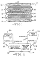
- Figs. 1 and 2 show a secondary electrochemical cell 10 with multiplate electrodes constructed according to the present invention having both a medium rate region 12 and a high rate region 14 hermetically sealed within a metallic, prismatic casing 16.
- the medium rate region 12 preferably provides a relatively constant discharge current and the high rate region 14 preferably provides a high current pulse discharge power source. Both electrode regions are activated with the same electrolyte solution.
- the present secondary cell comprises two positive terminal leads 18, 20 and a common negative terminal lead 22.
- the medium rate region and the high rate region have separate and distinct positive terminals and the same negative terminal, i.e., the prismatic casing 16.
- Two different loads are applied to this battery.
- a constant resistance load 24 is connected to the positive terminal 18 and the negative terminal 20, i.e., the casing 16, and a constant current pulse "load" 26 is connected to the positive terminal 20 and the casing 16.
- the housing 16 is vacuum filled with a nonaqueous electrolyte common to both the medium rate region 12 and the high rate region 14.
- a device providing both a constant resistance load and a constant current pulse "load" is, for example, an implantable medical device such as a cardiac defibrillator.
- the carbonaceous active material for the anode electrode of the medium rate region and the high rate region of a secondary electrochemical cell with multiplate electrodes is any of the various forms of carbon (e.g., coke, graphite, acetylene black, carbon black, etc.) which are capable of reversibly retaining the lithium species.
- Graphite is preferred due to its relatively high lithium-retention capacity.
- Carbon fibers are particularly advantageous because they have excellent mechanical properties which permit them to be fabricated into rigid electrodes that are capable of withstanding degradation during repeated charge-discharge cycling. Moreover, their high surface area allows rapid charge/discharge rates.
- the carbon may be contacted to a conductive substrate such as by pressing, bonding and the like.
- a preferred carbonaceous material for the anode of the present secondary electrochemical cell is described in U.S. Patent No. 5,443,928 to Takeuchi et al., which is assigned to the assignee of the present invention and incorporated herein by reference.
- a typical anode electrode is fabricated by mixing about 90 to 99 weight percent graphite with 1 to 10 weight percent of a fluoro-resin binder. This mixture is rolled onto a current collector such as nickel, stainless steel, or copper foil or screen.
- the graphite electrode can be lithiated electrochemically using a lithium electrode, chemically, or via the cathode.
- the Li x C 6 electrode can have an x range between 0.1 and 1.0.
- the anode for the medium rate region 12 and the high rate region 14 is a sheet 28 of the carbonaceous mixture, pressed or rolled on a metallic anode current collector, i.e., preferably comprising copper.
- the anode has an extended tab or lead of a metallic material, i.e., preferably nickel, integrally formed therewith, such as by welding.
- the lead is contacted by a weld to the conductive metal casing 16 serving as the negative terminal 20 in a case-negative configuration for both regions 12, 14.
- the casing 16 is preferably a prismatic housing that may comprise materials such as stainless steel, mild steel, nickel-plated mild steel, titanium or aluminum, but not limited thereto, so long as the metallic material is compatible for use with the other components of the cell.
- the lithium-retention cathode material for both the medium rate and high rate regions may comprise a lithiated material that is stable in air and readily handled.
- air-stable lithiated cathode materials include oxides, sulfides, selenides, and tellurides of such metals as vanadium, titanium, chromium, copper, molybdenum, niobium, iron, nickel, cobalt and manganese.
- the more preferred oxides include LiNiO 2 , LiMn 2 O 4 , LiCoO 2 , LiCo 0.92 Sn 0.08 O 2 and LiCo 1-x Ni x O 2 .
- the cathode active material may be in a dry powder form pressed onto a conductive metal screen.
- Aluminum is a suitable material for the cathode current collector.
- the cathode active material in a finely divided form is mixed with conductive diluents and a binder material and then pressed onto the current collector screen.
- the binder material is preferably a thermoplastic polymeric binder material.
- thermoplastic polymeric binder material is used in its broad sense and any polymeric material which is inert in the cell and which passes through a thermoplastic state, whether or not it finally sets or cures, is included within the term "thermoplastic polymer".
- Representative materials include polyethylene, polypropylene and fluoropolymers such as fluorinated ethylene and fluorinated propylene, polyvinylidene fluoride (PVDF) and polytetrafluoroethylene (PTFE), PVDF being most preferred. Natural rubbers are also useful as the binder material with the present invention.
- Suitable discharge promoter diluents include graphite powder, acetylene black powder and carbon black powder. Metallic powders such as aluminum and stainless steel are also useful as conductive diluents.
- about 80% to about 98%, by weight, of the lithium-retention cathode active material is mixed with about 1% to about 5% of the conductive diluents and about 1% to about 5% of the binder material. In some cases, no binder material or electronic conductor material is required to provide a similarly suitable cathode body.
- the cathode structure for the medium rate region may also be prepared by rolling, spreading or pressing a mixture of the materials mentioned above onto a suitable current collector.
- the cathode structure for the medium rate region 12, prepared as described above, is preferably in the form of one or more cathode plates 30 operatively associated with the previously described anode sheet 28.
- the cathode plates 30 have a relatively low surface area and high density.
- this electrode configuration provides low electrical current on the order of about 1 microampere to about 100 milliamperes corresponding to a C-Rate of about C/1,400,000 to about C/14.
- at least one cathode plate 30 having a thickness of about 0.001 inches to about 0.020 inches is flanked on either side by oppositely positioned surfaces of the anode 28 prepared as described above.
- the high rate region 14 of the present secondary cell comprises cathode plates 32 formed from a paste of lithium-retention cathode material, including binder and conductive additives, calendared into a free-standing structure that is subsequently dried and cut to shape.
- the shaped cathode structure having a thickness of about 0.0005 inches to about 0.010 inches is then pressed onto at least one side, and preferably both sides, of a current collector screen of a suitable material, such as aluminum, to provide the cathode structure in the form of plates 32.
- at least one cathode plate 32 is flanked on either side by oppositely positioned surfaces of the carbonaceous anode 28 not facing the cathode plates 30 of the medium rate section 12.
- this electrode configuration provides electrical current on the order of about 0.14 amps to about 14 amps corresponding to a C-Rate of about C/10 to about C/0.1 for the high rate region.
- a process for making cathode structures useful in the high rate region of the present multiplate electrode secondary cell is described in U.S. Patent No. 5,435,874 to Takeuchi et al., which is assigned to the assignee of the present invention and incorporated herein by reference.
- An alternate preparation technique is to cast a slurry of the lithium-retention cathode material onto a surface-treated metal foil followed by drying and calendaring.
- the lead 18 for the cathode plates 30 of the medium rate region 12 and the lead 20 for the cathode plates 32 of the high rate region 14 are insulated from the casing 16 by respective glass-to-metal seal/terminal lead feedthroughs.
- the glass used is of a corrosion resistant type having from between about 0% to about 50% by weight silicon such as CABAL 12, TA 23, CORNING 9013, FUSITE 425 or FUSITE 435.
- the positive terminal leads 18, 20 preferably comprise molybdenum although aluminum, nickel alloy, or stainless steel can also be used.
- Either or both of the lithium-retention cathode plates 30, 32 and the carbonaceous anode sheet 28 for both the medium rate and high rate regions may be sealed in their own separator envelopes (not shown for clarity) to prevent direct physical contact between them.
- the separator is of an electrically insulative material to prevent an internal electrical short circuit between the active materials, and the separator material also is chemically unreactive with the anode and cathode active materials and both chemically unreactive with and insoluble in the electrolyte.
- the separator material has a degree of porosity sufficient to allow flow therethrough of the electrolyte during the electrochemical reaction of the cell.
- Illustrative separator materials include woven and non-woven fabrics of polyolefinic fibers including polypropylene and polyethylene or fluoropolymeric fibers including polyvinylidine fluoride, polyethylenetetrafluoroethylene, and polyethylenechlorotrifluoroethylene laminated or superposed with a polyolefinic or fluoropolymeric microporous film, non-woven glass, glass fiber materials and, ceramic materials.
- Suitable microporous films include a polytetrafluoroethylene membrane commercially available under the designation ZITEX (Chemplast Inc.), a polypropylene membrane commercially available under the designation CELGARD (Celanese Plastic Company, Inc.) and a membrane commercially available under the designation DEXIGLAS (C.H. Dexter, Div., Dexter Corp.).
- the multiplate secondary electrochemical cell of the present invention further includes a nonaqueous, ionically conductive electrolyte which serves as a medium for migration of ions between the anode and the cathode structures during the electrochemical reactions of the cell.
- the electrochemical reaction at both the medium rate and high rate regions involves conversion of ions in atomic or molecular forms which migrate from the anode to the cathode during discharging of the cell and from the cathode back to the anode during charging of the cell.
- nonaqueous electrolytes suitable for the present invention exhibit those physical properties necessary for ionic transport namely, low viscosity, low surface tension and wettability.
- Suitable nonaqueous electrolytes are comprised of an inorganic salt dissolved in a nonaqueous solvent and more preferably an alkali metal salt dissolved in a mixture of aprotic organic solvents comprising a low viscosity solvent including organic esters, ethers and dialkyl carbonates, and mixtures thereof, and a high permittivity solvent including cyclic carbonates, cyclic esters and cyclic amides, and mixtures thereof.
- Suitable nonaqueous low viscosity solvents include tetrahydrofuran (THF), methyl acetate (MA), diglyme, triglyme, tetraglyme, dimethyl carbonate (DMC), diethyl carbonate (DEC), dipropyl carbonate (DPC), methyl ethyl carbonate (MEC), methyl propyl carbonate (MPC), ethyl propyl carbonate (EPC), 1,2-dimethoxyethane (DME), and others.
- THF tetrahydrofuran
- MA methyl acetate
- DMC diethyl carbonate
- DPC dipropyl carbonate
- MEC methyl ethyl carbonate
- MEC methyl propyl carbonate
- EPC ethyl propyl carbonate
- DME 1,2-dimethoxyethane
- Preferred high permittivity solvents include propylene carbonate (PC), ethylene carbonate (EC), butylene carbonate (BC), acetonitrile, dimethyl sulfoxide, dimethyl formamide, dimethyl acatamide, ⁇ -butyrolactone (GBL) and N-methylpyrrolidinone (NMP) and others.
- PC propylene carbonate
- EC ethylene carbonate
- BC butylene carbonate
- acetonitrile dimethyl sulfoxide
- dimethyl formamide dimethyl acatamide
- GBL ⁇ -butyrolactone
- NMP N-methylpyrrolidinone
- Suitable salt concentrations typically range between about 0.8 to 1.5 molar, and a preferred electrolyte for a rechargeable lithium ion cell according to the present invention includes LiAsF 6 or LiPF 6 dissolved in an equilibrated mixture of ethyl methyl carbonate, dimethyl carbonate, diethyl carbonate and ethylene carbonate.
- the rechargeable cell of the present invention is initially in a discharged state and lithium contained within the cathode is intercalated into the anode by applying an externally generated electrical potential to charge the cell.
- the applied electrical potential serves to draw the alkali metal ions from the cathode material, through the electrolyte and into the carbonaceous anode to saturate the carbonaceous material comprising the anode.
- the cell is then provided with an electrical potential and is discharged in a normal manner.
- the casing header comprises a metallic lid (not shown) having a sufficient number of openings to accommodate the glass-to-metal seal/terminal lead feedthroughs for the cathode plates 30, 32 of the medium and high rate regions 12, 14. An additional opening is provided for electrolyte filling.
- the casing header comprises elements having compatibility with the other components of the secondary electrochemical cell and is resistant to corrosion.
- the present secondary cell is thereafter filled with the electrolyte solution described hereinabove and hermetically sealed such as by close-welding a stainless steel plug over the fill hole, but not limited thereto.
- An exemplary secondary electrochemical cell dischargeable under both a constant discharge rate and a pulse discharge rate may be constructed having a capacity (Qa) of the anode and a capacity (Qc) of the high rate region and of the medium rate region as follows:
- the overall cell balance depends on the ratio of capacity for the high rate region to the medium rate region of the cell.
- the high rate region is less than 50% of the total cell capacity while the medium rate region comprises greater than 50% of the total cell capacity.
- the respective Qa:Qc ratios are shown in Table 1. High Rate Region(Qa:Qc) Medium Rate Region(Qa:Qc) Total Cell Capacity(Qa:Qc) 1.1:1.0 1.0:1.0 1.05:1.0
- the present invention provides an electrochemical cell which comprises:
- the present invention further provides an electrochemical cell which comprises
- the present invention further provides a secondary electrochemical cell which comprises a first region providing a first effective interelectrode surface area and a second region providing a second effective interelectrode surface area greater than the first effective interelectrode surface area.
- the present invention further provides a secondary electrochemical cell capable of delivering electrical current in a first range of currents and which is independently and simultaneously capable of delivering electrical current in a second range of currents greater than the first range.
Landscapes
- Chemical & Material Sciences (AREA)
- Engineering & Computer Science (AREA)
- Chemical Kinetics & Catalysis (AREA)
- Electrochemistry (AREA)
- General Chemical & Material Sciences (AREA)
- Manufacturing & Machinery (AREA)
- Materials Engineering (AREA)
- Secondary Cells (AREA)
- Connection Of Batteries Or Terminals (AREA)
- Battery Electrode And Active Subsutance (AREA)
Abstract
Description
- The present invention generally relates to the conversion of chemical energy to electrical energy. More particularly, the present invention relates to a secondary electrochemical cell dischargeable under both a constant discharge rate and a pulse discharge rate. Cardiac defibrillators present both electrical power requirements.
- The constant discharge rate portion of the secondary cell of the present invention, referred to hereinafter as the medium rate region, preferably includes a high mass, low surface area lithium-retention cathode structure associated with a carbonaceous anode electrode in a side-by-side prismatic configuration. The pulse discharge rate portion of the secondary cell of the present invention, referred to hereinafter as the high rate region, preferably includes a high surface area lithium-retention cathode associated with a carbonaceous anode in a side-by-side prismatic configuration. Preferably the same anode structure is electrically associated with both the medium rate lithium-retention cathode region and the high rate lithium-retention cathode region housed within the same hermetically sealed casing. This structure defines what is meant by a medium rate region and a high rate region contained within the same secondary electrochemical cell.
- Traditionally, cardiac defibrillator cells have been built using a multiplate electrode design. The cell designer must decide between providing additional electrochemically active components for increased mass and energy density or providing increased surface area for greater power density. Because of the wide disparity in the energy/power requirements placed upon a cardiac defibrillator cell or battery, that being intermittent low rate and high rate operation, a compromise is often decided upon. However, any design attempt to balance the energy/power requirements placed upon the cell or battery by the defibrillator device must not consequently produce unwanted self-discharge reactions. This compromise can provide for inefficiency and can decrease the overall gravimetric and volumetric energy density of the cell.
- It is generally accepted that when low electrical currents are desired, the electrodes within a cell, whether of a primary or a secondary configuration, should have as much mass and as little surface area as possible. At the expense of power density, this provides for increased energy density while the low electrode surface area minimizes undesirable self-discharge reactions. Conversely, when larger electrical discharge currents are required, electrode surface area and power density are maximized at the expense of energy density and self-discharge rate.
- The secondary cell of the present invention having an electrode assembly with differing discharge rate portions fulfills this need. The present secondary cell comprises regions containing a low interelectrode surface area in a side-by-side, prismatic configuration, preferred for routine monitoring by a device, for example a cardiac defibrillator, and regions containing a high interelectrode surface area in a side-by-side, prismatic configuration for use when high rate electrical pulse charging of capacitors is required with minimal polarization. It is believed that the present secondary electrochemical cell having electrodes with differing discharge rate regions represents a pioneering advancement wherein a medium discharge rate region and a high discharge rate region are provided within the same case for the purpose of having the cell supply at least two different electrical energy requirements.
- The present invention provides an improved multiplate electrode design for an electrochemical lithium ion secondary cell dischargeable to provide background current intermittently interrupted or supplemented by current pulse discharge. The disclosed secondary cell is of a case-negative design in which the carbonaceous anode assembly is in electrical contact with the case. Two positive terminal pins are respectively connected to two independent lithium-retention cathode regions. One lithium-retention cathode region has a relatively low surface area and high density for providing low electrical current on the order of microamperes to milliamperes and the other lithium-retention cathode region has a relatively high surface area for providing high electrical current on the order of several hundred milliamperes to amperes.
- The medium rate, constant discharge region of the present secondary cell comprises a lithium-retention cathode structure of one or more cathode plates flanked on either side by a carbonaceous anode. The lithium-retention cathode material, which preferably comprises an air stable lithiated compound, suitable conductive additive(s) and a binder, may be in a dry powder form and is pressed onto a conductive metal screen or foil. The carbonaceous anode preferably consists of carbon fibers, mesocarbon microbeads, graphitic carbon, non-graphitic carbon, petroleum coke, and other types of carbon that are also pressed onto a conductive metal screen or foil. A metallic lead connects the medium rate cathode region to a feedthrough terminal pin in the battery header which is insulated from the battery case by a glass-to-metal seal. The anode is either connected to the case resulting in a case-negative configuration or to another feedthrough pin also located in the header of the battery. A separator prevents short circuiting between the couple.
- The high rate, pulse discharge region of the present secondary cell comprises a lithium-retention cathode structure of one or more cathode plates flanked on either side by the same anode that is coupled to the medium rate region. The interelectrode surface area of the high rate region is greater than that of the medium rate region to deliver high current pulses during device activation. Preferably the medium rate region contributes greater than 10% of the total energy density provided by the cell while having less than 50% of the total cathode surface area. Still more preferably, the medium rate region contributes greater than 10% of the total energy density provided by the cell while having less than 30% of the total cathode surface area.
- Thus, the present invention offers the advantage of having both a medium rate, constant discharge or constant drain region and a high rate, pulse discharge region provided within the same secondary electrochemical cell. The electrochemical couple used for both the medium rate region and the high rate region is, for example, a carbon/lithiated oxide couple such as a carbon/LiCoO2 couple. However, both discharge region couples need not necessarily be identical. Secondary electrochemical cells according to the present invention having medium rate and high rate discharge regions can be constructed and designed to meet the drain rate and current discharge requirements of a particular application.
- These and other aspects of the present invention will become more apparent to those skilled in the art by reference to the following description and the appended drawings.
-
- Fig. 1 is a diagrammatic view of a secondary
electrochemical cell 10 with multiplate electrodes according to the present invention. - Fig. 2 is a schematic of the secondary electrochemical cell shown in Fig. 1.
-
- Referring now to the drawings, Figs. 1 and 2 show a secondary
electrochemical cell 10 with multiplate electrodes constructed according to the present invention having both amedium rate region 12 and ahigh rate region 14 hermetically sealed within a metallic,prismatic casing 16. Themedium rate region 12 preferably provides a relatively constant discharge current and thehigh rate region 14 preferably provides a high current pulse discharge power source. Both electrode regions are activated with the same electrolyte solution. - As diagrammatically shown in Fig. 2, the present secondary cell comprises two positive terminal leads 18, 20 and a common negative
terminal lead 22. In other words, the medium rate region and the high rate region have separate and distinct positive terminals and the same negative terminal, i.e., theprismatic casing 16. Two different loads are applied to this battery. Aconstant resistance load 24 is connected to thepositive terminal 18 and thenegative terminal 20, i.e., thecasing 16, and a constant current pulse "load" 26 is connected to thepositive terminal 20 and thecasing 16. Thehousing 16 is vacuum filled with a nonaqueous electrolyte common to both themedium rate region 12 and thehigh rate region 14. A device providing both a constant resistance load and a constant current pulse "load" is, for example, an implantable medical device such as a cardiac defibrillator. - More particularly, the carbonaceous active material for the anode electrode of the medium rate region and the high rate region of a secondary electrochemical cell with multiplate electrodes according to the present invention is any of the various forms of carbon (e.g., coke, graphite, acetylene black, carbon black, etc.) which are capable of reversibly retaining the lithium species. Graphite is preferred due to its relatively high lithium-retention capacity. Carbon fibers are particularly advantageous because they have excellent mechanical properties which permit them to be fabricated into rigid electrodes that are capable of withstanding degradation during repeated charge-discharge cycling. Moreover, their high surface area allows rapid charge/discharge rates. The carbon may be contacted to a conductive substrate such as by pressing, bonding and the like. A preferred carbonaceous material for the anode of the present secondary electrochemical cell is described in U.S. Patent No. 5,443,928 to Takeuchi et al., which is assigned to the assignee of the present invention and incorporated herein by reference.
- A typical anode electrode is fabricated by mixing about 90 to 99 weight percent graphite with 1 to 10 weight percent of a fluoro-resin binder. This mixture is rolled onto a current collector such as nickel, stainless steel, or copper foil or screen. The graphite electrode can be lithiated electrochemically using a lithium electrode, chemically, or via the cathode. The LixC6 electrode can have an x range between 0.1 and 1.0.
- As shown in Fig. 1, the anode for the
medium rate region 12 and thehigh rate region 14 is asheet 28 of the carbonaceous mixture, pressed or rolled on a metallic anode current collector, i.e., preferably comprising copper. The anode has an extended tab or lead of a metallic material, i.e., preferably nickel, integrally formed therewith, such as by welding. In this configuration, the lead is contacted by a weld to theconductive metal casing 16 serving as thenegative terminal 20 in a case-negative configuration for bothregions casing 16 is preferably a prismatic housing that may comprise materials such as stainless steel, mild steel, nickel-plated mild steel, titanium or aluminum, but not limited thereto, so long as the metallic material is compatible for use with the other components of the cell. - The lithium-retention cathode material for both the medium rate and high rate regions may comprise a lithiated material that is stable in air and readily handled. Examples of such air-stable lithiated cathode materials include oxides, sulfides, selenides, and tellurides of such metals as vanadium, titanium, chromium, copper, molybdenum, niobium, iron, nickel, cobalt and manganese. The more preferred oxides include LiNiO2, LiMn2O4, LiCoO2, LiCo0.92Sn0.08O2 and LiCo1-xNixO2.
- In the case of the cathode structure for the
medium rate region 12, the cathode active material may be in a dry powder form pressed onto a conductive metal screen. Aluminum is a suitable material for the cathode current collector. Preferably, prior to contact with the conductive current collector, the cathode active material in a finely divided form is mixed with conductive diluents and a binder material and then pressed onto the current collector screen. The binder material is preferably a thermoplastic polymeric binder material. The term thermoplastic polymeric binder material is used in its broad sense and any polymeric material which is inert in the cell and which passes through a thermoplastic state, whether or not it finally sets or cures, is included within the term "thermoplastic polymer". Representative materials include polyethylene, polypropylene and fluoropolymers such as fluorinated ethylene and fluorinated propylene, polyvinylidene fluoride (PVDF) and polytetrafluoroethylene (PTFE), PVDF being most preferred. Natural rubbers are also useful as the binder material with the present invention. - Suitable discharge promoter diluents include graphite powder, acetylene black powder and carbon black powder. Metallic powders such as aluminum and stainless steel are also useful as conductive diluents. In practice, about 80% to about 98%, by weight, of the lithium-retention cathode active material is mixed with about 1% to about 5% of the conductive diluents and about 1% to about 5% of the binder material. In some cases, no binder material or electronic conductor material is required to provide a similarly suitable cathode body. The cathode structure for the medium rate region may also be prepared by rolling, spreading or pressing a mixture of the materials mentioned above onto a suitable current collector.
- The cathode structure for the
medium rate region 12, prepared as described above, is preferably in the form of one ormore cathode plates 30 operatively associated with the previously describedanode sheet 28. Thecathode plates 30 have a relatively low surface area and high density. For a carbon/LiCoO2 cell, this electrode configuration provides low electrical current on the order of about 1 microampere to about 100 milliamperes corresponding to a C-Rate of about C/1,400,000 to about C/14. Preferably, at least onecathode plate 30 having a thickness of about 0.001 inches to about 0.020 inches is flanked on either side by oppositely positioned surfaces of theanode 28 prepared as described above. - The
high rate region 14 of the present secondary cell comprisescathode plates 32 formed from a paste of lithium-retention cathode material, including binder and conductive additives, calendared into a free-standing structure that is subsequently dried and cut to shape. The shaped cathode structure having a thickness of about 0.0005 inches to about 0.010 inches is then pressed onto at least one side, and preferably both sides, of a current collector screen of a suitable material, such as aluminum, to provide the cathode structure in the form ofplates 32. Preferably, at least onecathode plate 32 is flanked on either side by oppositely positioned surfaces of thecarbonaceous anode 28 not facing thecathode plates 30 of themedium rate section 12. For a carbon/LiCoO2 cell, this electrode configuration provides electrical current on the order of about 0.14 amps to about 14 amps corresponding to a C-Rate of about C/10 to about C/0.1 for the high rate region. A process for making cathode structures useful in the high rate region of the present multiplate electrode secondary cell is described in U.S. Patent No. 5,435,874 to Takeuchi et al., which is assigned to the assignee of the present invention and incorporated herein by reference. An alternate preparation technique is to cast a slurry of the lithium-retention cathode material onto a surface-treated metal foil followed by drying and calendaring. - The
lead 18 for thecathode plates 30 of themedium rate region 12 and thelead 20 for thecathode plates 32 of thehigh rate region 14 are insulated from thecasing 16 by respective glass-to-metal seal/terminal lead feedthroughs. The glass used is of a corrosion resistant type having from between about 0% to about 50% by weight silicon such asCABAL 12, TA 23, CORNING 9013, FUSITE 425 or FUSITE 435. The positive terminal leads 18, 20 preferably comprise molybdenum although aluminum, nickel alloy, or stainless steel can also be used. - Either or both of the lithium-
retention cathode plates carbonaceous anode sheet 28 for both the medium rate and high rate regions may be sealed in their own separator envelopes (not shown for clarity) to prevent direct physical contact between them. The separator is of an electrically insulative material to prevent an internal electrical short circuit between the active materials, and the separator material also is chemically unreactive with the anode and cathode active materials and both chemically unreactive with and insoluble in the electrolyte. In addition, the separator material has a degree of porosity sufficient to allow flow therethrough of the electrolyte during the electrochemical reaction of the cell. Illustrative separator materials include woven and non-woven fabrics of polyolefinic fibers including polypropylene and polyethylene or fluoropolymeric fibers including polyvinylidine fluoride, polyethylenetetrafluoroethylene, and polyethylenechlorotrifluoroethylene laminated or superposed with a polyolefinic or fluoropolymeric microporous film, non-woven glass, glass fiber materials and, ceramic materials. Suitable microporous films include a polytetrafluoroethylene membrane commercially available under the designation ZITEX (Chemplast Inc.), a polypropylene membrane commercially available under the designation CELGARD (Celanese Plastic Company, Inc.) and a membrane commercially available under the designation DEXIGLAS (C.H. Dexter, Div., Dexter Corp.). - The multiplate secondary electrochemical cell of the present invention further includes a nonaqueous, ionically conductive electrolyte which serves as a medium for migration of ions between the anode and the cathode structures during the electrochemical reactions of the cell. The electrochemical reaction at both the medium rate and high rate regions involves conversion of ions in atomic or molecular forms which migrate from the anode to the cathode during discharging of the cell and from the cathode back to the anode during charging of the cell. Thus, nonaqueous electrolytes suitable for the present invention exhibit those physical properties necessary for ionic transport namely, low viscosity, low surface tension and wettability.
- Suitable nonaqueous electrolytes are comprised of an inorganic salt dissolved in a nonaqueous solvent and more preferably an alkali metal salt dissolved in a mixture of aprotic organic solvents comprising a low viscosity solvent including organic esters, ethers and dialkyl carbonates, and mixtures thereof, and a high permittivity solvent including cyclic carbonates, cyclic esters and cyclic amides, and mixtures thereof. Suitable nonaqueous low viscosity solvents include tetrahydrofuran (THF), methyl acetate (MA), diglyme, triglyme, tetraglyme, dimethyl carbonate (DMC), diethyl carbonate (DEC), dipropyl carbonate (DPC), methyl ethyl carbonate (MEC), methyl propyl carbonate (MPC), ethyl propyl carbonate (EPC), 1,2-dimethoxyethane (DME), and others. Preferred high permittivity solvents include propylene carbonate (PC), ethylene carbonate (EC), butylene carbonate (BC), acetonitrile, dimethyl sulfoxide, dimethyl formamide, dimethyl acatamide, γ-butyrolactone (GBL) and N-methylpyrrolidinone (NMP) and others.
- Known lithium salts that are useful as a vehicle for transport of alkali metal ions from the anode to the cathode and back again include LiPF6, LiBF4, LiAsF6, LiSbF6, LiClO4, LiAlCl4, LiGaCl4, Li2O, LiNO3, LiC(SO2CF3)3, LiN(SO2CF3)2, LiSCN, LiO3SCF2CF3, LiC6F5SO3, LiO2CCF3, LiSO3F, LiB(C6H5)4 and LiCF3SO3, and mixtures thereof. Suitable salt concentrations typically range between about 0.8 to 1.5 molar, and a preferred electrolyte for a rechargeable lithium ion cell according to the present invention includes LiAsF6 or LiPF6 dissolved in an equilibrated mixture of ethyl methyl carbonate, dimethyl carbonate, diethyl carbonate and ethylene carbonate.
- The rechargeable cell of the present invention is initially in a discharged state and lithium contained within the cathode is intercalated into the anode by applying an externally generated electrical potential to charge the cell. The applied electrical potential serves to draw the alkali metal ions from the cathode material, through the electrolyte and into the carbonaceous anode to saturate the carbonaceous material comprising the anode. The cell is then provided with an electrical potential and is discharged in a normal manner.
- The casing header comprises a metallic lid (not shown) having a sufficient number of openings to accommodate the glass-to-metal seal/terminal lead feedthroughs for the
cathode plates high rate regions - An exemplary secondary electrochemical cell dischargeable under both a constant discharge rate and a pulse discharge rate according to the present invention may be constructed having a capacity (Qa) of the anode and a capacity (Qc) of the high rate region and of the medium rate region as follows:
- 1) A first exemplary condition consists of the high rate region and the medium rate region, each having a Qa:Qc ratio greater than 0.8:1.0. In this case, the Qa:Qc capacity ratio for both the medium rate and high rate regions may be as high as 1.5:1.0 or as low as 0.8:1.0.
-
- The overall cell balance depends on the ratio of capacity for the high rate region to the medium rate region of the cell. Preferably, the high rate region is less than 50% of the total cell capacity while the medium rate region comprises greater than 50% of the total cell capacity. In the case of a 50:50 capacity ratio between the high rate and medium rate regions of the total cell capacity, the respective Qa:Qc ratios are shown in Table 1.
High Rate
Region(Qa:Qc)Medium Rate
Region(Qa:Qc)Total Cell
Capacity(Qa:Qc)1.1:1.0 1.0:1.0 1.05:1.0 - The present invention provides an electrochemical cell which comprises:
- a. a casing;
- b. an anode of a carbonaceous material;
- c. a first cathode of a first lithium-retention material;
- d. a second cathode of a second lithium-retention material; and
- e. an electrolyte activating and operatively assocating the anode, the first cathode, and the second cathode, and wherein the anode associated with the first cathode and the anode associated with the second cathode are dischargeable independent of each other to provide separate and independent sources of electrical energy.
-
- The present invention further provides an electrochemical cell which comprises
- (a) a casing of electrically conductive material;
- (b) a first electrochemical couple housed within the casing and dischargeable
under a substantially constant discharge application, the first couple
comprising;
- (i) an anode comprising a carbonaceous material; and
- (ii) a first cathode of a first lithium-retention material selected from the group consisting of LiNiO2, LiMn2O4, LiCoO2, LiCo0.92Sn0.08O2, LiCo1-xNixO2, and mixtures thereof;
- (c) a second electrochemical couple housed within the casing and
dischargeable under a current pulse discharge application, the second
couple comprising:
- (i) the anode; and
- (ii) a second cathode of a second lithium-retention material selected from the group consisting of LiNiO2, LiMn2O4, LiCoO2, LiCo0.92Sn0.08O2, LiCo1-xNixO2, and mixtures thereof; and
- (d) an electrolyte solution operatively associated with the first electrochemical couple and the second electrochemical couple wherein the first couple is dischargeable independent of the second couple to provide separate and independent sources of electrical energy.
-
- The present invention further provides a secondary electrochemical cell which comprises a first region providing a first effective interelectrode surface area and a second region providing a second effective interelectrode surface area greater than the first effective interelectrode surface area.
- The present invention further provides a secondary electrochemical cell capable of delivering electrical current in a first range of currents and which is independently and simultaneously capable of delivering electrical current in a second range of currents greater than the first range.
- It is appreciated that various modifications to the inventive concepts described herein may be apparent to those skilled in the art without departing from the scope of the present invention defined hereinafter by the appended claims.
Claims (35)
- A secondary electrochemical cell, which comprises:(a) first electrode provided in a folded, accordion pleated shape and comprising a first electrode active material;(b) a second electrode electrically associated with the first electrode to provide at least a first region and a second region of the cell, wherein the first region and the second region of the cell are provided by respective first and second structures of the second electrode disposed between the folds of the first electrode with at least a portion of the first electrode in a face-to-face relationship with at least one side of each of the first and second structures of the second electrode, and wherein one of the first electrode and the second electrode is a carbonaceous material and the other of the first electrode and the second electrode is a lithium-retention material; and(c) an electrolyte activating and operatively associating the first electrode and second electrode such that the first region and the second region are dischargeable independent of each other to provide separate and independent sources of electrical energy.
- An electrochemical cell according to claim 1 wherein the first electrode is an anode and wherein the first region of the cell comprises a first cathode of a first lithium-retention material electrically associated with the anode and the second region of the cell comprises a second cathode of a second lithium-retention material electrically associated with the anode.
- An electrochemical cell according to claim 1 or claim 2 comprising:(a) a casing;(b) an anode of a carbonaceous material;(c) a first cathode of a first lithium-retention material;(d) a second cathode of a second lithium-retention material; and(e) an electrolyte activating and operatively assocating the anode, the first cathode, and the second cathode, and wherein the anode associated with the first cathode and the anode associated with the second cathode are dischargeable independent of each other to provide separate and independent sources of electrical energy.
- A secondary electrochemical cell according to any one of the preceding claims comprising a first region providing a first effective interelectrode surface area and a second region providing a second effective interelectrode surface area greater than the first effective interelectrode surface area.
- An electrochemical cell according to any one of claims 2 to 4 wherein the anode and the associated first cathode provide electrical energy at a first current and wherein the anode and the associated second cathode provide electrical energy at a second current greater than the first current.
- A secondary electrochemical cell according to any one of the preceding claims capable of delivering electrical current in a first range of currents and which is independently and simultaneously capable of delivering electrical current in a second range of currents greater than the first range.
- An electrochemical cell according to any one of the preceding claims wherein the anode associated with the first cathode is dischargeable under a substantially constant discharge rate and the anode associated with the second cathode is dischargeable under a current pulse discharge application.
- An electrochemical cell according to any one of claims 2 to 7 wherein the electrochemical cell comprises a casing and the anode is electrically connected to the casing to provide a case-negative configuration for the cell.
- An electrochemical cell according to any one of claims 2 to 7 wherein the electrochemical cell comprises a casing and both the first and second cathodes are electrically connected to respective cathode terminals electrically insulated from the casing.
- An electrochemical cell according to any one of claims 2 to 9 wherein the first and second lithium-retention materials are the same.
- An electrochemical cell according to any one of claims 2 to 9 wherein the first and second lithium-retention materials are dissimilar.
- An electrochemical cell according to any one of claims 2 to 11 wherein the first and second lithium-retention materials of the first and second cathodes are selected from the group consisting of LiNiO2, LiMn2O4, LiCoO2, LiCo0.92Sn0.08O2, LiCo1-xNixO2, and mixtures thereof.
- An electrochemical cell according to any one of claims 2 to 12 wherein both the first and second cathodes comprise from between 80 weight percent to 99 weight percent of a cathode active material.
- An electrochemical cell according to claim 13 wherein at least one of the first and second cathodes further comprises a binder material and conductive additives.
- An electrochemical cell according to claim 14 wherein the binder material is a thermoplastic material.
- An electrochemical cell according to claim 14 or claim 15 wherein the conductive additives are selected from the group consisting of carbon black, graphite powder, acetylene black, aluminum powder, stainless steel powder, and mixtures thereof.
- An electrochemical cell according to any one of claims 2 to 16 wherein the first and second cathodes comprise 1 to 5 weight percent of a conductive additive, 1 to 5 weight percent of a binder material and 80 to 99 weight percent of a lithium-retention material.
- An electrochemical cell according to any one of claims 2 to 17 wherein the first and second cathodes are in the form of plates having a thickness in the range of from 0.001 inches to 0.020 inches.
- An electrochemical cell according to claim 18 which comprises a first electrochemical couple comprising portions of the anode disposed adjacent to opposite sides of the first cathode and a second electrochemical couple comprising portions of the anode disposed adjacent to opposed sides of the second cathode.
- An electrochemical cell according to any one of claims 2 to 19 wherein the electrochemical cell comprises a casing which houses the anode and the associated first cathode as a first electrochemical couple dischargeable under a substantially constant discharge application, the first couple comprising:and wherein the casing further houses the anode and the associated second cathode as a second electrochemical couple dischargeable under a current pulse discharge application, the second couple comprising:i) the anode comprising a carbonaceous material; andii) the first lithium-retention material of the first cathode selected from the group consisting of LiNiO2, LiMn2O4, LiCoO2, LiCo0.92Sn0.08O2, LiCo1-xNixO2, and mixtures thereof;i) the anode; andii) the second lithium-retention material of the second cathode selected from the group consisting of LiNiO2, LiMn2O4, LiCoO2, LiCo0.92Sn0.08O2, LiCo1-xNixO2, and mixtures thereof.
- An electrochemical cell according to any one of the preceding claims wherein the first region contributes greater than 10% of the total energy density of the cell while the first structure provides less than 50% of the total surface area provided by the second electrode and, preferably, the first structure provides less than 30% of the total surface area.
- An electrochemical cell according to any one of the preceding claims including a conductive casing serving as a terminal for the first electrode and wherein the first structure of the second electrode is connected to a first terminal lead and the second structure of the second electrode is connected to a second terminal lead.
- An electrochemical cell according to any one of the preceding claims wherein the first electrode is a carbonaceous anode and the second electrode is a lithium-retention cathode and the first region of the cell is dischargeable at a relatively low electrical current of 1 microampere to 100 milliamperes corresponding to a C-rate of C/1,400,000 to C/14, and wherein the second region of the cell is dischargeable at a relatively high electrical current of 0.14 amperes to 14 amperes corresponding to a C-rate of C/10 to C/0.1.
- An electrochemical cell according to any one of the preceding claims wherein the first electrode is a carbonaceous anode and the second electrode is a lithium-retention cathode and the first region and the second region each contribute about 50% of the total cell capacity and a ratio of a capacity (Qa) of the first electrode to a capacity (Qc) of the second electrode is greater than about 0.8:1.0.
- An electrochemical cell according to any one of the preceding claims wherein a ratio of a capacity of the first electrode to a capacity of the second electrode in the first region of the cell is 0.8:1.0 to 1.5:1.0 and/or a ratio of a capacity of the first electrode to a capacity of the second electrode in the second region of the cell is 0.8:1.0 to 1.5:1.0.
- An electrochemical cell according to any one of the preceding claims wherein a capacity ratio of the first region to the second region is 0.05 to 0.5.
- An electrochemical cell according to any one of the preceding claims wherein the first structure of the second electrode is provided at least in part by a second electrode active material and wherein the second structure of the second electrode is provided at least in part by a third electrode active material.
- An electrochemical cell according to claim 27 wherein the second and third electrode active materials are the same.
- An electrochemical cell according to claim 27 wherein the second and third electrode active materials are dissimilar.
- An electrochemical cell according to any one of the preceding claims wherein the first and second structures comprise respective first and second plates having opposed major surfaces disposed between the folds of the first electrode such that a portion of the first electrode is in a face-to-face relationship with the opposed major surfaces of both the first and second plates to provide the respective first and second regions of the cell.
- An electrochemical cell according to any one of the preceding claims wherein the electrolyte includes an alkali metal salt selected from the group consisting of LiPF6, LiBF4, LiAsF6, LiSbF6, LiClO4, LiAlCl4, LiGaCl4, Li2O, LiNO3, LiC(SO2CF3)3, LiN(SO2CF3)2, LiSCN, LiO3SCF2CF3, LiC6F5SO3, LiO2CCF3, LiSO3F, LiB(C6H5)4 and LiCF3SO3, and mixtures thereof.
- An electrochemical cell according to any one of the preceding claims wherein the electrolyte includes at least one nonaqueous solvent selected from the group consisting of tetrahydrofuran, dimethyl carbonate, ethyl methyl carbonate, diethyl carbonate, propylene carbonate, methyl acetate, acetonitrile, dimethyl sulfoxide, dimethyl formamide, dimethyl acetamide, ethylene carbonate, diglyme, triglyme, tetraglyme, 1,2-dimethoxyethane γ-butyrolactone and N-methyl-pyrrolidinone, and mixtures thereof.
- In combination with an implantable medical device requiring electrical power for a monitoring function and for a device operating function, a secondary electrochemical cell according to any one of the preceding claims which electrochemical cell has a carbonaceous anode and a lithium-retention cathode, wherein the cell is capable of providing an electrical current of 1 microampere to 100 milliamperes corresponding to a C-Rate of C/1,400,000 to C/14 for the monitoring function, and wherein the electrochemical cell is independently and simultaneously capable of delivering electrical pulse currents of 0.14 amperes to 14 amperes corresponding to a C-Rate of C/10 to C/0.1 for the device operating function.
- A method of providing a secondary electrochemical cell according to any one of the preceding claims which secondary electrochemical cell is capable of simultaneous and independent discharge at both a substantially constant discharge rate and under a current pulse discharge application, comprising the steps of:(a) providing a casing of electrically conductive material;(b) housing a first electrochemical couple within the casing, comprising the steps of:(i) providing an anode comprising a carbonaceous material electrically connected to an anode current collector; and(ii) providing a first cathode of lithium-retention material electrically connected to a first cathode current collector, wherein the first cathode is electrically associated with a first portion of the anode;(c) housing a second electrochemical couple within the casing, comprising the steps of:(i) providing a second cathode of lithium-retention material electrically connected to a second cathode current collector; and(ii) electrically associating the second cathode with a second portion of the anode not already associated with the first cathode; and(d) activating the first and second electrochemical couples with an electrolyte solution operatively associated therewith.
- A method for discharging an electrochemical cell according to any one of the preceding claims to provide separate and independent sources of electrical energy, comprising the steps of:(a) providing a first electrode in a folded, accordion pleated shape and comprising a first electrode active material;(b) providing a second electrode electrically associated with the first electrode to provide at least a first and a second region of the cell, wherein the first region and the second region of the cell are provided by respective first and second structures of the second electrode disposed between the folds of the first electrode with at least a portion of the first electrode in a face-to-face relationship with at least one side of each of the first and second structures of the second electrode, and wherein one of the first electrode and the second electrode is a carbonaceous material and the other of the first electrode and the second electrode is a lithium-retention material;(c) activating the operatively associated first electrode and the second electrode with an electrolyte solution; and(d) discharging the first region and the second region of the cell independent of each other to provide separate and independent sources of electrical energy.
Applications Claiming Priority (2)
| Application Number | Priority Date | Filing Date | Title |
|---|---|---|---|
| US09/632,821 US6541140B1 (en) | 2000-08-07 | 2000-08-07 | Electrochemical lithium ion secondary cell having multiplate electrodes with differing discharge rate regions |
| US632821 | 2000-08-07 |
Publications (2)
| Publication Number | Publication Date |
|---|---|
| EP1179871A2 true EP1179871A2 (en) | 2002-02-13 |
| EP1179871A3 EP1179871A3 (en) | 2002-02-20 |
Family
ID=24537083
Family Applications (1)
| Application Number | Title | Priority Date | Filing Date |
|---|---|---|---|
| EP01306658A Withdrawn EP1179871A3 (en) | 2000-08-07 | 2001-08-03 | Electrochemical lithium ion secondary cell having multiplate electrodes with differing discharge rate regions |
Country Status (4)
| Country | Link |
|---|---|
| US (1) | US6541140B1 (en) |
| EP (1) | EP1179871A3 (en) |
| JP (1) | JP2002124300A (en) |
| CA (1) | CA2351976A1 (en) |
Cited By (10)
| Publication number | Priority date | Publication date | Assignee | Title |
|---|---|---|---|---|
| US7923151B2 (en) | 2003-09-18 | 2011-04-12 | Commonwealth Scientific And Industrial Research Organisation | High performance energy storage devices |
| EP2239801A3 (en) * | 2006-02-28 | 2011-11-02 | Medtronic, Inc. | Flat electrochemical cells and method for manufacture |
| US9203116B2 (en) | 2006-12-12 | 2015-12-01 | Commonwealth Scientific And Industrial Research Organisation | Energy storage device |
| US9401508B2 (en) | 2009-08-27 | 2016-07-26 | Commonwealth Scientific And Industrial Research Organisation | Electrical storage device and electrode thereof |
| US9450232B2 (en) | 2009-04-23 | 2016-09-20 | Commonwealth Scientific And Industrial Research Organisation | Process for producing negative plate for lead storage battery, and lead storage battery |
| US9508493B2 (en) | 2009-08-27 | 2016-11-29 | The Furukawa Battery Co., Ltd. | Hybrid negative plate for lead-acid storage battery and lead-acid storage battery |
| US9524831B2 (en) | 2009-08-27 | 2016-12-20 | The Furukawa Battery Co., Ltd. | Method for producing hybrid negative plate for lead-acid storage battery and lead-acid storage battery |
| US9666860B2 (en) | 2007-03-20 | 2017-05-30 | Commonwealth Scientific And Industrial Research Organisation | Optimised energy storage device having capacitor material on lead based negative electrode |
| US9812703B2 (en) | 2010-12-21 | 2017-11-07 | Commonwealth Scientific And Industrial Research Organisation | Electrode and electrical storage device for lead-acid system |
| CN107528087A (en) * | 2017-09-30 | 2017-12-29 | 惠州亿纬锂能股份有限公司 | A kind of lithium ion battery lamination battery core and preparation method thereof |
Families Citing this family (12)
| Publication number | Priority date | Publication date | Assignee | Title |
|---|---|---|---|---|
| JP4194332B2 (en) * | 2002-09-30 | 2008-12-10 | 三洋電機株式会社 | Lithium battery |
| EP1632003A4 (en) | 2003-04-23 | 2009-03-18 | Rechargeable Battery Corp | Battery employing an electrode pellet having an inner electrode embedded therein |
| CA2537684C (en) * | 2003-09-02 | 2010-01-05 | Rechargeable Battery Corporation | Cylindrical battery cell having improved power characteristics and methods of manufacturing same |
| US7264903B2 (en) * | 2003-09-02 | 2007-09-04 | Rechargeable Battery Corporation | Battery cells having improved power characteristics and methods of manufacturing same |
| US7288126B2 (en) | 2003-09-02 | 2007-10-30 | Rechargeable Battery Corporation | Battery cells having improved power characteristics and methods of manufacturing same |
| CN101010819A (en) * | 2004-05-14 | 2007-08-01 | 充电电池公司 | Embedded electrode conformations for balanced energy, power, and cost in an alkaline cell |
| CN100470915C (en) * | 2005-11-10 | 2009-03-18 | 比亚迪股份有限公司 | A non-aqueous electrolyte for lithium cell |
| KR100892048B1 (en) * | 2006-09-18 | 2009-04-06 | 주식회사 엘지화학 | Secondary Battery of Improved High-Rate Discharging Properties |
| US8748046B2 (en) * | 2007-01-25 | 2014-06-10 | California Institute Of Technology | Lithium-ion electrolytes with fluoroester co-solvents |
| US9614252B2 (en) * | 2012-03-26 | 2017-04-04 | The University Of Tokyo | Lithium secondary battery electrolytic solution and secondary battery including said electrolytic solution |
| KR101374783B1 (en) | 2012-06-14 | 2014-03-17 | 최대규 | Electrode structure comprising the electrode materialand secondary battery comprising the electrodestructure |
| KR102162723B1 (en) * | 2016-12-14 | 2020-10-07 | 주식회사 엘지화학 | Electrode Assembly Comprising Unit Cell Having Folded Single Separator |
Citations (6)
| Publication number | Priority date | Publication date | Assignee | Title |
|---|---|---|---|---|
| US5439756A (en) * | 1994-02-28 | 1995-08-08 | Motorola, Inc. | Electrical energy storage device and method of charging and discharging same |
| US5569553A (en) * | 1995-03-08 | 1996-10-29 | Wilson Greatbatch Ltd. | Battery design for achieving end-of-life indication during electrical discharge |
| US5670266A (en) * | 1996-10-28 | 1997-09-23 | Motorola, Inc. | Hybrid energy storage system |
| US5935724A (en) * | 1997-04-04 | 1999-08-10 | Wilson Greatbatch Ltd. | Electrochemical cell having multiplate electrodes with differing discharge rate regions |
| EP0989624A1 (en) * | 1998-09-21 | 2000-03-29 | Wilson Greatbatch Ltd. | Lithium-ion secondary electrochemical cell constructed of low magnetic susceptibility materials |
| US6117585A (en) * | 1997-07-25 | 2000-09-12 | Motorola, Inc. | Hybrid energy storage device |
Family Cites Families (8)
| Publication number | Priority date | Publication date | Assignee | Title |
|---|---|---|---|---|
| US457430A (en) | 1891-08-11 | Flatten poudroux | ||
| US1334849A (en) | 1918-05-28 | 1920-03-23 | George B Fraley | Electric battery |
| US2118712A (en) | 1933-12-12 | 1938-05-24 | Le Carbone Sa | Primary cell |
| US4447504A (en) | 1983-01-03 | 1984-05-08 | Gte Products Corporation | Electrochemical cell with two rate battery stacks |
| DE3829419C1 (en) | 1988-08-31 | 1989-12-28 | Accumulatorenwerke Hoppecke Carl Zoellner & Sohn Gmbh & Co Kg, 5790 Brilon, De | |
| US5587250A (en) | 1995-09-27 | 1996-12-24 | Motorola, Inc. | Hybrid energy storage system |
| US5667910A (en) | 1996-04-03 | 1997-09-16 | Wilson Greatbatch Ltd. | Electrochemical cell having a cathode comprising differing active formulations and method |
| US5935728A (en) * | 1997-04-04 | 1999-08-10 | Wilson Greatbatch Ltd. | Electrochemical cell having multiplate and jellyroll electrodes with differing discharge rate regions |
-
2000
- 2000-08-07 US US09/632,821 patent/US6541140B1/en not_active Expired - Fee Related
-
2001
- 2001-05-30 JP JP2001162351A patent/JP2002124300A/en active Pending
- 2001-06-28 CA CA002351976A patent/CA2351976A1/en not_active Abandoned
- 2001-08-03 EP EP01306658A patent/EP1179871A3/en not_active Withdrawn
Patent Citations (6)
| Publication number | Priority date | Publication date | Assignee | Title |
|---|---|---|---|---|
| US5439756A (en) * | 1994-02-28 | 1995-08-08 | Motorola, Inc. | Electrical energy storage device and method of charging and discharging same |
| US5569553A (en) * | 1995-03-08 | 1996-10-29 | Wilson Greatbatch Ltd. | Battery design for achieving end-of-life indication during electrical discharge |
| US5670266A (en) * | 1996-10-28 | 1997-09-23 | Motorola, Inc. | Hybrid energy storage system |
| US5935724A (en) * | 1997-04-04 | 1999-08-10 | Wilson Greatbatch Ltd. | Electrochemical cell having multiplate electrodes with differing discharge rate regions |
| US6117585A (en) * | 1997-07-25 | 2000-09-12 | Motorola, Inc. | Hybrid energy storage device |
| EP0989624A1 (en) * | 1998-09-21 | 2000-03-29 | Wilson Greatbatch Ltd. | Lithium-ion secondary electrochemical cell constructed of low magnetic susceptibility materials |
Cited By (11)
| Publication number | Priority date | Publication date | Assignee | Title |
|---|---|---|---|---|
| US7923151B2 (en) | 2003-09-18 | 2011-04-12 | Commonwealth Scientific And Industrial Research Organisation | High performance energy storage devices |
| US8232006B2 (en) | 2003-09-18 | 2012-07-31 | Commonwealth Scientific And Industrial Research Organisation | High performance energy storage devices |
| EP2239801A3 (en) * | 2006-02-28 | 2011-11-02 | Medtronic, Inc. | Flat electrochemical cells and method for manufacture |
| US9203116B2 (en) | 2006-12-12 | 2015-12-01 | Commonwealth Scientific And Industrial Research Organisation | Energy storage device |
| US9666860B2 (en) | 2007-03-20 | 2017-05-30 | Commonwealth Scientific And Industrial Research Organisation | Optimised energy storage device having capacitor material on lead based negative electrode |
| US9450232B2 (en) | 2009-04-23 | 2016-09-20 | Commonwealth Scientific And Industrial Research Organisation | Process for producing negative plate for lead storage battery, and lead storage battery |
| US9401508B2 (en) | 2009-08-27 | 2016-07-26 | Commonwealth Scientific And Industrial Research Organisation | Electrical storage device and electrode thereof |
| US9508493B2 (en) | 2009-08-27 | 2016-11-29 | The Furukawa Battery Co., Ltd. | Hybrid negative plate for lead-acid storage battery and lead-acid storage battery |
| US9524831B2 (en) | 2009-08-27 | 2016-12-20 | The Furukawa Battery Co., Ltd. | Method for producing hybrid negative plate for lead-acid storage battery and lead-acid storage battery |
| US9812703B2 (en) | 2010-12-21 | 2017-11-07 | Commonwealth Scientific And Industrial Research Organisation | Electrode and electrical storage device for lead-acid system |
| CN107528087A (en) * | 2017-09-30 | 2017-12-29 | 惠州亿纬锂能股份有限公司 | A kind of lithium ion battery lamination battery core and preparation method thereof |
Also Published As
| Publication number | Publication date |
|---|---|
| CA2351976A1 (en) | 2002-02-07 |
| US6541140B1 (en) | 2003-04-01 |
| JP2002124300A (en) | 2002-04-26 |
| EP1179871A3 (en) | 2002-02-20 |
Similar Documents
| Publication | Publication Date | Title |
|---|---|---|
| US6258473B1 (en) | Electrochemical cell having multiplate electrodes with differing discharge rate regions | |
| EP0872908B1 (en) | Electrochemical cell having multiplate and jellyroll electrodes with differing discharge rate regions | |
| US6541140B1 (en) | Electrochemical lithium ion secondary cell having multiplate electrodes with differing discharge rate regions | |
| AU700923B2 (en) | Medium and high discharge rate combination battery and method | |
| US6737191B2 (en) | Double current collector negative electrode design for alkali metal ion electrochemical cells | |
| US6627337B2 (en) | Conversion of low rate energy into high rate energy by parallel discharging | |
| EP0930664B1 (en) | Control of swelling in alkali metal electrochemical cells | |
| US6641953B2 (en) | Secondary cell with high rate pulse capability | |
| EP1796190B1 (en) | Sandwich cathode electrochemical cell with wound electrode assembly | |
| US6677077B2 (en) | Electrochemical cell having multiplate electrodes with differing discharge rate regions | |
| US8119276B2 (en) | In parallel hybrid power source comprising a lithium/oxyhalide electrochemical cell coupled with a lithium ion cell | |
| US6623884B1 (en) | Electrochemical lithium ion secondary cell having multiplate and jellyroll electrodes with differing discharge rate regions | |
| EP1207573A2 (en) | Process for sandwich cathode preparation | |
| US7052804B2 (en) | Double current collector positive electrode for alkali metal ion electrochemical cells | |
| EP0989624A1 (en) | Lithium-ion secondary electrochemical cell constructed of low magnetic susceptibility materials | |
| US7108942B1 (en) | Efficient electrode assembly design for cells with alkali metal anodes | |
| EP3958391A1 (en) | Glass-to-metal seal terminal pin for an electrochemical cell | |
| EP0999604A1 (en) | Mixed cathode material for high energy density electrochemical cells | |
| US20030113613A1 (en) | High energy density rechargeable cell for medical device applications | |
| EP4307409A1 (en) | Elastomeric gasket contacting the inner surface of the casing lid of a pulse dischargeable lithium electrochemical cell |
Legal Events
| Date | Code | Title | Description |
|---|---|---|---|
| PUAI | Public reference made under article 153(3) epc to a published international application that has entered the european phase |
Free format text: ORIGINAL CODE: 0009012 |
|
| PUAL | Search report despatched |
Free format text: ORIGINAL CODE: 0009013 |
|
| AK | Designated contracting states |
Kind code of ref document: A2 Designated state(s): AT BE CH CY DE DK ES FI FR GB GR IE IT LI LU MC NL PT SE TR |
|
| AX | Request for extension of the european patent |
Free format text: AL;LT;LV;MK;RO;SI |
|
| AK | Designated contracting states |
Kind code of ref document: A3 Designated state(s): AT BE CH CY DE DK ES FI FR GB GR IE IT LI LU MC NL PT SE TR |
|
| AX | Request for extension of the european patent |
Free format text: AL;LT;LV;MK;RO;SI |
|
| 17P | Request for examination filed |
Effective date: 20020327 |
|
| AKX | Designation fees paid |
Free format text: AT BE CH CY DE DK ES FI FR GB GR IE IT LI LU MC NL PT SE TR |
|
| STAA | Information on the status of an ep patent application or granted ep patent |
Free format text: STATUS: THE APPLICATION HAS BEEN WITHDRAWN |
|
| 18W | Application withdrawn |
Effective date: 20050405 |