The present invention relates to a power transmitting
mechanism that disconnects power transmission from a first
rotor to a second rotor when an excessive torque (load) is
transmitted between the first rotor and the second rotor.
Japanese Unexamined Patent Publication No. 11-30244
discloses such a power transmitting mechanism, which has a
rotor driven by an external drive source and a rotor for a
device. The rotors are coupled to each other by a rubber part
for transmitting power. When the transmission torque from the
external drive source to the device is excessive due to a
malfunction of the device, or when the device is locked, the
rubber part breaks. Thus, power transmission from one of the
rotors to the other is disconnected. Accordingly, the
mechanism prevents the external drive source from being
affected by an excessive transmission torque.
According to the above prior art, even though the rubber
part broken out due to the excessive torque, the external
drive source and the device are partially engaged by friction
at the location of the rubber part. Thus, power transmission
between the rotors is not completely disconnected. This
results in poor fuel economy when, for example, the external
drive source is an engine of a vehicle and the device is a
vehicle auxiliary device.
Accordingly, it is an objective of the present invention
to provide a power transmitting mechanism that reliably
disconnects power transmission between a first rotor and a
second rotor when the Lransmission torque between the rotors
is excessive.
To achieve the foregoing objective, the present invention
provides a power transmitting mechanism comprising a first
rotor, a second rotor, and a coupler. The second rotor is
coaxial to the first rotor and is driven by the first rotor.
The coupler connects the first rotor to the second rotor such
that the coupler uncouples when the torque transmitted by the
coupler exceeds a predetermined value. The coupler includes a
first coupling member and a second coupling member. The first
coupling member is formed on the first rotor. The second
coupling member is formed on the second rotor. One of the
coupling members includes an arm. A distal end of the arm
engages the other of the coupling members. The arm is
disengaged from the other of the coupling members. The distal
end moves in a generally radial direction of the rotors to a
non-interfering position when the coupler uncouples.
Other aspects and advantages of the invention will become
apparent from the following description, taken in conjunction
with the accompanying drawings, illustrating by way of example
the principles of the invention.
The invention, together with objects and advantages
thereof, may best be understood by reference to the following
description of the presently preferred embodiments together
with the accompanying drawings in which:
A power transmitting mechanism according to a first
embodiment of the present invention will now be described.
This embodiment relates to an air-conditioning system for a
vehicle. A variable displacement swash plate type compressor
is a driven auxiliary device and an engine is used as an
external drive source. The power transmitting mechanism is in
the power transmission path between the engine and the
compressor.
Variable Displacement Swash Plate Type Compressor
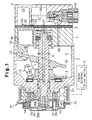
As shown in Fig. 1, the compressor includes a cylinder
block 1, a front housing member 2, and a rear housing member
4. The front housing member 2 is secured to the front end of
the cylinder block 1. The rear housing member 4 is secured to
the rear end of the cylinder block 1. A valve plate 3 is
secured between the cylinder block 1 and the rear housing
member 4. The cylinder block 1, the front housing member 2,
and the rear housing member 4 form the housing assembly of the
compressor. In Fig. 1, the left side of the figure is defined
as the front, and the right side of the figure is defined as
the rear.
A crank chamber 5 is defined between the cylinder block 1
and the front housing member 2. A drive shaft 6 is rotatably
supported in the crank chamber 5. A lug plate 11 is located
in the crank chamber 5 and is secured to the drive shaft 6 to
integrally rotate with the drive shaft 6.
The front end of the drive shaft 6 is coupled to the
engine E of a vehicle by means of a power transmitting
mechanism PT. In this embodiment, the engine E functions as
the external drive source. The power transmitting mechanism
PT may be a clutch mechanism (such as an electromagnetic
clutch), which selectively transmits and disconnects power by
external electrical control. The power transmitting mechanism
PT may also be a clutchless type mechanism (such as a
combination of a belt and a pulley), which does not have a
clutch mechanism and constantly transmits power. The
clutchless type power transmitting mechanism PT is employed in
the first embodiment. A power transmitting mechanism PT that
is used with a clutch will be described in the second
embodiment.
A swash plate 12 is accommodated in the crank chamber 5.
The swash plate 12 is supported by the drive shaft 6 to slide
and to incline. A hinge mechanism 13 is arranged between the
lug plate 11 and the swash plate 12. Accordingly, the swash
plate 12 rotates integrally with the lug plate 11 and the
drive shaft 6 by means of the hinge mechanism 13. The swash
plate 12 inclines with respect to the drive shaft 6 while
sliding along the axis of the drive shaft 6.
Cylinder bores 1a (only one of the cylinder bores is
shown in Fig. 1) are formed in the cylinder block 1 to
encompass the drive shaft 6. Each cylinder bore 1a is formed
through the cylinder block 1. A single-headed piston 20 is
housed in each cylinder bore 1a. The valve plate 3 closes the
rear opening of each cylinder bore 1a and the piston 20 closes
the front opening of each cylinder bore 1a. A compression
chamber is defined in each cylinder bore 1a. The volume of
the compression chamber varies as each piston 20 reciprocates
in the corresponding cylinder bore 1a. Each piston 20 is
coupled to the periphery of Lhe swash plate 12 by a pair of
shoes 19. Therefore, when the swash plate 12 rotates
integrally with the drive shaft 6, rotation of the swash plate
12 reciprocates each piston 20 by means of the pair of shoes
19.
A suction chamber 21 and a discharge chamber 22 are
respectively defined between the valve plate 3 and the rear
housing member 4. A suction port 23 and a suction valve 24,
which selectively opens and closes the port 23, are formed in
the valve plate 3 for each cylinder bore 1a. A discharge port
25 and a discharge valve 26, which selectively opens and
closes the port 25, are formed in the valve plate 3 for each
cylinder bore 1a. The suction chamber 21 and each cylinder
bore 1a are connected by the corresponding suction port 23.
Each cylinder bore 1a and the discharge chamber 22 are
connected by the corresponding discharge port 25.
The movement of each piston 20 from the top dead center
to the bottom dead center draws refrigerant gas in the suction
chamber 21 into the associated cylinder bore 1a through the
corresponding suction port 23 and the corresponding suction
valve 24. The movement of each piston 20 from the bottom dead
center to the top dead center compresses the refrigerant gas
drawn into the associated cylinder bore 1a, to a predetermined
pressure. Then, the compressed refrigerant gas is discharged
to the discharge chamber 22 through the corresponding
discharge port 25 and the corresponding discharge valve 26.
In the above mentioned compressor, the inclination angle
of the swash plate 12 is arbitrarily set between the maximum
inclination angle (as shown in Fig. 1) and the minimum
inclination angle by adjusting the internal pressure of the
crank chamber 5 using an electromagnetic control valve CV.
The crank chamber 5 and the suction chamber 21 are
connected by a bleed passage 27. The discharge chamber 22 and
the crank chamber 5 are connected by a supply passage 28, in
which the electromagnetic control valve CV is located. The
flow rate of highly pressurized discharge gas that is
conducted to the crank chamber 5 from the discharge chamber 22
through the supply passage 28 is set by adjusting the opening
degree of the electromagnetic control valve CV using a control
apparatus, which is not shown in the figures. The internal
pressure of the crank chamber 5 is determined by the
relationship between the flow rate of gas entering the crank
chamber 5 and the flow rate of gas that is flowing from the
crank chamber 5 into the suction chamber 21 through the bleed
passage 27. The difference between the internal pressure of
the crank chamber 5 and the internal pressure of each cylinder
bore 1a changes according to the internal pressure of the
crank chamber 5. The inclination angle of the swash plate 12
is determined by this pressure difference. As a result, the
stroke of each piston 20, or the displacement, is adjusted.
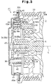
As shown in Figs. 2 and 3, the exterior wall of the front
housing member 2 protrudes to form a support cylinder that
surrounds the front end of the drive shaft 6. A pulley 32,
which functions as a first rotor, includes a cylindrical belt
engaging member 32a and an annular support member 32b. A belt
33, which extends from the output axis of the engine E (refer
to Fig. 1), is wrapped around the cylindrical belt engaging
member 32a. The annular support member 32b is inward of the
inner surface of the belt engaging member 32a. The support
member 32b is rotatably supported by the support cylinder 31
through a bearing 34. The pulley 32 is located around the
same axis as the axis L of the drive shaft 6 and rotates
relative to the drive shaft 6.
A receiving member 35, which functions as a second rotor,
is secured to the front end of the drive shaft 6 to integrally
rotate with the drive shaft 6. The rocciving member 35
includes a cylindrical member 35a and a disc-shaped hub 35b.
The cylindrical member 35a is fitted on the front end of the
drive shaft 6. The hub 35b is fitted into the front end of
the cylindrical member 35a.
Support pins 36 (four support pins are used in this
embodiment) are secured to the periphery of the hub 35b at
equal angular intervals (90 degrees in this embodiment) about
the axis L. A cylindrical sleeve 37 is fitted on the
periphery of each support pin 36 with an appropriate pressure.
When a strong rotational force is applied to one of the
sleeves 37, it can rotate relative to the corresponding
support pin 36.
Engaging pins 38 (four engaging pins are applied in this
embodiment) are secured to the front surface of the support
member 32b of the pulley 32 at equal angular intervals (90
degrees in this embodiment) about the axis L. A cylindrical
roller 39 is rotatably supported by each engaging pin 38. The
engaging pins 38 are further from the axis L than the support
pins 36.
In the pulley 32, an annular fitting groove 32c is formed
at the front portion of the belt engaging member 32a. The
periphery of an annular stopper 40, which is a flat ring, is
fitted in the fitting groove 32c. A cylindrical limit ring 41
is connected to the pulley 32 by the inner edge of the stopper
40. The limit ring 41 is coaxial with the pulley 32 and
encompasses the rollers 39. The middle section of the inner
surface of Lhe limit ring 41 bulges inwardly, as shown, and
forms a limit surface 41a.
A power transmission arm 42 is formed by a leaf spring
and is located between each sleeve 37 and one of the rollers
39. The proximal end of each power transmission arm 42 is
securely wound around the sleeve 37 of the corresponding
support pin 36. Each power transmission arm 42 extends from
the corresponding sleeve 37 toward the corresponding roller 39
in a clockwise direction as viewed from the perspective of
Fig. 2. Each power transmission arm 42 is slightly arched
toward the periphery of the pulley 32 as shown.
The distal end of each power transmission arm 42 is
between the corresponding roller 39 and the limit surface 41a
of the limit ring 41. In other words, the distal end of each
power transmission arm 42 is closer to the periphery of the
pulley 32 than the corresponding roller 39. The distal end of
each power transmission arm 42 curves inwardly as shown in
Fig. 2. Therefore, a curved end 43, which is hooked around
the corresponding roller 39, is formed at the distal end of
each power transmission arm 42. In other words, each power
transmission arm 42 of the receiving member 35 is engaged with
the corresponding roller 39 by the curved end 43. The
receiving member 35 and the pulley 32 are connected with each
other by the arms 42 to transmit power and to rotate relative
to one another within a predetermined angular range while
transmitting power.
According to this embodiment, each roller 39 and the
corresponding curved end 43 are located about the axis L of
the rotors 32, 35. Each roller 39 is radially inward of the
corresponding curved end 43. Each power transmission arm 42
is supported by the receiving member 35 and the corresponding
support pin 36. The support pins 36 are closer to the axis L
than the corresponding curved ends 43.
A fulerum portion 44 is formed on a back surface 42a of
each power transmission arm 42 to oppose the limit surface 41a
of the limit ring 41. The fulcrum portions are formed by, for
example, attaching a piece of vulcanized rubber to each arm
42. Each fulcrum portion 44 is compressed between the back
surface 42a of the corresponding power transmission arm 42 and
the limit surface 41a of the limit ring 41. Each power
transmission arm 42 is pressed against the corresponding
roller 39 by the repulsive force of the corresponding fulcrum
portion 44. In this state, the cylindrical surface 39a of
each roller 39 is pressed against a concave surface 43a of the
corresponding curved end 43 of each power transmission arm 42.
The radius of curvature of the cylindrical surface 39a of each
roller 39 is less than the radius of curvature of the concave
surface 43a inside the corresponding curved end 43, thus
linear contact occurs between each cylindrical surface 39a and
the corresponding concave surface 43a.
The concave surface 43a of each curved end 43 is curved.
Thus, the inclination of a tangent to the curve of each arm
increases at the distal and proximal ends. In the state shown
in Fig. 2, the contact point between the cylindrical surface
39a of each roller 39 and the concave surface 43a of the
corresponding curved end 43 moves toward the distal end or
toward the proximal end of the corresponding power
transmission arm 42 when one of the rollers 39 and the
corresponding power transmission arm 42 move relative to one
another. As a result, each roller 39 applies force to the
corresponding power transmission arm 42 in an outward
direction when the pulley 32 is driven.
A cover 45 has a cylindrical shape with a closed end. A
flange 45a, which is formed at the periphery of the cover 45,
is fitted in the fitting groove 32c together with the outer
edge of the stopper 40. The cover 45 is used to cover the
front end of the pulley 32. Each member that transmits power
between the pulley 32 and the drive shaft 6 (receiving member
35, support pins 36, engaging pins 38, rollers 39, limit ring
41, and power transmission arms 42) is accommodated in the
space between the cover 45 and the pulley 32. An annular
sealing member 47 is fitted in the fitting groove 32c along a
side wall surface. The sealing member 47 contacts the flange
45a of the cover 45 to seal the space between the cover 45 and
the pulley 32.
Operation of the Power transmitting mechanism
The engine E transmits power to the pulley 32 via the
belt 33. The power is then transmitted to the receiving
member 35 by the rollers 39 and the power transmission arms
42. The power is then transmitted to the drive shaft 6 of the
compressor. Load torque is generated between the receiving
member 35 of the compressor and the pulley 32 of the engine E
during power transmission. The load torque causes each roller
39 and the corresponding power transmission arm 42 to move
relative to one another, which causes the pulley 32 and the
receiving member 35 to rotate relative to one another.
As shown in Fig. 4, when the pulley 32 rotates clockwise,
the load torque tends to rotate the receiving member 35
counter-clockwise with respect to the pulley 32. Therefore,
each roller 39 and the corresponding power transmission arm 42
tend to move relative to one another. The contact points
between them move toward the distal ends of the power
transmission arms 42. The location where the fulcrum portion
44 presses against the limit surface 41a of the limit ring 41
functions as a fulcrum. Then, the distal end of the power
transmission arm 42 is elastically deformed generally outward.
That is, the power transmission arm 42 is elastically deformed
based on the load torque. Thus, the curved end 43 changes
attitude with respect to the receiving member 35, in other
words, the concave surface 43a is deformed.
When the displacement of the compressor increases and the
load torque is increased, the force that elastically deforms
the distal end of each power transmission arm 42 generally
outward is increased. Therefore, each roller 39 further
elastically deforms the corresponding power transmission arm
42 and relatively moves to the distal end of the corresponding
power transmission arm 42. As a result, each roller 39
rotates along the corresponding concave surface 43a and the
contact point further moves toward the distal end of the
corresponding power transmission arm 42. Accordingly; the
relative rotation angle between the pulley 32 and the
receiving member 35 is increased.
However, when the displacement of the compressor
decreases and the load torque is decreased, the force that
elastically deforms the distal end of each power transmission
arm 42 generally outward is decreased. Therefore, some of the
energy that is accumulated in each power transmission arm 42
is released and the roller 39 relatively move to the proximal
ends of the corresponding power transmission arms 42. As a
result, each roller 39 rotates along the concave surface 43a
and the contact point moves to the proximal end of the
corresponding power transmission arm 42. Accordingly, the
relative rotation angle of the pulley 32 and the receiving
member 35 is decreased.
When the compressor is actually driven by the engine E,
the output torque of the engine E or the driving torque of the
auxiliary equipment, for example, a hydraulic pump of a power
steering apparatus, fluctuates. Thus, the power that is
transmitted from the pulley 32 to the receiving member 35
varies. In this case, the position of the contact point is
changed repeatedly. In other words, the pulley 32 repeats
relative rotation in the clockwise and counter-clockwise
direction within the predetermined angular range. Thus, the
fluctuation of power that is transmitted from the pulley 32 to
the receiving member 35 is suppressed.
When the amount of the load torque does not adversely
affect the engine E, that is, when the load torque is smaller
than the maximum allowable torque, the contact point is kept
on the concave surface 43a. In other words, each roller 39
and the corresponding curved end 43 are kept engaged and the
power transmission from the engine E to the drive shaft 6 is
continued.
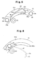
However, as shown in Fig. 5, when an abnormality occurs
in the compressor, or when the compressor is locked, the load
torque becomes equal to or greater than the maximum torque.
In this case, the stiffness of each power transmission arm 42
is insufficient to keep the contact point on the concave
surface 43a. Accordingly, the roller 39 moves beyond the
curved end 43 to the distal end of the power transmission arm
42 and separates from the concave surface 43a. Thus, each
roller 39 and the corresponding power transmission arm 42 are
disengaged. Therefore, the power transmission between the
pulley 32 and the receiving member 35 is disconnected. This
prevents the engine E from being affected by excessive load
torque.
After each roller 39 and the corresponding power
transmission arm 42 are disengaged, a next roller 39 on the
pulley 32 contacts the back surface 42a of the corresponding
power transmission arm 42 due to the free relative rotation of
the pulley 32 with respect to the receiving member 35. This
rotates the corresponding power transmission arm 42 about the
corresponding support pin 36, as shown in Fig. 6. As a
result, the corresponding power transmission arms 42 are
rotated clockwise with the respective sleeves 37 about the
respective support pins 36. Thus, the power transmission arms
42 change position with respect to the receiving member 35.
The curved end 43 of each power transmission arm 42 is
closer to the periphery of the pulley 32 than the roller 39
just after the arm 42 comes off the roller 39. However, the
curved end 43 of each power transmission arm 42 is moved
closer to the center of the pulley 32 than the roller 39 after
the pulley rotates by a quarter revolution, or in other words,
after each roller 39 contacts the corresponding power
transmission arm 42 at the back surface 42a. Each support pin
36 is inserted in the corresponding sleeve 37 with an
appropriate pressure. Thus, even if an external force is
applied, for example, by the vehicle vibration, the power
transmission arms 42 reliably keeps the rollers 39 from being
engaged (as shown in Fig. 6). Accordingly, the rollers 39 do
not interfere with the power transmission arms 42 (or curved
ends 43). Thus, power transmission between the pulley 32 and
the receiving member 35 is reliably disconnected.
Interference between the roller 39 and the power transmission
arms 42, which would apply load against the engine E and would
cause a loss of engine power, is prevented. This structure
prevents the roller 39 and the power transmission arm 42 from
hitting each other repeatedly and thus causing noise and
vibration.
This embodiment provides the following advantages.
The invention minimizes the loss of fuel efficiency by
reliably discontinuing power transmission between the pulley
32 and the receiving member 35 when the load torque between
the pulley 32 and the receiving member 35 is excessive.
The position of each power transmission arm 42 is changed
by rotating it about the corresponding support pin 36 when the
curved ends 43 and the corresponding rollers 39 are
disengaged. Therefore, compared with a structure that changes
the position of the power transmission arm 42 by deformation,
the change of position is performed more smoothly.
The rollers 39 and the engine E are used for changing the
position of the power transmission arms 42. Accordingly, no
special member, such as springs, is required for changing the
position of the power transmission arms 42. Thus, the
structure of the power transmitting mechanism is simplified.
The cylindrical surface 39a of each roller 39 rolls along
the concave surface 43a of the corresponding curved end 43
repeatedly against the friction between the cylindrical
surface 39a and the concave surface 43a. This reduces torque
shock applied to the engine.
Each roller 39 rotates while sliding along the concave
surface 43a of the corresponding curved end 43. Compared with
an engaging pin 38, which does not rotate while directly
contacting the concave surface 43a of the corresponding curved
end 43 (such an engaging pin is also within the concept of the
present invention), the likelihood of a malfunction in
slidability is reduced. Thus, fluctuation of power
transmission is effectively suppressed.
Compared with a concave surface 43a that is formed by a
combination of planar surfaces with different inclination
angles (such a concave surface is also within the concept of
the present invention), each roller 39 smoothly rolls on the
corresponding concave surface 43a. This permits smooth
relative rotation between the pulley 32 and the receiving
member 35. Thus, smooth power transmission is achieved, and
fluctuation of power transmission is effectively suppressed.
Each curved end 43 is connected Lo the hub 35b by means
of the corresponding power transmission arm 42, which
functions as an elastic member. Thus, each curved end 43
changes position with respect to the hub 35b by elastic
deformation of the corresponding power transmission arm 42.
In other words, the elastic arms 42 add elasticity to the
transmission apparatus. Compared with a case, for example,
where separate elastic members are provided in addition to the
coupler, the number of power transmission members are reduced.
The position of the contact point changes along the
concave surface 43a repeatedly when the transmitted power
varies. Accordingly, the distance between the contact point
and the fulcrum of the deformation of the corresponding power
transmission arm 42 (contact point between each fulcrum
portion 44 and the limit ring 41) changes. The modulus of
elasticity of the power transmission arm 42 and resonance
frequency constantly change accordingly. Thus, the mechanism
prevents the resonance from being generated by the vibration
of the relative rotation, which is based on the variation of
the transmitted power, of the pulley 32 and the receiving
member 35.
Each power transmission arm 42 is formed by a leaf
spring. Each curved end 43 is formed by curving the
corresponding power transmission arm 42. Therefore, the
curved ends 43 are easily formed.
Each power transmission arm 42 elastically deforms in the
radial direction of the pulley 32 (each curved end 43 changes
shape) when the torque is transmitted. Each power
transmission arm 42 also rotates to position inwardly in the
radial direction of the pulley 32 when the torque transmission
is disconnected. Therefore, no space is required in the
direction of the axis L for deformation and rotation of each
power transmission arm 42. Thus, the size of the power
transmitting mechanism PT, more specifically, the size of the
compressor, which has the power transmitting mechanism PT, is
miniaturized in the direction of axis L. The space allotted
for the compressor in an engine compartment of a vehicle is
limited. For an air-conditioning compressor in a vehicle,
miniaturization in the direction of the axis L is preferred
over miniaturization in the radial direction. Accordingly,
the power transmitting mechanism PT in the first embodiment
has a suitable structure for a compressor of a vehicle air-conditioning
system. The elastic deformation of each power
transmission arm 42 does not generate the reaction force in
the direction of axis L of the drive shaft 6. Thus, the
mechanism prevents force from acting on the compressor in the
direction of axis L, which adversely affects the compressor.
The pulley 32 includes the cover 45. Each member that
transmits power (such as the receiving member 35, the support
pins 36, the engaging pins 38, the rollers 39, the limit ring
41, and the power transmission arms 42) is accommodated in the
space between the cover 45 and the pulley 32. This structure
prevents foreign objects and water, oil, or dust in the engine
compartment of a vehicle from affecting the transmission
parts. Thus, wear resulting from the contamination of the
members is eliminated. The structure also prevents foreign
objects from being caught between the cylindrical surface 39a
of each roller 39 and the concave surface 43a of the
corresponding curved end 43. Accordingly, smooth rotation of
the rollers 39 is maintained.
Second Embodiment
In the second embodiment, only the parts different from
the first embodiment are explained. Like members are given
like numbers and detailed explanations are omitted.
In the second embodiment, a pulley 32 has an
electromagnetic clutch, which selectively transmits and
disconnects power by external electrical control, as shown in
Fig. 7. A cover 45 is supported by a hub 35b of a receiving
member 35. A leaf spring 51 is located hetween the cover 45
and the hub 35b. An armature 52 is secured to the cover 45
and is located between the pulley 32 and a limit ring 41.
Engaging pins 38 are secured to the armature 52. The limit
ring 41 is not engaged with the pulley 32 and is fitted on the
power transmission arm 42. A core 53 is located at the rear
of the pulley 32 in the front housing member 2.
When the core 53 is excited by the externally applied
power, the armature 52 and the cover 45 is drawn towards the
pulley 32 with the rollers 39 against the leaf spring 51.
Therefore, a clutch surface 52a of the armature 52 is pressed
against a clutch surface 32d of the pulley 32. Thus, power is
transmitted between the pulley 32 and the engaging pin 38 (or
the roller 39).
In this state, when the core 53 is demagnetized by
stopping the current supply, the force of the leaf spring 51
urges the armature 52 and the cover 45 with the roller 39 away
from the pulley. Therefore, the clutch surface 32d and 52a
are separated, thus, power transmission between the pulley 32
and the engaging pin 38 is disconnected.
In the second embodiment, for example, a compressor may
be stopped by an external control when air-conditioning is not
required. Thus, loss of power of an engine E is reduced.
It should be apparent to those skilled in the art that
the present invention may be embodied in many other specific
forms without departing from the spirit or scope of the
invention. Particularly, it should be understood that the
invention may be embodied in the following forms.
Elasticity need not be provided in the power transmission
path. That is, the power transmission arms 42 may be rigid
bodies in the above embodiments. Instead, the limit ring 41
may be formed of an elastic material, which elastically
deforms to radially expand and contract. Thus, each power
transmission arm 42 (curved end 43) rotates about the
corresponding support pin 36 according to the load torque when
the roller 39 and the curved end 43 are engaged. As a result,
each curved end 43 changes position with respect to the
receiving member 35.
The engaging pins 38 may be closer to the axis L than the
pins 36.
In the illustrated embodiments, four pairs of rollers 39
and power transmission arms 42 are provided. The number of
pairs is not limited to four, but may be six, five, three,
two, or one. If the number of the pairs is reduced, the
assembly of the power transmitting mechanism is simplified and
the cost is reduced. If the number of the pairs is increased,
the amount of transmission torque transmitted by each pair is
reduced. Thus the endurance of each roller 39 and the
corresponding power transmission arm 42 is improved. In other
words, the endurance of the power transmitting mechanism PT is
improved.
A part of the back surface 42a of each power transmission
arm 42 may be deformed to integrally form the fulcrum portion
44.
Balls may be used instead of rollers 39 as a rotating
element.
The rollers may be arranged to change position with
respect to the rotor on which the rollers are located, instead
of the curved ends. For example, the curved ends 43 may be
fixed instead of Lhe engaging pins 38. The rollers 39 may be
provided on the distal ends of Lhe power transmission arms 42
to engage with the corresponding curved ends 43.
Both curved ends 43 and the rollers 39 may be arranged to
change position with respect to the rotors 32 and 35,
respectively.
A spring, which urges each power transmission arm 42
radially inward, may be provided between each power
transmission arm 42 and the corresponding receiving member 35.
Each spring changes the position of the corresponding power
transmission arm 42. Each spring may be arranged to pull the
corresponding power transmission arm 42 toward the drive shaft
6. Each spring may also be provided between one of the
support pins 36 and the corresponding sleeve 37 to rotate the
sleeve 37. In this case, when the rollers 39 and the
corresponding power transmission arms 42 are disengaged, the
power transmission arms 42 rotate to the withdrawn position
without contacting the rollers 39. That is, the corresponding
power transmission arms 42 change position with respect to the
receiving member 35. This reliably prevents noise and
vibration caused by collision of the arms 42 and the rollers
39.
The second embodiment may be modified to include an
electromagnetic clutch structure between the receiving member
35 and the drive shaft 6.
The use of the torque transmitting mechanism of the above
embodiments is not limited to power transmission between an
engine E and an air-conditioning compressor. The mechanism
may be used for power transmission between an engine E and any
auxiliary device (such as a hydraulic pump for a power
steering apparatus or a cooling fan for a radiator). The
application of the power transmitting mechanism of the above
embodiments is not limited to a power transmission path of a
vehicle. The mechanism may be used for a power transmission
path between a drive source and in a machine tool. The power
transmitting mechanism of the above embodiments has general
versatility and may be applied to any power transmission path.
Therefore, the present examples and embodiments are to
be considered as illustrative and not restrictive and the
invention is not to be limited to the details given herein,
but may be modified within the scope and equivalence of the
appended claims.
A power transmitting mechanism transmits power from an
engine to a drive shaft (6) of a compressor. A pulley (32) is
supported by the compressor and is coupled to the engine. A
hub (35b) is attached to the drive shaft (6). Rollers (39)
are located on the pulley (32). Elastic transmission arms
(42) are located between the pulley (32) and the hub (35b).
The distal end of each arm (42) is curved, and the proximal
end is coupled to the hub (35b). When the rollers are engaged
with the arms (42), power is transmitted between the pulley
(32) and the hub (35b). When, due to excessive torque, the
rollers (39) escape from the corresponding arm (42), power
transmission between the pulley (32) and the hub (35b) is
disconnected. The distal ends of the arms (42) are movable in
the radial direction. When the rollers (39) disengage from
the corresponding arms (42), the distal ends of the arms (42)
move radially such that the pulley (32) and the hub (35b)
relatively rotate without interference by the arms (42).