EP1179660A2 - Ausgleichsbehälter für ein Brennkraftmaschinen-Kühlsystem, insbesondere in Fahrzeugen - Google Patents
Ausgleichsbehälter für ein Brennkraftmaschinen-Kühlsystem, insbesondere in Fahrzeugen Download PDFInfo
- Publication number
- EP1179660A2 EP1179660A2 EP01115988A EP01115988A EP1179660A2 EP 1179660 A2 EP1179660 A2 EP 1179660A2 EP 01115988 A EP01115988 A EP 01115988A EP 01115988 A EP01115988 A EP 01115988A EP 1179660 A2 EP1179660 A2 EP 1179660A2
- Authority
- EP
- European Patent Office
- Prior art keywords
- chamber
- partition
- expansion tank
- vertical chamber
- horizontal
- Prior art date
- Legal status (The legal status is an assumption and is not a legal conclusion. Google has not performed a legal analysis and makes no representation as to the accuracy of the status listed.)
- Granted
Links
- 238000001816 cooling Methods 0.000 title claims abstract description 14
- 238000002485 combustion reaction Methods 0.000 title claims description 6
- 238000005192 partition Methods 0.000 claims abstract description 29
- 238000009434 installation Methods 0.000 claims description 8
- 239000000110 cooling liquid Substances 0.000 claims description 4
- 239000000945 filler Substances 0.000 claims description 3
- 239000012809 cooling fluid Substances 0.000 abstract 1
- 239000002826 coolant Substances 0.000 description 8
- 239000007788 liquid Substances 0.000 description 3
- 238000006073 displacement reaction Methods 0.000 description 2
- 238000009423 ventilation Methods 0.000 description 2
- 230000001133 acceleration Effects 0.000 description 1
- 230000000694 effects Effects 0.000 description 1
- 230000007774 longterm Effects 0.000 description 1
- 238000004519 manufacturing process Methods 0.000 description 1
- 238000012986 modification Methods 0.000 description 1
- 230000004048 modification Effects 0.000 description 1
- 238000013021 overheating Methods 0.000 description 1
Images

Classifications
-
- F—MECHANICAL ENGINEERING; LIGHTING; HEATING; WEAPONS; BLASTING
- F01—MACHINES OR ENGINES IN GENERAL; ENGINE PLANTS IN GENERAL; STEAM ENGINES
- F01P—COOLING OF MACHINES OR ENGINES IN GENERAL; COOLING OF INTERNAL-COMBUSTION ENGINES
- F01P11/00—Component parts, details, or accessories not provided for in, or of interest apart from, groups F01P1/00 - F01P9/00
- F01P11/02—Liquid-coolant filling, overflow, venting, or draining devices
- F01P11/029—Expansion reservoirs
Definitions
- the invention relates to a preamble of claim 1 Expansion tank for an internal combustion engine cooling system, in particular in vehicles, in the installed position a vertical chamber and one to it in a geodetic higher area arranged horizontal chamber, wherein the vertical chamber a filler neck in its upper end area and in its lower end area a connector on the cooling system side is assigned.
- Such a surge tank is known for example from DE 42 43 404 A1, which is known to be connected in a closed coolant circuit and flows through one or more bypasses.
- the flow this expansion tank has the effect of permanent ventilation of the coolant circuit.
- the invention has for its object a generic expansion tank to further develop such that with a relatively low liquid level in the Vertical chamber a safe amount of liquid to prevent air intake a vehicle inclination or by a dynamically induced shift of the Coolant over the cooling system-side connection piece of the expansion tank or the vertical chamber remains.
- connection channel is on the one hand into the horizontal chamber near the bottom of the partition and on the other hand into the vertical chamber with a Lower edge of the mouth at least at the level of the bottom of the horizontal chamber the partition opens out spaced in the direction of the connecting piece.
- the advantage of the invention is that at a relatively low level of cooling liquid the given in the vertical chamber with the partition according to the invention Coolant is prevented when the vehicle is at an incline or to evade the horizontal chamber in the event of operational dynamic displacement. This means that there is a relatively low coolant level in the vertical chamber ensures that the existing coolant remains in it and an air intake in the rest of the cooling system is safely avoided.
- An advantageous development of the invention is also achieved in that a vertical chamber with a relatively small volume due to installation the partition in the horizontal chamber is staggered.
- the Partition beyond the angled section for a one-piece connection is extended with the side boundary and an opening arranged on the bottom has in the connecting channel.
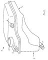
- An expansion tank 1 for an internal combustion engine cooling system not shown in a vehicle according to the installation position shown in FIG Expansion tank 1, a vertical chamber 2 and one of these in a geodetic higher area arranged horizontal chamber 3, wherein the vertical chamber 2 in a filler neck 4 in its end region and a cooling system side in its lower end region Connection piece 5 is assigned.
- Partition 8 is arranged, which is used at a relatively low level of cooling liquid in the vertical chamber 2 this amount of liquid for operational reasons Oblique position or operationally related dynamic displacement in the vertical chamber 2 withhold.
- both chambers 2 and 3 are in the normal installation position via a separate connection channel in a communicating connection are such that the connection channel on the one hand into the horizontal chamber 3 near the bottom of the partition 8 and on the other hand in the vertical chamber 2 with a Muzzle lower edge 10 at least at the level of the bottom 11 of the horizontal chamber 3 spaced from the partition 8 in the direction of the connecting piece 5 empties.
- the connection channel on the one hand into the horizontal chamber 3 near the bottom of the partition 8 and on the other hand in the vertical chamber 2 with a Muzzle lower edge 10 at least at the level of the bottom 11 of the horizontal chamber 3 spaced from the partition 8 in the direction of the connecting piece 5 empties.
- connecting channel 9 is among others thereby achieved that with a common side boundary 12 of the vertical chamber 2 and horizontal chamber 3 an angled partition 8 is provided, the angled portion 8 'and the adjacent side boundary 12 the connecting channel 9 with a level with the bottom 11 of the horizontal chamber 3 run channel bottom 13 form.
- the horizontal chamber can be stiffened 3 can be achieved in that the partition 8 over the angled Section 8 'also for one-piece connection with the side boundary 12 is extended and an opening 14 arranged on the bottom in the connecting channel 9 has.
- the horizontal chamber 3 through to the partition 8th stiffen and parallel other walls crossing to the partition 8 divide to dampen surge movements of the coolant.
Landscapes
- Engineering & Computer Science (AREA)
- Chemical & Material Sciences (AREA)
- Combustion & Propulsion (AREA)
- Mechanical Engineering (AREA)
- General Engineering & Computer Science (AREA)
- Cooling, Air Intake And Gas Exhaust, And Fuel Tank Arrangements In Propulsion Units (AREA)
Abstract
Description
- Figur 1
- einen erfindungsgemäßen Ausgleichsbehälter in Gesamtansicht,
- Figur 2
- den Unterteil des Ausgleichsbehälter nach Figur 1 mit der erfindungsgemäßen Trennwand.
Claims (4)
- Ausgleichsbehälter für ein Brennkraftmaschinen-Kühlsystem, insbesondere in Fahrzeugen,dadurch gekennzeichnet,der in Einbaulage eine Vertikalkammer (2) und eine an diese in einem geodätisch höheren Bereich angeordnete Horizontalkammer (3) umfasst, wobeider Vertikalkammer (2) in ihrem oberen Endbereich ein Einfüllstutzen (4) undin ihrem unteren Endbereich ein kühlsystemseitiger Anschlussstutzen (5) zugeordnet ist,dass zwischen der Vertikalkammer (2) und der Horizontalkammer (3) eine die Kühlflüssigkeit in der Vertikalkammer (2) zurückhaltende Trennwand (8) angeordnet ist, wobeibeide Kammern (2, 3) in normaler Einbaulage über einen gesonderten Verbindungskanal (9) in kommunizierender Verbindung stehen derart, dassder Verbindungskanal (9) einerseits in die Horizontalkammer (3) bodennah der Trennwand (8) und andererseitsin die Vertikalkammer (2) mit einer Mündungsunterkante (10) mindestens in Höhe des Bodens (11) der Horizontalkammer (3) von der Trennwand (8) in Richtung des Anschlussstutzens (5) beabstandet angeordnet mündet.
- Ausgleichsbehälter nach Anspruch 1, dadurch gekennzeichnet, dass bei einer Vertikalkammer (2) mit einbaubedingt relativ kleinem Volumen die Trennwand (8) in die Horizontalkammer (3) versetzt angeordnet ist.
- Ausgleichsbehälter nach Anspruch 2, dadurch gekennzeichnet,dass bei einer gemeinsamen Seitenbegrenzung (12) von Vertikalkammer (2) und Horizontalkammer (3) eine abgewinkelt ausgebildete Trennwand (8) vorgesehen ist, derenabgewinkelter Abschnitt (8') und die benachbarte Seitenbegrenzung (12) den Verbindungskanal (9) mit einem in Höhe des Bodens (11) der Horizontalkammer (3) verlaufenden Kanalgrund (13) bilden.
- Ausgleichsbehälter nach Anspruch 3, dadurch gekennzeichnet,dass die Trennwand (8) über den abgewinkelten Abschnitt (8') hinaus zur einstückigen Verbindung mit der Seitenbegrenzung (12) verlängert ist undeine bodenseitig angeordnete Durchbrechung (14) in den Verbindungskanal (9) aufweist.
Applications Claiming Priority (2)
| Application Number | Priority Date | Filing Date | Title |
|---|---|---|---|
| DE10039019A DE10039019A1 (de) | 2000-08-10 | 2000-08-10 | Ausgleichsbehälter für ein Brennkraftmaschinen-Kühlsystem, insbesondere in Fahrzeugen |
| DE10039019 | 2000-08-10 |
Publications (3)
| Publication Number | Publication Date |
|---|---|
| EP1179660A2 true EP1179660A2 (de) | 2002-02-13 |
| EP1179660A3 EP1179660A3 (de) | 2003-08-06 |
| EP1179660B1 EP1179660B1 (de) | 2004-12-08 |
Family
ID=7651951
Family Applications (1)
| Application Number | Title | Priority Date | Filing Date |
|---|---|---|---|
| EP01115988A Expired - Lifetime EP1179660B1 (de) | 2000-08-10 | 2001-06-30 | Ausgleichsbehälter für ein Brennkraftmaschinen-Kühlsystem, insbesondere in Fahrzeugen |
Country Status (3)
| Country | Link |
|---|---|
| EP (1) | EP1179660B1 (de) |
| DE (2) | DE10039019A1 (de) |
| ES (1) | ES2228702T3 (de) |
Cited By (1)
| Publication number | Priority date | Publication date | Assignee | Title |
|---|---|---|---|---|
| CN114439596A (zh) * | 2020-10-30 | 2022-05-06 | 重庆长安汽车股份有限公司 | 一种车用蓄水瓶及具有其的车辆 |
Families Citing this family (2)
| Publication number | Priority date | Publication date | Assignee | Title |
|---|---|---|---|---|
| CN103161560B (zh) * | 2011-12-15 | 2015-02-18 | 北汽福田汽车股份有限公司 | 用于发动机冷却系统的副水箱和发动机冷却系统 |
| CN109733625B (zh) * | 2018-12-28 | 2021-02-05 | 北京奥航坤宇科技有限公司 | 一种无人机新型硬壳式隔舱油箱 |
Citations (1)
| Publication number | Priority date | Publication date | Assignee | Title |
|---|---|---|---|---|
| DE4243404A1 (en) | 1991-12-23 | 1993-07-01 | Saab Scania Ab | Multichamber balancing container for vehicle cooling system - is made from two blow-moulded vessels joined by releasable coupling with valve |
Family Cites Families (2)
| Publication number | Priority date | Publication date | Assignee | Title |
|---|---|---|---|---|
| DE4328448C2 (de) * | 1993-08-24 | 1995-08-17 | Behr Gmbh & Co | Wärmetauscher |
| US5329889A (en) * | 1993-11-22 | 1994-07-19 | Molmec, Inc. | Degas tank for engine cooling system |
-
2000
- 2000-08-10 DE DE10039019A patent/DE10039019A1/de not_active Withdrawn
-
2001
- 2001-06-30 DE DE2001504746 patent/DE50104746D1/de not_active Expired - Lifetime
- 2001-06-30 EP EP01115988A patent/EP1179660B1/de not_active Expired - Lifetime
- 2001-06-30 ES ES01115988T patent/ES2228702T3/es not_active Expired - Lifetime
Patent Citations (1)
| Publication number | Priority date | Publication date | Assignee | Title |
|---|---|---|---|---|
| DE4243404A1 (en) | 1991-12-23 | 1993-07-01 | Saab Scania Ab | Multichamber balancing container for vehicle cooling system - is made from two blow-moulded vessels joined by releasable coupling with valve |
Cited By (2)
| Publication number | Priority date | Publication date | Assignee | Title |
|---|---|---|---|---|
| CN114439596A (zh) * | 2020-10-30 | 2022-05-06 | 重庆长安汽车股份有限公司 | 一种车用蓄水瓶及具有其的车辆 |
| CN114439596B (zh) * | 2020-10-30 | 2024-03-22 | 重庆长安汽车股份有限公司 | 一种车用蓄水瓶及具有其的车辆 |
Also Published As
| Publication number | Publication date |
|---|---|
| EP1179660B1 (de) | 2004-12-08 |
| ES2228702T3 (es) | 2005-04-16 |
| DE50104746D1 (de) | 2005-01-13 |
| DE10039019A1 (de) | 2002-03-07 |
| EP1179660A3 (de) | 2003-08-06 |
Similar Documents
| Publication | Publication Date | Title |
|---|---|---|
| DE3510890C2 (de) | ||
| DE102008060088B4 (de) | Ausgleichsbehälter für eine Kühlanlage | |
| DE69611016T2 (de) | Treibstoffversorgungssystem | |
| DE2827022A1 (de) | Wasserbehaelter als reservedruckbehaelter | |
| DE10310179B4 (de) | Ölauffangvorrichtung für eine Brennkraftmaschine, insbesondere für einen Boxermotor | |
| WO1986003554A1 (fr) | Radiateur en matiere plastique pour les systemes de refroidissement a ecoulement transversal des moteurs a combustion interne | |
| DE3533094A1 (de) | Ausgleichsbehaelter fuer kuehlfluessigkeit | |
| DE112012003486T5 (de) | Kraftstoffversorgungssystem und Siphonschutz-Strahlpumpe | |
| EP1164281B1 (de) | Kraftstoff-Förder- und Lüftungssystem | |
| DE10161403B4 (de) | Kraftstofffördereinheit | |
| DE2207693A1 (de) | Brennstoff-Hilfsspeicher | |
| EP0816152B1 (de) | Kraftstoff-Entnahmevorrichtung | |
| EP1045972B1 (de) | Kraftstoff-fördermodul | |
| EP1179660B1 (de) | Ausgleichsbehälter für ein Brennkraftmaschinen-Kühlsystem, insbesondere in Fahrzeugen | |
| DE10238237A1 (de) | Kammerentleerungseinrichtung | |
| DE102020103942A1 (de) | Motorölwanne und Brennkraftmaschine mit einer Motorölwanne | |
| DE10318050A1 (de) | Kraftstoffbehälter | |
| EP0979747A2 (de) | Befülleinrichtung | |
| DE4301761C2 (de) | Tanksystem für flüssigen Kraftstoff, insbesondere für Verbrennungsmotoren in Kraftfahrzeugen | |
| DE4228856B4 (de) | Flüssigkeitsgekühlte Brennkraftmaschine | |
| DE3702272A1 (de) | Tauchkolben fuer verbrennungsmotoren mit einem von kuehloel durchstroemten hohlraum | |
| EP0393654B1 (de) | Kühlsystem | |
| DE102008060411A1 (de) | Verbrennungsmotor | |
| EP1719657B1 (de) | In einem Kraftstoffbehälter angeordnete Fördereinheit | |
| DE10347736A1 (de) | Kraftstoffbehälter |
Legal Events
| Date | Code | Title | Description |
|---|---|---|---|
| PUAI | Public reference made under article 153(3) epc to a published international application that has entered the european phase |
Free format text: ORIGINAL CODE: 0009012 |
|
| AK | Designated contracting states |
Kind code of ref document: A2 Designated state(s): AT BE CH CY DE DK ES FI FR GB GR IE IT LI LU MC NL PT SE TR |
|
| AX | Request for extension of the european patent |
Free format text: AL;LT;LV;MK;RO;SI |
|
| PUAL | Search report despatched |
Free format text: ORIGINAL CODE: 0009013 |
|
| AK | Designated contracting states |
Designated state(s): AT BE CH CY DE DK ES FI FR GB GR IE IT LI LU MC NL PT SE TR |
|
| AX | Request for extension of the european patent |
Extension state: AL LT LV MK RO SI |
|
| RIC1 | Information provided on ipc code assigned before grant |
Ipc: 7F 28F 9/02 B Ipc: 7F 01P 11/02 A |
|
| 17P | Request for examination filed |
Effective date: 20030819 |
|
| AKX | Designation fees paid |
Designated state(s): DE ES FR GB IT |
|
| GRAP | Despatch of communication of intention to grant a patent |
Free format text: ORIGINAL CODE: EPIDOSNIGR1 |
|
| GRAS | Grant fee paid |
Free format text: ORIGINAL CODE: EPIDOSNIGR3 |
|
| GRAA | (expected) grant |
Free format text: ORIGINAL CODE: 0009210 |
|
| AK | Designated contracting states |
Kind code of ref document: B1 Designated state(s): DE ES FR GB IT |
|
| REG | Reference to a national code |
Ref country code: GB Ref legal event code: FG4D Free format text: NOT ENGLISH |
|
| GBT | Gb: translation of ep patent filed (gb section 77(6)(a)/1977) |
Effective date: 20041208 |
|
| REG | Reference to a national code |
Ref country code: IE Ref legal event code: FG4D Free format text: GERMAN |
|
| REF | Corresponds to: |
Ref document number: 50104746 Country of ref document: DE Date of ref document: 20050113 Kind code of ref document: P |
|
| REG | Reference to a national code |
Ref country code: ES Ref legal event code: FG2A Ref document number: 2228702 Country of ref document: ES Kind code of ref document: T3 |
|
| ET | Fr: translation filed | ||
| PLBE | No opposition filed within time limit |
Free format text: ORIGINAL CODE: 0009261 |
|
| STAA | Information on the status of an ep patent application or granted ep patent |
Free format text: STATUS: NO OPPOSITION FILED WITHIN TIME LIMIT |
|
| 26N | No opposition filed |
Effective date: 20050909 |
|
| PGFP | Annual fee paid to national office [announced via postgrant information from national office to epo] |
Ref country code: IT Payment date: 20120626 Year of fee payment: 12 |
|
| PG25 | Lapsed in a contracting state [announced via postgrant information from national office to epo] |
Ref country code: IT Free format text: LAPSE BECAUSE OF NON-PAYMENT OF DUE FEES Effective date: 20130630 |
|
| PGFP | Annual fee paid to national office [announced via postgrant information from national office to epo] |
Ref country code: GB Payment date: 20140626 Year of fee payment: 14 |
|
| PGFP | Annual fee paid to national office [announced via postgrant information from national office to epo] |
Ref country code: ES Payment date: 20140509 Year of fee payment: 14 |
|
| PGFP | Annual fee paid to national office [announced via postgrant information from national office to epo] |
Ref country code: DE Payment date: 20140702 Year of fee payment: 14 |
|
| PGFP | Annual fee paid to national office [announced via postgrant information from national office to epo] |
Ref country code: FR Payment date: 20140630 Year of fee payment: 14 |
|
| REG | Reference to a national code |
Ref country code: DE Ref legal event code: R119 Ref document number: 50104746 Country of ref document: DE |
|
| GBPC | Gb: european patent ceased through non-payment of renewal fee |
Effective date: 20150630 |
|
| REG | Reference to a national code |
Ref country code: FR Ref legal event code: ST Effective date: 20160229 |
|
| PG25 | Lapsed in a contracting state [announced via postgrant information from national office to epo] |
Ref country code: GB Free format text: LAPSE BECAUSE OF NON-PAYMENT OF DUE FEES Effective date: 20150630 Ref country code: DE Free format text: LAPSE BECAUSE OF NON-PAYMENT OF DUE FEES Effective date: 20160101 |
|
| PG25 | Lapsed in a contracting state [announced via postgrant information from national office to epo] |
Ref country code: FR Free format text: LAPSE BECAUSE OF NON-PAYMENT OF DUE FEES Effective date: 20150630 |
|
| REG | Reference to a national code |
Ref country code: ES Ref legal event code: FD2A Effective date: 20160801 |
|
| PG25 | Lapsed in a contracting state [announced via postgrant information from national office to epo] |
Ref country code: ES Free format text: LAPSE BECAUSE OF NON-PAYMENT OF DUE FEES Effective date: 20150701 |