EP1179138B1 - Method and system for generating a linear force from rotation - Google Patents
Method and system for generating a linear force from rotation Download PDFInfo
- Publication number
- EP1179138B1 EP1179138B1 EP00924991A EP00924991A EP1179138B1 EP 1179138 B1 EP1179138 B1 EP 1179138B1 EP 00924991 A EP00924991 A EP 00924991A EP 00924991 A EP00924991 A EP 00924991A EP 1179138 B1 EP1179138 B1 EP 1179138B1
- Authority
- EP
- European Patent Office
- Prior art keywords
- working body
- accordance
- deforming
- housing
- cylindrical
- Prior art date
- Legal status (The legal status is an assumption and is not a legal conclusion. Google has not performed a legal analysis and makes no representation as to the accuracy of the status listed.)
- Expired - Lifetime
Links
- 238000000034 method Methods 0.000 title claims abstract description 29
- 230000007246 mechanism Effects 0.000 claims abstract description 51
- 239000007787 solid Substances 0.000 claims abstract description 29
- 238000006243 chemical reaction Methods 0.000 claims abstract description 14
- 230000033001 locomotion Effects 0.000 claims description 22
- 230000009471 action Effects 0.000 claims description 15
- 230000001105 regulatory effect Effects 0.000 claims description 11
- 239000002184 metal Substances 0.000 claims description 5
- 229910052751 metal Inorganic materials 0.000 claims description 5
- 239000013013 elastic material Substances 0.000 claims description 2
- 239000012530 fluid Substances 0.000 claims description 2
- 239000002131 composite material Substances 0.000 claims 1
- 230000002093 peripheral effect Effects 0.000 claims 1
- 239000011343 solid material Substances 0.000 claims 1
- 238000010276 construction Methods 0.000 description 12
- 238000010586 diagram Methods 0.000 description 10
- 239000000463 material Substances 0.000 description 5
- 230000001133 acceleration Effects 0.000 description 4
- 241000272470 Circus Species 0.000 description 3
- 230000008602 contraction Effects 0.000 description 3
- 238000010517 secondary reaction Methods 0.000 description 3
- 229910000906 Bronze Inorganic materials 0.000 description 2
- 229910000831 Steel Inorganic materials 0.000 description 2
- 239000010974 bronze Substances 0.000 description 2
- 230000008859 change Effects 0.000 description 2
- KUNSUQLRTQLHQQ-UHFFFAOYSA-N copper tin Chemical compound [Cu].[Sn] KUNSUQLRTQLHQQ-UHFFFAOYSA-N 0.000 description 2
- 239000006185 dispersion Substances 0.000 description 2
- 230000005489 elastic deformation Effects 0.000 description 2
- 230000010355 oscillation Effects 0.000 description 2
- 239000010959 steel Substances 0.000 description 2
- 229910001369 Brass Inorganic materials 0.000 description 1
- 239000000956 alloy Substances 0.000 description 1
- 229910045601 alloy Inorganic materials 0.000 description 1
- 238000005452 bending Methods 0.000 description 1
- 239000010951 brass Substances 0.000 description 1
- 125000004122 cyclic group Chemical group 0.000 description 1
- 238000005516 engineering process Methods 0.000 description 1
- PCHJSUWPFVWCPO-UHFFFAOYSA-N gold Chemical compound [Au] PCHJSUWPFVWCPO-UHFFFAOYSA-N 0.000 description 1
- 239000010931 gold Substances 0.000 description 1
- 229910052737 gold Inorganic materials 0.000 description 1
- 150000002739 metals Chemical class 0.000 description 1
- 239000000203 mixture Substances 0.000 description 1
- 229910052755 nonmetal Inorganic materials 0.000 description 1
- 230000003068 static effect Effects 0.000 description 1
- 229920002994 synthetic fiber Polymers 0.000 description 1
Images


Classifications
-
- F—MECHANICAL ENGINEERING; LIGHTING; HEATING; WEAPONS; BLASTING
- F03—MACHINES OR ENGINES FOR LIQUIDS; WIND, SPRING, OR WEIGHT MOTORS; PRODUCING MECHANICAL POWER OR A REACTIVE PROPULSIVE THRUST, NOT OTHERWISE PROVIDED FOR
- F03G—SPRING, WEIGHT, INERTIA OR LIKE MOTORS; MECHANICAL-POWER PRODUCING DEVICES OR MECHANISMS, NOT OTHERWISE PROVIDED FOR OR USING ENERGY SOURCES NOT OTHERWISE PROVIDED FOR
- F03G7/00—Mechanical-power-producing mechanisms, not otherwise provided for or using energy sources not otherwise provided for
- F03G7/10—Alleged perpetua mobilia
- F03G7/125—Alleged perpetua mobilia creating a thrust by violating the principle of momentum conservation
Definitions
- the present invention relates to a method and systems for generating a linear force from rotation and will find implementation in autonomous linear acceleration of any devices, transport vehicles, lifters and other mechanisms of the type called hereto an independent translation system.
- the presently known methods and systems for generating linear force from rotation can be classified depending on the used principle and the working body material as follows: electromagnetic, quantum, electronic, gravitational, impulsive, fluidic, gyroscopic /precession/, phase-frequency and eccentric-rotational.
- electromagnetic, quantum, electronic, gravitational, impulsive, fluidic, gyroscopic /precession/, phase-frequency and eccentric-rotational are the designs from the last two groups - phase-frequency and eccentric-rotational.
- the phase-frequency methods and systems use rotation of at least two subsystems by different frequencies and a phase difference of the reaction forces is obtained.
- DE 44 23 509 describes a method and a system for generating a linear force from rotation where a working body is fixed to a driving mechanism to rotates at constant rotating speed. At least at one point of the working body periphery is applied a force impulse, by passing over at least one deforming surface, deforming elastically the working body and directed radially.
- the aim of the present invention is to create a method and a system which guarantee generating of a grate practically usable directed force whereas the design of the system is simplified and the respective dynamic load in it to be commensurable with the obtained traction.
- the aim is reached by a method for generating a linear force from rotation where the working body rotates at constant rotating speed.
- the method is characterized in that at least at one point of the working body periphery a force impulse is applied deforming elastically the working body and directed radially.
- an energy power field is generated having length of the wave L E and speed V E that passes through the working body so at a point opposite to the point of the impulse application the working body transmits to the system a secondary impulse.
- the secondary impulse vector is turned up about the vector of the applied impulse at an angle different of 180° and the resultant force of the two impulses is the linear force.
- a system for generating a linear force from rotation including a working body mounted on a drive mechanism so that the working body rotates.
- the system is characterized in that the working body is elastic or solid and at a zone of the trajectory of the working body periphery at least one point passes over at least one deforming surface. When that point of the surface of the working body passes over the deforming surface a force impulse is generated deforming the working body and directed radially.
- the ends of the working body are fitted in caps so that it can slide.
- the caps are fitted in a cylindrical body so that the caps slide freely in the cylindrical body which is fixed on the rotor of a drive mechanism.
- rollers On the face surfaces of the caps are mounted rollers which roll over the inside surface of a cylindrical housing and to the housing at determined zone of the rollers trajectory at least one deforming surface is mounted.
- the working body is fixed on the drive mechanism rotor and at the ends of the working body are mounted rollers. At that the working body is placed beside a cylindrical housing so that the rollers roll over the outer surface of the housing on a determined zone on which a deforming surface is formed.
- the working body is placed in a cylindrical body which is fixed on the outlet shaft of a conic gear train the inlet shaft of which is the shaft of the drive mechanism.
- the rollers At the ends of the working body are mounted rollers so that they roll over the inner surface of a cylindrical housing in which the working body is placed and also the deforming surface is fixed on the housing.
- the working body is placed in a cylindrical opening formed in a flywheel that is fixed on the drive mechanism rotor. At the ends of the working body are mounted rollers so they roll on the inner surface of a cylindrical housing in which the flywheel and the working body are placed whereas the deforming surface is fixed on the cylindrical housing.
- the system includes two identical working bodies fixed on the shafts of the gear train so they rotate to different directions whereas one of the shafts is the outlet shaft of the drive mechanism.
- On the ends of each working body are mounted the respective rollers so that they roll over the cylindrical surfaces of the housing which forms two cylindrical chambers in one of which one working body is placed and in the other the second working body is placed.
- At that one shaft lays along the longitudinal axis of the first cylindrical chamber and the other lays along the longitudinal axes of the second cylindrical chamber of the housing.
- two deforming surfaces are foreseen fixed on the respective cylindrical surfaces of both housing chambers.
- the deforming surface to be assembled on the housing with a possibility for radial movement and movement along the circus of the cylindrical housing and fixing at a determined position and to be provided with a regulating device.
- the working body prefferably be a solid or a cylindrical spring. It can be with a variable cross section that increases from the ends of the working body to its center of rotation.
- the working body is formed as a disc whereas the deforming surface is mounted on the housing.
- the drive mechanism rotor is fixed on the working body and the stator of the drive mechanism is fixed on a shaft that is a part of the housing.
- the working body is a metallic disc fixed symmetrically with a gap on a shaft which is fixed on the drive mechanism rotor.
- the disc is fixed on the shaft by rubber washers and pressing nuts so that the outer periphery surface of the disc slides on the inner cylindrical surface of the housing on which is mounted the deforming surface.
- the shaft to be an inlet shaft of a gear train on outlet shaft of which is mounted a second metallic disc by rubber washers and pressing nuts. At that the second disc is placed in a cylindrical housing on which inner cylindrical surface is mounted a second deforming surface.
- the system includes at least two disc-formed working bodies. At that one working body is fixed on a shaft which is mounted with a possibility for movement of the axes in a groove made in the housing and the other working body is mounted in the housing and fixed on the drive mechanism rotor. At that the first working body is fixed on a determined position about the second working body so in the contact zone of the two working bodies is created a deforming surface.
- the working body prefferably be a hollow cylinder in which inner volume is filled fluid.
- the working body is made from a composition of more than two materials.
- the system can include two or more deforming surfaces.
- the working body When the working body is disc like it can be a gas-filled disc made of elastic material.
- a system for generating a linear force from rotation including a working body fixed on a drive mechanism so that the working body rotates.
- the system is characterized in that the working body is elastic or solid and is formed from at least two hollow discs joint each other by a medial sector and placed crosswise about the rotation axes.
- the working body is placed and rotates in a housing by means of bearings, besides to the inner side of the housing a deforming device is mounted so it presses or strains the medial section of the working body.
- the working body is made from more than two hollow disks. At that variant it is appropriate the hollow discs forming the working body to be even number.
- the deforming device is provided with a regulating device for change of the position and/or the length of the deforming device.
- a system for generating a linear force from rotation including a working body fixed on a driving mechanism so that the working body rotates.
- the system is characterized in that the working body is formed from at least one hollow cylinder which axes coincide with the axes of rotation.
- a deforming device is mounted freely on the inner side of the housing so that it press or strain the middle of the outer cylindrical surface of the working body.
- Variant of the system includes a cylindrical elastic or solid body which medial units are made from more than one joint cylinders put in each other thus elongating the path of the wave and phase difference.
- the advantages of the method and system for generating a linear force from rotation consist in the simplified design by which in the different variants of embodiment of the system are generated big linear forces and respectively high efficiency.
- the possibilities for obtaining variable phase difference of the deforming force and the reaction by changing the position of the deforming surface are exceptionally useful for obtaining a different linear force regarding its dimension and direction.
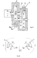
- Figure 1 is a principle drawing of the system for generating a linear force from rotation according the invention.
- Figure 2 illustrates the deformation of the working body /spring/ when it passes over the deforming surface.
- Figure 3 illustrates the deformation of the working body /solid cylindrical rod/ when it passes over the deforming surface.
- Figure 4 is a diagram showing the forming of an energy power field in a spring.
- Figure 5 is a diagram showing the creation of an energy power field in a solid.
- Figure 6 shows a variant of the working body rotation around point O .
- Figure 7 shows other variant of the working body rotation around point B .
- Figure 8 is a diagram of the velocities and forces formed of the mass action.
- Figure 9 is a diagram of the forces formed as a result of the elastic deformations.
- Figure 10 shows a variant of the working body having a variable cross section.
- Figure 11 shows another variant of the working body with a variable cross section.
- Figure 12 present a variant of the system shown on Fig.1, where the deforming forces applied on the working body are at strain direction.
- Figure 13 is a variant of the system shown on Fig.1. with changed axes of rotation and a variable cross section of the working body.
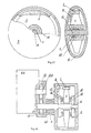
- Figure 14 is a variant of the system shown on Fig. 1, using a flywheel.
- Figure 15 is a variant of the system shown on Fig.1, with two working bodies.
- Figure 16 is a diagram of the forces at a rotating speed of the working body lower than the critical rotating speed and two working bodies of the system.
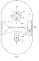
- Figure 17 is a variant of the system shown on Fig 1, including a disc-formed working body and specific drive mechanism.
- Figure 18 is a variant of the system shown on Fig.1 with two disc-formed working bodies.
- Figure 19 is a variant of the system shown on Fig.1 including two disc-formed working bodies deforming each other.
- Figure 20 is a principle drawing of a system for generating a linear force from rotation according to the invention including a working body formed as hollow discs.
- Figure 21 is a principle drawing of a system for generating a linear force from rotation according to the invention including a working body formed as hollow cylinders.
- the system for generating a linear force from rotation includes a cylindrical elastic or solid working body 1 with cross section S and length L . the ends of which freely slide in the caps 2 which also slide freely in the cylinder 3.
- On the outer side of the caps 2 are mounted the rollers 4 which roll on the inner surface of the cylindrical housing 6 on which is mounted the deforming surface 7.
- the deforming surface 7 can move along the circle of the cylindrical housing 6 and radially and can fix at a determined position about the housing 6 by means of a regulating device 8.
- the working deforming surface 7 is designed so that during their motion the rollers 4 move radially up to ⁇ L max at that the tension in the working body 1 is ⁇ ⁇ p where ⁇ p is the limit tension of proportionality where is valid the law of Huk.
- stator of the drive mechanism 5 and the housing 6 are fixed on the bearing frame 9.
- the same index can also be defined by the known from the technical literature method for its calculating.
- V E E/2m
- V E L C/2m
- the critical rotation speed Nk is a constant for a particular working body 1 and can be defined in advance as a function of its calculating length.
- Material of the working body E N/m 2 ⁇ kG/m 3 N k [rpm]
- L 1m
- L 0.5m
- Steel 2.10 11 7.8.10 3 11.10 3 22.10 3 11.10 4 22.10 4
- Bronze 0.9.10 11 8.5.10 3 9.10 3 18.10 3 9.10 4 18.10 4 Gold 1.2.10 11 19.3.10 3 5.10 3 10.10 3 5.10 4 10.10 4
- Formulas (27) and (28) are deducted for the specific profile of the deforming surface shown on fig.1. Naturally for other profile of the deforming surface 7 similar to that shown on fig.12 or fig.14 and also for other shape of the working body 1 for example as shown on fig. 10 or fig.17 the force F E will be defined in another way.
- K 2 2sin(N. ⁇ /N K .2) /here N is the working speed of rotation/.
- the working body 1 is fixed on the drive mechanism rotor which rotates by constant angle speed ⁇ .
- rollers 4 which roll on the inner surface of the cylindrical housing 6 so at each revolution of the working body 1 they pass over the contour of the deforming surface 7.
- the stator of the drive mechanism 5 and the cylindrical housing 6 are fixed on a bearing frame 9.
- the system shown on fig.13 includes a working body 1 with variable cross section which freely slides in the cylinder 3 which is fixed on the shaft 11 and the conic gear train 12, 13 and the rotor 10 of the drive mechanism 5 rotates by constant angle speed ⁇ .
- the rollers 4 that roll on the inner surface of the cylindrical housing which together with the stator of the drive mechanism 5 is fixed on the baring frame 9.
- the rollers 4 pass over the deforming surface 7 which by means of the regulating device 8 can move to radius direction and along the periphery of the cylindrical housing 6 and also to be fixed at a determined position.
- variable cross-section of the working body allows higher rotating speed, higher phase difference of the reactions and therefore higher efficiency of the system.
- the plane of rotation can be changed using the gear train 12, 13 and an optimal rotating speed N can be chosen.
- the regulating device 8 allows variation of the dimension and the direction of the acting force on the plane of rotation of the working body 1.
- the working body1 freely slides in the cylindrical opening 3 which is made directly in a flywheel 14.
- the flywheel 14 is fixed on the rotor 10 of the drive mechanism 5and rotates by constant angle speed ⁇ .
- the rollers 4 which roll on the inner surface of the cylindrical housing 6 and on each revolution of the working body 1 pass over the deforming surface 7.
- the stator of the drive mechanism 5 and the cylindrical housing 6 are fixed on the bearing frame 9.
- a regulating device 8 which can guarantee a possibility for motion of the deforming surface to radius direction and along the periphery of the cylindrical housing 6 and also to allow fixing of that surface 7 at a determined position.
- the working body 1 is disc shaped and is fixed on the rotor 10 of the drive mechanism 5 and rotates by constant angle speed ⁇ .
- the periphery of the working body 1 is deformed ceaselessly by the deforming surface 7 when the body rotates.
- the surface 7 can be moved radially and along the circle of the housing 6 and can be fixed at a determined position by means of the regulating device 8.
- the stator of the drive mechanism 5 is fixed on the axes shaped as a part of the housing 6.
- This embodiment has a simplified and lightened construction that allows higher rotating speed and therefore bigger phase difference of the reactions and respectively higher efficiency.
- the embodiment shown on fig.18 foresees the working body 1 to be shaped as metal disc which is fixed symmetrically with enough gap around the shaft 11 and is fastened by the rubber washers 16, 17 and the pressing nuts 18, 19.
- the disc 1 is rotated with constant angle speed ⁇ by the rotor 10 of the drive mechanism 5.
- the periphery slides on the inner cylindrical surface made in the housing 6, and is being deformed continuously passing over the deforming surface 7.
- surface 7 can move radially and along the circus of the cylindrical surface made in the housing 6 and to fix at a determined position.
- the torque is compensated which determine a stable orientation of the system during its motion.
- the disc shaped working body 1 is fixed on the shaft 11.
- This shaft can be moved along the axes Y in the groove 20 by means of the regulating device 8.
- the shaft stops at a fixed position whereas the axes of rotation keeps its orientation.
- Symmetrically about the axes X another working body 1 a is mounted which is fixed on the rotor 10 of the drive mechanism 5.
- the shaft 11 and the working body 1 are fixed at such position so that at the contact zone of the two working bodies 1 and 1 a an elastic deformation and a friction force are created such that the two bodies rotate by approximately equal but opposite angle speeds.
- That variant of the system has an extremely simple construction and constant direction of the propulsion force.
- the torque is compensated and the system is balanced as concerns the eccentricity.
- the resisting torque is little and can be reached high rotating speed and therefore high efficiency.
- the working body 1 one cane be made of a metal or non metal spring a solid of rubber, vulcanite, textolite, and other natural or synthetic materials or steel, bronze brass and other metals and alloys.
- the working body 1 can be made of composed materials from two or more solids.
- the working body 1 may have varied shape, for example, cylindrical shape with constant cross -section a shape with variable cross-section or disc shaped.
- Another embodiment of the system for generating a linear force includes elastic or solid working body 1 formed as at least two hollow discs placed parallel each other and crosswise to the axes of rotation.
- the two discs are joint so that they have a medial sector on which is mounted the bearing 4 so the inner ring of the bearing 4 is fixed on medial sector.
- the outer ring of the bearing 4 is fixed on the deforming device 25 that is mounted freely to the housing 3 of the system.
- the working body 1 is placed in the housing 6 so the outer central part of one of the discs of the working body is formed as a shaft rotating about the housing by means of the supporting bearing 2.
- the outer central part of the other disc is formed as an inlet shaft fixed on the rotor of the drive mechanism 5
- the system for generating a linear force from rotation includes a cylindrical elastic or solid body 1 made from five joint hollow cylinders. These cylinders have enough stout walls and are put in each other so they form two central units 26, 27, two medial units 28, 29 and one outer unit 30.
- the outer end of the central cylindrical unit 26 is fixed on the inner ring of bearing 22 whereas the outer ring of the bearing is fixed on the housing 6.
- the outer end of the central cylindrical unit 27 is fixed respectively to bearing 23 and the rotor 10 of the driving mechanism 5.
- a zone in the middle of the outer cylindrical unit 30 surface of the working body contacts the deforming device 25 which is mounted freely on the housing 6.
- a variant of the system includes a cylindrical elastic or solid body 1 which medial units are made from more than one joint cylinders put in each other thus elongating the path of the wave and phase difference.
Landscapes
- Engineering & Computer Science (AREA)
- Chemical & Material Sciences (AREA)
- Combustion & Propulsion (AREA)
- Mechanical Engineering (AREA)
- General Engineering & Computer Science (AREA)
- Pressure Welding/Diffusion-Bonding (AREA)
- Finish Polishing, Edge Sharpening, And Grinding By Specific Grinding Devices (AREA)
- General Electrical Machinery Utilizing Piezoelectricity, Electrostriction Or Magnetostriction (AREA)
- Transmission Devices (AREA)
- Retarders (AREA)
- Other Liquid Machine Or Engine Such As Wave Power Use (AREA)
Abstract
Description
- The present invention relates to a method and systems for generating a linear force from rotation and will find implementation in autonomous linear acceleration of any devices, transport vehicles, lifters and other mechanisms of the type called hereto an independent translation system.
- The presently known methods and systems for generating linear force from rotation can be classified depending on the used principle and the working body material as follows: electromagnetic, quantum, electronic, gravitational, impulsive, fluidic, gyroscopic /precession/, phase-frequency and eccentric-rotational. Actually the closest to the present invention are the designs from the last two groups - phase-frequency and eccentric-rotational. The phase-frequency methods and systems use rotation of at least two subsystems by different frequencies and a phase difference of the reaction forces is obtained. On the same principle are based the designs known from the published international application WO 89/10484 (PCT/FR89/00200) "PROPULSION METHOD AND ASSEMBLIES USING THE OSCILLATION OF FLEXIBLE BLADES ROTATINGLY DRIVEN IN A FORCE FIELD". That known designs use rotation of elements (r) at rotating speed Ω about a central axes while the elements rotate about other axes at speed ω. Due to the phase difference arising as a result of the law of action of masses along the blades which compose the flexible elements a propulsion force perpendicular to the centrifugal force of the rotation is generated.
- The disadvantages of that known solution consist in its complicated construction, little generated force as the forces are applied crosswise of the working bodies, low efficiency. To obtain the shown phase difference it needs revolution speed unattainable for the current technologies.
- On the same principle is based also the design known from RU No.2087746 "Method for generating active propulsion forces in changeable mechanical systems". The essence of that known design is as follows: in changeable mechanical systems at the mass center of each solid crosswise rotating outer circular forces are applied. These forces change cyclic their size together with the rotating speed of the system's solids following the law of harmonious asymmetrical oscillation about the axes of the resultant force. Arising in the system resisting torque from the system's solids rotation is determined by providing of a constant angle speed of rotation of the system's solids mass centers.
- The disadvantages of that design are complicated construction because of the sine forces generators availability, changeable angle speed which provoke grate dynamic loads, little phase difference because of the fact that the acting forces are applied crosswise to the working body which on its part determines obtaining little propulsion force. The asymmetry of the acting forces brings to grate dynamic tensions that are related to increase of the construction mechanical strength requirements
- In the eccentric-rotation methods and systems for getting traction is used the mass action of rotating and static solids at that the rotating center is asymmetric about the orbits which sometimes are complicated plane curves and in many cases spatial closed curved lines. The design known from RU No.2056524 "The gravitational engine of Savelkaev" is based on that principle. This engine has two solids with equal masses mounted on a common base allowing their simultaneous linear move from one to another position and also counter rotating motion. The linear and the rotating motions are done on the base plane by a driving device that is a crank-rocker mechanism
- The disadvantages of that known design are namely that grate dynamic tensions appear in certain points when the solids rotate along the above said complicated curves. Due to that grate dynamic loads the necessary revolutions can not be reached in order to get bigger phase difference and consequently bigger traction and efficiency. The method for the construction design and the construction itself are very sophisticated.
- On many design drawings are shown springs which however has secondary construction functions and are not used as basic working elements and respectively the genesis of the propulsion forces is not searched in the springs themselves or in the elasticity of the solids.
- DE 44 23 509 describes a method and a system for generating a linear force from rotation where a working body is fixed to a driving mechanism to rotates at constant rotating speed. At least at one point of the working body periphery is applied a force impulse, by passing over at least one deforming surface, deforming elastically the working body and directed radially.
- The main disadvantage of this known solution is that it can not provide for obtaining of a linear force sufficiantly grate for practical use.
- The aim of the present invention is to create a method and a system which guarantee generating of a grate practically usable directed force whereas the design of the system is simplified and the respective dynamic load in it to be commensurable with the obtained traction.
- The aim is reached by a method for generating a linear force from rotation where the working body rotates at constant rotating speed. The method is characterized in that at least at one point of the working body periphery a force impulse is applied deforming elastically the working body and directed radially. At that an energy power field is generated having length of the wave LE and speed VE that passes through the working body so at a point opposite to the point of the impulse application the working body transmits to the system a secondary impulse. The secondary impulse vector is turned up about the vector of the applied impulse at an angle different of 180° and the resultant force of the two impulses is the linear force.
- It is expediently that the working body rotates by rotating speed NK corresponding to the time for the energy power field motion through the working body Tk=
- It is appropriate the working body to rotate with speed N which is less than rotating speed Nk corresponding to the time Tk for the energy power field motion through the working body. Tk=
- In a preferred variant of the method at a point of the working body periphery on each its revolution in a determined zone and fixed period of time T several contiguous power impulses are applied. At that Ti<Tk/2, and Ti=Σti where ti is the time for applying of each particular impulse.
- In an other version of the method on each revolution of the working body impulses of deforming forces are applied consecutively at points of the working body periphery passing through a determined zone
- It is appropriate impulses of deforming forces to be applied at fixed points of the periphery of two or more working bodies on each revolution.
- It is also appropriate the deforming forces to be applied incessantly on the working body periphery.
- It is possible the deforming forces to be applied in direction of stress or strain of the working body.
- The aim is reached also by a system for generating a linear force from rotation including a working body mounted on a drive mechanism so that the working body rotates. The system is characterized in that the working body is elastic or solid and at a zone of the trajectory of the working body periphery at least one point passes over at least one deforming surface. When that point of the surface of the working body passes over the deforming surface a force impulse is generated deforming the working body and directed radially.
- In one variant of the system the ends of the working body are fitted in caps so that it can slide. Besides the working body together with the caps are fitted in a cylindrical body so that the caps slide freely in the cylindrical body which is fixed on the rotor of a drive mechanism. On the face surfaces of the caps are mounted rollers which roll over the inside surface of a cylindrical housing and to the housing at determined zone of the rollers trajectory at least one deforming surface is mounted.
- In another variant of the system the working body is fixed on the drive mechanism rotor and at the ends of the working body are mounted rollers. At that the working body is placed beside a cylindrical housing so that the rollers roll over the outer surface of the housing on a determined zone on which a deforming surface is formed.
- In other variant of the system the working body is placed in a cylindrical body which is fixed on the outlet shaft of a conic gear train the inlet shaft of which is the shaft of the drive mechanism. At the ends of the working body are mounted rollers so that they roll over the inner surface of a cylindrical housing in which the working body is placed and also the deforming surface is fixed on the housing.
- In other variant of the system the working body is placed in a cylindrical opening formed in a flywheel that is fixed on the drive mechanism rotor. At the ends of the working body are mounted rollers so they roll on the inner surface of a cylindrical housing in which the flywheel and the working body are placed whereas the deforming surface is fixed on the cylindrical housing.
- In other variant of embodiment the system includes two identical working bodies fixed on the shafts of the gear train so they rotate to different directions whereas one of the shafts is the outlet shaft of the drive mechanism. On the ends of each working body are mounted the respective rollers so that they roll over the cylindrical surfaces of the housing which forms two cylindrical chambers in one of which one working body is placed and in the other the second working body is placed. At that one shaft lays along the longitudinal axis of the first cylindrical chamber and the other lays along the longitudinal axes of the second cylindrical chamber of the housing. Besides two deforming surfaces are foreseen fixed on the respective cylindrical surfaces of both housing chambers.
- For these variants it is appropriate the deforming surface to be assembled on the housing with a possibility for radial movement and movement along the circus of the cylindrical housing and fixing at a determined position and to be provided with a regulating device.
- It is expediently the working body to be a solid or a cylindrical spring. It can be with a variable cross section that increases from the ends of the working body to its center of rotation.
- In another variant of the system the working body is formed as a disc whereas the deforming surface is mounted on the housing. The drive mechanism rotor is fixed on the working body and the stator of the drive mechanism is fixed on a shaft that is a part of the housing.
- In still other variant of the system the working body is a metallic disc fixed symmetrically with a gap on a shaft which is fixed on the drive mechanism rotor. The disc is fixed on the shaft by rubber washers and pressing nuts so that the outer periphery surface of the disc slides on the inner cylindrical surface of the housing on which is mounted the deforming surface.
- In the above variant it is appropriate the shaft to be an inlet shaft of a gear train on outlet shaft of which is mounted a second metallic disc by rubber washers and pressing nuts. At that the second disc is placed in a cylindrical housing on which inner cylindrical surface is mounted a second deforming surface.
- In other variant the system includes at least two disc-formed working bodies. At that one working body is fixed on a shaft which is mounted with a possibility for movement of the axes in a groove made in the housing and the other working body is mounted in the housing and fixed on the drive mechanism rotor. At that the first working body is fixed on a determined position about the second working body so in the contact zone of the two working bodies is created a deforming surface.
- It is appropriate the working body to be a hollow cylinder in which inner volume is filled fluid.
- Also it is possible the working body to be made from a composition of more than two materials.
- The system can include two or more deforming surfaces.
- When the working body is disc like it can be a gas-filled disc made of elastic material.
- The aim is also reached by a system for generating a linear force from rotation including a working body fixed on a drive mechanism so that the working body rotates. The system is characterized in that the working body is elastic or solid and is formed from at least two hollow discs joint each other by a medial sector and placed crosswise about the rotation axes. The working body is placed and rotates in a housing by means of bearings, besides to the inner side of the housing a deforming device is mounted so it presses or strains the medial section of the working body.
- In a variant of the system at the medial sector is mounted a bearing the inner rotating ring of which is fixed firmly to the medial sector and the outer ring is fixed on the deforming device.
- In other variant of the system the working body is made from more than two hollow disks. At that variant it is appropriate the hollow discs forming the working body to be even number.
- In other preferred variant of the system the deforming device is provided with a regulating device for change of the position and/or the length of the deforming device.
- The aim is also reached by a system for generating a linear force from rotation including a working body fixed on a driving mechanism so that the working body rotates. The system is characterized in that the working body is formed from at least one hollow cylinder which axes coincide with the axes of rotation. Besides a deforming device is mounted freely on the inner side of the housing so that it press or strain the middle of the outer cylindrical surface of the working body.
- Variant of the system includes a cylindrical elastic or solid body which medial units are made from more than one joint cylinders put in each other thus elongating the path of the wave and phase difference.
- The advantages of the method and system for generating a linear force from rotation consist in the simplified design by which in the different variants of embodiment of the system are generated big linear forces and respectively high efficiency. The possibilities for obtaining variable phase difference of the deforming force and the reaction by changing the position of the deforming surface are exceptionally useful for obtaining a different linear force regarding its dimension and direction.
- Figure 1 is a principle drawing of the system for generating a linear force from rotation according the invention.
- Figure 2 illustrates the deformation of the working body /spring/ when it passes over the deforming surface.
- Figure 3 illustrates the deformation of the working body /solid cylindrical rod/ when it passes over the deforming surface.
- Figure 4 is a diagram showing the forming of an energy power field in a spring.
- Figure 5 is a diagram showing the creation of an energy power field in a solid.
- Figure 6 shows a variant of the working body rotation around point O.
- Figure 7 shows other variant of the working body rotation around point B.
- Figure 8 is a diagram of the velocities and forces formed of the mass action.
- Figure 9 is a diagram of the forces formed as a result of the elastic deformations.
- Figure 10 shows a variant of the working body having a variable cross section.
- Figure 11 shows another variant of the working body with a variable cross section.
- Figure 12 present a variant of the system shown on Fig.1, where the deforming forces applied on the working body are at strain direction.
- Figure 13 is a variant of the system shown on Fig.1. with changed axes of rotation and a variable cross section of the working body.
- Figure 14 is a variant of the system shown on Fig. 1, using a flywheel.
- Figure 15 is a variant of the system shown on Fig.1, with two working bodies.
- Figure 16 is a diagram of the forces at a rotating speed of the working body lower than the critical rotating speed and two working bodies of the system.
- Figure 17 is a variant of the system shown on Fig 1, including a disc-formed working body and specific drive mechanism.
- Figure 18 is a variant of the system shown on Fig.1 with two disc-formed working bodies.
- Figure 19 is a variant of the system shown on Fig.1 including two disc-formed working bodies deforming each other.
- Figure 20 is a principle drawing of a system for generating a linear force from rotation according to the invention including a working body formed as hollow discs.
- Figure 21 is a principle drawing of a system for generating a linear force from rotation according to the invention including a working body formed as hollow cylinders.
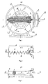
- The system for generating a linear force from rotation (fig.1) includes a cylindrical elastic or solid working body 1 with cross section S and length L. the ends of which freely slide in the caps 2 which also slide freely in the cylinder 3. The cylinder 3 is fixed on the rotor 10 of the drive mechanism 5. which rotates by constant angle speed Ω=constant. On the outer side of the caps 2 are mounted the rollers 4 which roll on the inner surface of the cylindrical housing 6 on which is mounted the deforming surface 7. The deforming surface 7 can move along the circle of the cylindrical housing 6 and radially and can fix at a determined position about the housing 6 by means of a regulating device 8. The working deforming surface 7 is designed so that during their motion the rollers 4 move radially up to ΔLmax at that the tension in the working body 1 is σ<σp where σp is the limit tension of proportionality where is valid the law of Huk.
- In this execution of the system the stator of the drive mechanism 5 and the housing 6 are fixed on the bearing frame 9.
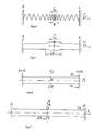
- Here down is revealed the essence of the method according to the invention. To motion one end A of the elastic working body 1 formed as a cylindrical spring (fig.2) or a solid working body (fig.3) at a distance ΔL to direction -X and getting back to direction +X or opposite a force impulse IF is necessary. At that ΔL is such that the tension due to the forces action in the working body 1 is σ<σp. As a result the system receives an impulse IA=-IF and an energy power field is created with length of the wave LE and velocity VE (see fig.4, fig.5). This field moves from point A to point B for time TK =
- In the same time while the field is moving the working body 1 turns about the axes Z around point O /fig.6/ or around point B /fig.7/ in the plain determined by the coordinates XY to an angel Θ=π or Θ=180° for the same time TK corresponding to a determined angle speed Ω K and rotating speed NK The force impulse at point B - IB becomes identical to the impulse IA at point A or IA+IB = IC ; IC ≠ 0; IC ≈ 2IE so the acceleration which the system will get is a=Ic/2πMc where Mc is the total mass of the system.
- The method for generating a linear force from rotation according the invention can be explained by the following theoretical calculations and conclusions:
- All the solids and the simple springs are characterized by elasticity in certain limits of deformations. If the deformation ΔL collinear to longitudinal axes of the working body 1 is such that the law of Huk is valid than the following equations can be written:
- ΔL[M]
- -absolute extension /contraction/ in linear meters
- L [M]
- -length of the working body 1 in linear meters
- ε
- -relative extension /contraction/
- σ[N/M2]
- -working tension in newtons on square meter
- E[N/M2]
- -module of elasticity in newtons on square meter
- F[N]
- -acting power in newtons
- C[N/M]
- -elastic index in newtons on meter
- From the above equations we define the elastic index of the solids:
- The elastic index C of a simple spring can be defined easily by loading the spring with different weights and its absolute extension /contraction/ is measured in the limits of the linear formula F=f(ΔL). The same index can also be defined by the known from the technical literature method for its calculating.
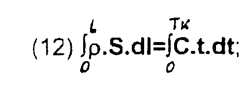
- When the end A of the working body moves to an infinitesimal distance dl << ΔL by speed V an infinitesimal mass dm is accelerated for that is necessary a force dF. On the other hand deforming the working body 1 by dl arises internal tension as consequence of the law of Huk and using for more simplicity the formula for the defined above elastic index and some basic concepts of the general mechanical theory we can write the equations:
- From the equations (2),(3),(4) and (5) we make the equations:
- After we integrate the left and the right parts of the equation (8) we get
- Using the equation (5) we come to the equations:
- We integrate in the respective limits
- m [kG] - the mass of the working body in kilograms
- Tk [s] - critical time in which the created power field front will move along the longitudinal axes of the working body 1 from point A to point B
-
- Using the equation (1) and (4) we write
- The speed by which the front of the power field moves along the length of the working body is:
- The equation (15) and (16) are basic for the present invention. The following conclusions can be done from them.
- 1. The time Tk does not depend on the dimension of the forces F and the impulses I which are applied.
- 2.The time Tk does not depend on the speed of action.
- 3.The time Tk does not depend on the cross section of the working body
- 4. The time Tk does not depend on the parameters of the power field.
- 5. For each particular body the time Tk is a constant and can be calculated as a function of its calculating length- TK = f(L).
-
- For obtaining the desired phase difference of the force impulses of the reactions IA and IB (fig2, 3) it is necessary the working body to be turned in time Tk to an angle Θ K = 180°; ΘK = π
- From the general theory for circular motion we write the equations
- Θ K - critical turning angle
- Ω K - critical angle speed - constant
- Nk [rpm] - critical rotating speed - constant.
-
- From the above equations it follows:
- In formula (21) and (22) is seen that the critical rotation speed Nk is a constant for a particular working body 1 and can be defined in advance as a function of its calculating length. The function Nk=f(L) concerning some materials is shown on table 1.
Material of the working body E N/m2 ρ kG/m3 Nk [rpm] L=10m L=5m L=1m L=0.5m Steel 2.1011 7.8.103 11.103 22.103 11.104 22.104 Bronze 0.9.1011 8.5.103 9.103 18.103 9.104 18.104 Gold 1.2.1011 19.3.103 5.103 10.103 5.104 10.104 Rubber 78.105 1.3.103 164 328 1640 3280 Vulcanite 258.105 1.4.103 287 575 2870 5750 - To define the resultant acting force of the system FC for convenience and clarity we resolve it into two forces FC=FM+FE and the relative impulses IC=IM +IE where:
- FM and IM are respectively the resultant force and impulse as a result of the mass motions
- FE and IE are respectively the resultant elastic force and impulse as a result of the deformation.
-
- To define IM and FM we proceed from the diagram shown on fig.8. On that diagram for a concrete chosen profile of the deforming surface 7 we follow the motion of the mass mi which is a part taken at random from the mass of all the rotating elements of the system /the working body and the other constructive details/. For the motion of the mass mi are valid the following equations:
- From the last equation we can write Imi=mi(Vi1-Vi2) = mi.ΔV1,2
- The function of the velocity V=f(Θ) interrupts at the meanings of Θ= -α and Θ = +α for that we integrate in separate intervals in which the function can be differentiated.
- As we have chosen a symmetrical profile of the deforming surface 7 and Ω = constant we can write that Vr1 = Vr2 /where Vr1 and Vr2 are respectively the velocities at time t1+ Δt and t2- Δt at that from the equation
- Diagonally opposite the mass ml motions along the circus with radius Ri whereas at the respective moments t3 and t4 the velocities are respectively Vi3 and Vi4 therefore ΔV3,4=Vi4-Vi3 .
- From the symmetry it follows that ΔV1,2 = -ΔV3,4 and therefore the resultant impulse Imi from the mass forces action in the two symmetrical intervals t1 - t2 and t3 - t4 is :
- The same conclusions are valid for the symmetrical intervals t5 - t6 and t7 - t8 and the respective mj and Rj so that Imj = 0.
- In addition to the above proof it is seen on fig.4 and fig.5 that due to the motion of the wave by speed VE the movement of the mass center of the working body 1 is along a closed curve as the body restores its initial form at an exactly fixed position on each revolution.
consequently: - From the diagram shown on fig.9 we determine IE , FE as follows:
- r - a variable radius; r = f()
- - a random angle
- - α - a fixed angle where the deformation force starts its action
- +α -an angle where the deformation force terminates its action
-
- From the equations:
- We define:
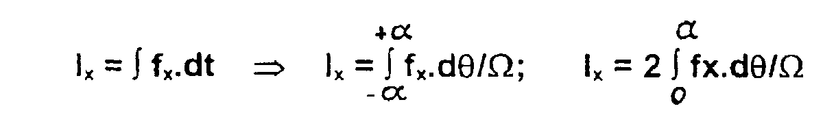
- After integrating it becomes
- From the same diagram shown on fig. it is seen that
- Formulas (27) and (28) are deducted for the specific profile of the deforming surface shown on fig.1. Naturally for other profile of the deforming surface 7 similar to that shown on fig.12 or fig.14 and also for other shape of the working body 1 for example as shown on fig. 10 or fig.17 the force FE will be defined in another way.
- In formulas (27) and (28) the following is not taken into consideration:
- bending of the energy power field and the dispersion of the forces along and at the transitional zones in the beginning and at the end of the deforming surface 7 /see fig. 9/;
- preliminary tensioning and deformation of the working body 1 and the construction as a result of the centrifugal forces;
- action of the reflected waves of the power field end the dispersion of the tensions in the construction of the system.
- After precise theoretical examinations not shown here and a range of practical measuring it was defined a coefficient K1 which takes into consideration the above mentioned reasons. The meanings of that coefficient are in the range 0.68 ÷ 0.83.
- Having in mind that the critical rotating speed NK due to design reasons may not be reached or N≠NK , is appropriate to use another coefficient K2 , which is calculated by the formula:
- Taking into consideration all the factors the dimension of the linear force /traction/ which is generated following the method and the system according to the present invention and which will push the system to a determined direction will be:
- The vector direction of this force is determined according the diagram shown on fig.16, where is the actually obtained angle of phase difference = N.π/NK
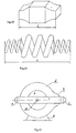
- On fig. 10 and 11 are shown two variants of execution of the working body 1 having a fillet central zone. Formed so the working body 1 can bear significantly grater strains without complicating the whole construction of the system. The specific shape of the solid working body on fig. 10 or of the spring on fig. 11 allows an even distribution of the tensions along the whole length and less deformation due to the action of the centrifugal forces.
- At the execution variant of the system shown on fig.12 the working body 1 is fixed on the drive mechanism rotor which rotates by constant angle speed Ω. At the ends of the working body 1 are mounted rollers 4 which roll on the inner surface of the cylindrical housing 6 so at each revolution of the working body 1 they pass over the contour of the deforming surface 7. The stator of the drive mechanism 5 and the cylindrical housing 6 are fixed on a bearing frame 9. The shown variant guarantee working body 1 under action of strain forces.
- The system shown on fig.13 includes a working body 1 with variable cross section which freely slides in the cylinder 3 which is fixed on the shaft 11 and the conic gear train 12, 13 and the rotor 10 of the drive mechanism 5 rotates by constant angle speed Ω. At the ends of the working body 1 are mounted the rollers 4 that roll on the inner surface of the cylindrical housing which together with the stator of the drive mechanism 5 is fixed on the baring frame 9. On each revolution of the working body 1 the rollers 4 pass over the deforming surface 7 which by means of the regulating device 8 can move to radius direction and along the periphery of the cylindrical housing 6 and also to be fixed at a determined position. At that embodiment of the system the variable cross-section of the working body allows higher rotating speed, higher phase difference of the reactions and therefore higher efficiency of the system. The plane of rotation can be changed using the gear train 12, 13 and an optimal rotating speed N can be chosen. The regulating device 8 allows variation of the dimension and the direction of the acting force on the plane of rotation of the working body 1.
- In the variant shown on fig.14 the working body1 freely slides in the cylindrical opening 3 which is made directly in a flywheel 14. The flywheel 14 is fixed on the rotor 10 of the drive mechanism 5and rotates by constant angle speed Ω. At the ends of the working body 1 are mounted the rollers 4 which roll on the inner surface of the cylindrical housing 6 and on each revolution of the working body 1 pass over the deforming surface 7. The stator of the drive mechanism 5 and the cylindrical housing 6 are fixed on the bearing frame 9. In that variant also is possible to be included a regulating device 8 which can guarantee a possibility for motion of the deforming surface to radius direction and along the periphery of the cylindrical housing 6 and also to allow fixing of that surface 7 at a determined position. By that variant is obtained simplification and lightening of the whole construction of the system whereas when the driving of the flywheel is done by a stationary drive mechanism can be obtained enginless motion for certain time.
- In the embodiment of the system shown on fig.15 are foreseen two identical working bodies 1, 1a which are fixed on the shafts 11, 11a and rotate to different directions by constant angle speeds +Ω and -Ω by means of the gear train 12. 13 and the rotor 10 of the drive mechanism 5. At the ends of the working bodies 1 and 1 a are mounted respectively the rollers 4 and 4a which roll on the cylindrical surfaces, formed in the housing 6. On each revolution of the working bodies 1 and 1 a the rollers 4,4a pass over the deforming surfaces 7, respectively 7a. By means of the regulating devices 8 and 8a the surfaces 7, 7a can move radially and along the periphery of the cylindrical surfaces of the housing 6 and can fix at a determined position. At that variant is obtained a constant direction of the resultant force vector not depending on the rotating speed (see fig.16). By suitable positioning of the deforming surfaces 7 and 7a is got rotation of the system to a desired direction. Thus motion and acceleration of the system along all the axes of a three-dimensional co-ordinate is obtained.
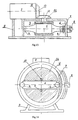
- In the embodiment shown on fig.17 the working body 1 is disc shaped and is fixed on the rotor 10 of the drive mechanism 5 and rotates by constant angle speed Ω. The periphery of the working body 1 is deformed ceaselessly by the deforming surface 7 when the body rotates. The surface 7 can be moved radially and along the circle of the housing 6 and can be fixed at a determined position by means of the regulating device 8.
- The stator of the drive mechanism 5 is fixed on the axes shaped as a part of the housing 6. This embodiment has a simplified and lightened construction that allows higher rotating speed and therefore bigger phase difference of the reactions and respectively higher efficiency.
- The embodiment shown on fig.18 foresees the working body 1 to be shaped as metal disc which is fixed symmetrically with enough gap around the shaft 11 and is fastened by the rubber washers 16, 17 and the pressing nuts 18, 19. The disc 1 is rotated with constant angle speed Ω by the rotor 10 of the drive mechanism 5. The periphery slides on the inner cylindrical surface made in the housing 6, and is being deformed continuously passing over the deforming surface 7. By means of the regulating device 8 that surface 7 can move radially and along the circus of the cylindrical surface made in the housing 6 and to fix at a determined position. The other end of the rotor 10 of the drive mechanism 5 by means of the gears 2 and 13 and the shaft 11 a rotates another working body 1 a placed in the housing 6a, which contains the same units and details as the housing 6. By this variant of the system is obtained easily a constant direction of the resultant force vector not depending on the rotating speed. Besides a grate propulsion force is obtained and by appropriate positioning of the deforming surface 7 is obtained rotation of the system to the desired direction so that is realized a possibility for motion and acceleration of the system along all the axes of three-dimensional co-ordinates.
- The torque is compensated which determine a stable orientation of the system during its motion.
- In the variant shown on fig.19, the disc shaped working body 1 is fixed on the shaft 11. This shaft can be moved along the axes Y in the groove 20 by means of the regulating device 8. The shaft stops at a fixed position whereas the axes of rotation keeps its orientation. Symmetrically about the axes X another working body 1 a is mounted which is fixed on the rotor 10 of the drive mechanism 5. The shaft 11 and the working body 1 are fixed at such position so that at the contact zone of the two working bodies 1 and 1 a an elastic deformation and a friction force are created such that the two bodies rotate by approximately equal but opposite angle speeds. That variant of the system has an extremely simple construction and constant direction of the propulsion force. The torque is compensated and the system is balanced as concerns the eccentricity. The resisting torque is little and can be reached high rotating speed and therefore high efficiency.
- As it was described in connection with the different execution variants of the system illustrated on the attached figures the working body 1 one cane be made of a metal or non metal spring a solid of rubber, vulcanite, textolite, and other natural or synthetic materials or steel, bronze brass and other metals and alloys. The working body 1 can be made of composed materials from two or more solids.
- The working body 1 may have varied shape, for example, cylindrical shape with constant cross -section a shape with variable cross-section or disc shaped.
- Another embodiment of the system for generating a linear force (fig.20) includes elastic or solid working body 1 formed as at least two hollow discs placed parallel each other and crosswise to the axes of rotation. The two discs are joint so that they have a medial sector on which is mounted the bearing 4 so the inner ring of the bearing 4 is fixed on medial sector. The outer ring of the bearing 4 is fixed on the deforming device 25 that is mounted freely to the housing 3 of the system. The working body 1 is placed in the housing 6 so the outer central part of one of the discs of the working body is formed as a shaft rotating about the housing by means of the supporting bearing 2. The outer central part of the other disc is formed as an inlet shaft fixed on the rotor of the drive mechanism 5
- The performance of this system for generating a linear force from rotation is as follows:
- When the working body 1 is rotated by the drive mechanism 5 at the medial sector between the two discs of the working body 1 is applied a deforming force at strain or stress by the deforming device 25. That force is applied consequently and continuously over different cross-sections of the medial sector due to the rotation of the working body 1. The primary force of reaction equal and opposite to the applied deforming force is transmitted through the deforming device 25 to the housing of the system. Under the action of the deforming force the walls of the discs which must be enough stout periodically are exerted by different tensions /at strain. stress. yield torsion and others/ corresponding to the rotating speed of the working body and the deforming impulses. As a result to the bearings 2 and from there to the housing 3 are transmitted secondary reaction forces. As the exertion of the disc's walls is done in a fixed period of time so the secondary reaction forces are not collinear to the primary reaction force. Consequently a resultant force that is different from zero is generated therefore the rotation is transformed into a linear force. Changing the disposition and the length of the deforming device 25 can be changed the direction and dimension of the generated linear force.
- In a further embodiment the system for generating a linear force from rotation (fig.21) includes a cylindrical elastic or solid body 1 made from five joint hollow cylinders. These cylinders have enough stout walls and are put in each other so they form two central units 26, 27, two medial units 28, 29 and one outer unit 30. The outer end of the central cylindrical unit 26 is fixed on the inner ring of bearing 22 whereas the outer ring of the bearing is fixed on the housing 6. The outer end of the central cylindrical unit 27 is fixed respectively to bearing 23 and the rotor 10 of the driving mechanism 5. A zone in the middle of the outer cylindrical unit 30 surface of the working body contacts the deforming device 25 which is mounted freely on the housing 6.
- The action of this embodiment of the system is as follows: (see fig 21). After driving of the working body 1 by the driving mechanism 5, force impulses are applied by the deforming device 25 at the middle zone of the outer cylindrical surface. The force impulses are applied consequently and continuously. The primary reaction force corresponding to the applied impulses is transmitted through the deforming device 25 to the housing 6 of the system. Under action of the deforming force impulses the walls of the cylinders which must be enough stout are strained periodically in accordance with the rotating speed of the working body 1 and the deforming force impulses. As a certain time for the field wave passing through the cylinders walls is necessary, then the secondary reaction forces at bearing 22. 23 will not be collinear to the primary reaction force. Therefore a resultant propulsion force different of zero is generated. By changing the deforming device 25 position can be changed the direction and the dimension of the generated force.
- A variant of the system includes a cylindrical elastic or solid body 1 which medial units are made from more than one joint cylinders put in each other thus elongating the path of the wave and phase difference.
Claims (31)
- A method for generating a linear force from a rotation within a system comprising a working body (1) fixed to a driving mechanism (5), where the working body (1) rotates at constant rotating speed wherein to at least at one point of the working body periphery is applied a force impulse deforming elastically the working body (1) and directed radially, characterized in that an energy power field having wave length LE and speed VE is generated which passes through the working body (1) so that at a point opposite to the point of the impulse application the working body (1) transmits to the system a secondary impulse with a vector turned towards the reaction of the applied impulse vector to an angle different of 180° therefore the resultant force from the two impulses is the linear force.
- A method in accordance with claim 1, characterized in that the energy power field passes through the working body (1) for a fixed time TK=√2m/C, where m is the mass of the working body (1), C is the elastic index of the working body (1) to which time corresponds a determined speed of rotation NK, whereas the reaction forces become unidirectional.
- A method in accordance with claim 1 characterized, in that the energy power field passes through the working body (1) for a fixed time TK=√2m/C, where m is the mass of the working body (1), C is the elastic index of the working body (1) whereas the rotating speed N of the working body (1) is less than the rotating speed NK corresponding to TK therefore the vector of the secondary impulse is rotated to an angle Θ=πN/NK, and the dimension of the linear force is corrected by a coefficient K2=2sin(N.π/NK.2).
- A method in accordance with claims 1, 2 and 3, characterized in that at a point of the working body periphery during each revolution at a predetermined zone in a fixed period of time Ti several consequent force impulses are applied, where Ti<TK/2, and Ti=∑ti where ti is the time for action of each separate impulse.
- A method in accordance with one of the claims 1 to 4, characterized in that on each working body revolution deforming force impulses are applied consequently at points of the working body periphery passing consequently through a predetermined zone.
- A method in accordance with one of the claims 1 to 5, characterized in that on each revolution deforming force impulses are applied at predetermined periphery points of two or more working bodies (1), (1a).
- A method in accordance with one of the claims 1 to 5, characterized in that the deforming forces are applied continuously at the periphery of the working body (1).
- A method in accordance with one of the claims 1 to 6, characterized in that the deforming forces are applied at stress direction of the working body (1).
- A method in accordance with one of the claims 1 to 6, characterized in that the deforming forces are applied at strain direction of the working body (1).
- A system for generating a linear force from rotation including a working body (1) fixed to a driving mechanism (5) so that the working body (1) rotates wherein the working body (1) is elastic or solid and at a zone of the trajectory of the working body periphery at least one point passes over at least one deforming surface (7) as a result a force impulse is generated deforming the working body (1) and directed radially, characterized in that an energy power field having wave length LE and speed VE is generated which passes through the working body (1) so that at a point opposite to the point of the impulse application the working body (1) transmits to the system a secondary impulse with a vector turned towards the reaction of the applied impulse vector to an angle different of 180° therefore the resultant force from the two impulses is the linear force.
- A system in accordance with claim 10, characterized in that the ends of the working body (1) freely slide in the caps (2) whereas the working body (1) together with the caps (2) are placed in the cylindrical body (3) so that the caps (2) freely slide in the cylindrical body (3) which is coupled with the rotor (10) of the driving mechanism (5) at that on the outer surface of the caps (2) are mounted the rollers (4) which roll over the inner surface of the cylindrical housing (6) and at least one deforming surface (7) is mounted to the housing (6) at a predetermined zone of the rollers (4) path.
- A system in accordance with claim 10, characterized in that the working body (1) is coupled with the rotor (10) of the driving mechanism (5) and at the ends of the working body (1) are mounted rollers (4) whereas the working body (1) is placed beside the cylindrical housing (6) so that the rollers (4) roll over the outer surface of the housing (6) to wich a deforming surface (7) is formed at an predetermined zone.
- A system in accordance with claim 10, characterized in that the working body (1) is placed in a cylindrical body (3) coupled with the outlet shaft (11) of the cone gear (12), (13) the inlet shaft of which is the shaft of the driving mechanism (5) and at the ends of the working body (1) are mounted the rollers (4) so that they roll over the inner surface of the cylindrical housing (6) in which is placed the working body (1) whereas the deforming surface (7) is mounted to the housing (6).
- A system in accordance with claim 10, characterized in that the working body (1) is placed in a cylindrical opening formed in a flywheel (14) which is coupled with the rotor (10) of the driving mechanism (5) whereas at the ends of the working body (1) are mounted the rollers (4) so they roll over the inner surface of the cylindrical housing (6) in which are placed the flywheel (14) and the working body and the deforming surface (7) is mounted to the cylindrical housing (6).
- A system in accordance with claim 10, characterized in that the system includes two identical working bodies (1), (1a), coupled with the shafts (11), (11a) of the gear (12), (13) so they rotate to different directions, at that one shaft (11a) is an outlet shaft of the driving mechanism (5), and at the ends of each working body (1), (1a) the rollers (4), (4a) are mounted respectively so they roll over the cylindrical surfaces of the housing (6) which forms two cylindrical chambers in one of which the working body (1) together with the gear (12), (13) is placed and in the other the second working body (1 a) is placed whereas the shaft (11) lay on the longitudinal axes of the first cylindrical chamber, and the shaft (11 a) lay on the longitudinal axes of the second cylindrical chamber of the housing (6) besides two deforming surfaces (7), (7a) mounted to the respective cylindrical surfaces of both chambers of the housing (6) are provided.
- A system in accordance with one of claims 10 to 15, characterized in that the deforming surface (7) is mounted to the housing (6) with possibilities for radial moving and motion along the circle of the cylindrical housing (6) and fixing at a determined position and is equipped with a regulating device (8).
- A system in accordance with one of claims 10 to 16, characterized in that the working body (1) is solid.
- A system in accordance with one of claims 10 to 16, characterized in that the working body (1) is a cylindrical spring.
- A system in accordance with one of claims 10 to 18, characterized in that the working body (1) has a variable cross-section that increases from the ends of the working body (1) towards the center of its rotation.
- A system in accordance with claim 10, characterized in that the working body (1) is disc shaped and the deforming surface (7) is mounted to the housing (6) whereas the rotor (10) of the driving mechanism (5) is coupled with the working body (1) and the stator of the driving mechanism (5) is fixed to the axes (15) which forms part of the housing (6).
- A system in accordance with claim 10, characterized in that the working body (1) is a metal disc fixed symmetrically with a gap to the shaft (11) which is coupled with the rotor (10) of the drive mechanism (5), whereas the disc (1) is fixed to the shaft (11) by rubber washers (16), (17) and fastening nuts (18), (19), so that the outer peripheral surface of the disc slides over the inner cylindrical surface of the housing (6) to which the deforming surface (7) is mounted.
- A system in accordance with claim 21, characterized in that the shaft (11) is an inlet shaft of the gear (12), (13) to which outlet shaft (11 a) is mounted a second metal disc by the rubber washers (16a), (17a) and fastening nuts (18a), (19a) whereas the second disc is placed in the cylindrical housing (6a) to which inner cylindrical surface the second deforming surface (7a) is mounted.
- A system in accordance with claim 10, characterized in that the system includes at least two disc shaped working bodies (1), (1a) where the working body (1) is coupled with the shaft (11) which is mounted so that its axes can move in a grove (20) formed in the housing (6) and the other working body (1a) is mounted in the housing (6) and is coupled with the rotor (10) of the driving mechanism (5) whereas the first working body (1) is fixed at a special position towards the second working body (1a) so that at the contact zone of the two working bodies (1), (1a) a deforming surface (7) (7a) is formed.
- A system in accordance with claims 10, 11, 12, 13, 14 or 15, characterized in that the working body (1) is a hollow cylinder (3) filled inside with a fluid.
- A system in accordance with one of claims 10 to 24, characterized in that the system includes two or more deforming surfaces (7), (7a).
- A system in accordance with claims 20 or 23, characterized in that the working body (1) is a gas filled disc made from elastic material.
- A system in accordance with one of claims 10 to 26, characterized in that the working body (1) is composite made from two or more solid materials.
- A system in accordance with claim 10, characterized in that the solid or elastic working body (1) coupled with the driving mechanism (5) is formed of at least two hollow discs joint to each other by a medial zone and placed crosswise towards the rotating axes where the working body (1) is placed in the housing (6) and rotates towards the housing (6) by means of bearings (22) and to the inner side of the housing (6) at least one deforming device (25) is mounted so that it presses or strains the zone in the middle of the two discs of the working body (1).
- A system in accordance with claim 28, characterized in that the working body (1) is formed of more than two hollow discs.
- A system in accordance with claim 10, characterized in that the solid or elastic working body (1) coupled with the driving mechanism (5) is made of at least two hollow joint cylinders (3) put in each other and laying along the axes of rotation so they form central medial and outer units (26), (27), (28), (29), (30) whereas one central unit (26) is fixed to a bearing and another to the driving mechanism (5) and the middle zone of the outer unit (30) contracts at least one deforming device (25) which is mounted freely to the housing (6).
- A system in accordance with claim 30, characterized in that the system includes at least two working bodies (1) joint by a medial zone which contacts the deforming device (25) whereas the outer end of one of the bodies is fixed to a bearing (22) and the outer end of the other body is coupled with the driving mechanism (5).
Applications Claiming Priority (5)
| Application Number | Priority Date | Filing Date | Title |
|---|---|---|---|
| BG103410A BG63735B1 (en) | 1999-05-18 | 1999-05-18 | Method and system for producing directive force from rotation |
| BG10341099 | 1999-05-18 | ||
| BG10375299 | 1999-09-24 | ||
| BG103752A BG103752A (en) | 1999-09-24 | 1999-09-24 | System for obtaining a directed force as a result or rotation |
| PCT/BG2000/000014 WO2000073653A2 (en) | 1999-05-18 | 2000-05-15 | Method and system for generating a linear force from rotation |
Publications (2)
| Publication Number | Publication Date |
|---|---|
| EP1179138A2 EP1179138A2 (en) | 2002-02-13 |
| EP1179138B1 true EP1179138B1 (en) | 2004-02-11 |
Family
ID=25663374
Family Applications (1)
| Application Number | Title | Priority Date | Filing Date |
|---|---|---|---|
| EP00924991A Expired - Lifetime EP1179138B1 (en) | 1999-05-18 | 2000-05-15 | Method and system for generating a linear force from rotation |
Country Status (5)
| Country | Link |
|---|---|
| EP (1) | EP1179138B1 (en) |
| AT (1) | ATE259468T1 (en) |
| AU (1) | AU4387400A (en) |
| DE (1) | DE60008236T2 (en) |
| WO (1) | WO2000073653A2 (en) |
Family Cites Families (4)
| Publication number | Priority date | Publication date | Assignee | Title |
|---|---|---|---|---|
| US4744259A (en) * | 1987-06-05 | 1988-05-17 | Peterson Oscar F A | Apparatus for producing a directional unit force |
| FR2630784B1 (en) * | 1988-04-27 | 1990-08-31 | Minard Joel | PROPULSION METHOD AND ASSEMBLY USING THE OSCILLATION OF FLEXIBLE BLADES DRIVEN IN ROTATION IN A FORCE FIELD |
| US5388470A (en) * | 1993-06-28 | 1995-02-14 | Marsh, Jr.; Richard O. | Centrifugal force drive machine |
| DE4423509A1 (en) * | 1994-07-05 | 1995-03-16 | Roland Kruk | Principle which indicates how the energy stored in an accelerated circular motion can be re-stored into a translatory motion, and a drive resulting therefrom for space vehicles |
-
2000
- 2000-05-15 AT AT00924991T patent/ATE259468T1/en not_active IP Right Cessation
- 2000-05-15 AU AU43874/00A patent/AU4387400A/en not_active Abandoned
- 2000-05-15 DE DE60008236T patent/DE60008236T2/en not_active Expired - Fee Related
- 2000-05-15 EP EP00924991A patent/EP1179138B1/en not_active Expired - Lifetime
- 2000-05-15 WO PCT/BG2000/000014 patent/WO2000073653A2/en not_active Ceased
Also Published As
| Publication number | Publication date |
|---|---|
| AU4387400A (en) | 2000-12-18 |
| EP1179138A2 (en) | 2002-02-13 |
| WO2000073653B1 (en) | 2001-06-14 |
| WO2000073653A2 (en) | 2000-12-07 |
| DE60008236D1 (en) | 2004-03-18 |
| ATE259468T1 (en) | 2004-02-15 |
| WO2000073653A3 (en) | 2001-04-12 |
| DE60008236T2 (en) | 2004-12-02 |
Similar Documents
| Publication | Publication Date | Title |
|---|---|---|
| US5068565A (en) | Motor conversion mechanism utilizing elastic action | |
| Ericson et al. | Experimental measurement of the effects of torque on the dynamic behavior and system parameters of planetary gears | |
| US5241235A (en) | Twisting actuators | |
| US9927005B2 (en) | Two-stage hypocycloidal gear train | |
| KR101433573B1 (en) | Gear device | |
| KR101555796B1 (en) | Energy generator | |
| US20220252140A1 (en) | Coaxial gear set | |
| EP1179138B1 (en) | Method and system for generating a linear force from rotation | |
| JPH06121561A (en) | Ultrasonic motor | |
| US5443428A (en) | Gearless mechanical transmission | |
| US6429576B1 (en) | Centrifugal impulse piezoelectric electrical generator | |
| WO1997026702A1 (en) | Motor | |
| US20080060460A1 (en) | Propulsion device employing conversion of rotary motion into a unidirectional linear force | |
| US4608875A (en) | Inertial transmission | |
| RU2177834C2 (en) | Block bearing for machines performing nutation motion | |
| WO2007084090A1 (en) | Method of generating coriolis's levitation forces and a gyroscopic system ('gyro-turbine') | |
| EP4531264A1 (en) | High power piezoelectric motor and drive | |
| JP7622976B2 (en) | Positive and reverse fine rotation elastic bearing | |
| JP2023002890A (en) | Speed reduction mechanism | |
| AU725082B2 (en) | Support bearing for nutating machines | |
| RU2124143C1 (en) | Inertia engine | |
| JP2016197946A (en) | Ultrasonic actuator | |
| RU2263241C2 (en) | Method of synchronous rotating of spherical bodies | |
| US11621655B1 (en) | Piezoelectric motor and generator | |
| JPH09219979A (en) | Vibration actuator |
Legal Events
| Date | Code | Title | Description |
|---|---|---|---|
| PUAI | Public reference made under article 153(3) epc to a published international application that has entered the european phase |
Free format text: ORIGINAL CODE: 0009012 |
|
| 17P | Request for examination filed |
Effective date: 20011213 |
|
| AK | Designated contracting states |
Kind code of ref document: A2 Designated state(s): AT BE CH CY DE DK ES FI FR GB GR IE IT LI LU MC NL PT SE |
|
| AX | Request for extension of the european patent |
Free format text: AL PAYMENT 20011213;LT PAYMENT 20011213;LV PAYMENT 20011213;MK PAYMENT 20011213;RO PAYMENT 20011213;SI PAYMENT 20011213 |
|
| 17Q | First examination report despatched |
Effective date: 20030326 |
|
| GRAH | Despatch of communication of intention to grant a patent |
Free format text: ORIGINAL CODE: EPIDOS IGRA |
|
| GRAS | Grant fee paid |
Free format text: ORIGINAL CODE: EPIDOSNIGR3 |
|
| GRAA | (expected) grant |
Free format text: ORIGINAL CODE: 0009210 |
|
| AK | Designated contracting states |
Kind code of ref document: B1 Designated state(s): AT BE CH CY DE DK ES FI FR GB GR IE IT LI LU MC NL PT SE |
|
| AX | Request for extension of the european patent |
Extension state: AL LT LV MK RO SI |
|
| PG25 | Lapsed in a contracting state [announced via postgrant information from national office to epo] |
Ref country code: NL Free format text: LAPSE BECAUSE OF FAILURE TO SUBMIT A TRANSLATION OF THE DESCRIPTION OR TO PAY THE FEE WITHIN THE PRESCRIBED TIME-LIMIT Effective date: 20040211 Ref country code: LI Free format text: LAPSE BECAUSE OF FAILURE TO SUBMIT A TRANSLATION OF THE DESCRIPTION OR TO PAY THE FEE WITHIN THE PRESCRIBED TIME-LIMIT Effective date: 20040211 Ref country code: IT Free format text: LAPSE BECAUSE OF FAILURE TO SUBMIT A TRANSLATION OF THE DESCRIPTION OR TO PAY THE FEE WITHIN THE PRESCRIBED TIME-LIMIT;WARNING: LAPSES OF ITALIAN PATENTS WITH EFFECTIVE DATE BEFORE 2007 MAY HAVE OCCURRED AT ANY TIME BEFORE 2007. THE CORRECT EFFECTIVE DATE MAY BE DIFFERENT FROM THE ONE RECORDED. Effective date: 20040211 Ref country code: FI Free format text: LAPSE BECAUSE OF FAILURE TO SUBMIT A TRANSLATION OF THE DESCRIPTION OR TO PAY THE FEE WITHIN THE PRESCRIBED TIME-LIMIT Effective date: 20040211 Ref country code: CY Free format text: LAPSE BECAUSE OF FAILURE TO SUBMIT A TRANSLATION OF THE DESCRIPTION OR TO PAY THE FEE WITHIN THE PRESCRIBED TIME-LIMIT Effective date: 20040211 Ref country code: CH Free format text: LAPSE BECAUSE OF FAILURE TO SUBMIT A TRANSLATION OF THE DESCRIPTION OR TO PAY THE FEE WITHIN THE PRESCRIBED TIME-LIMIT Effective date: 20040211 Ref country code: BE Free format text: LAPSE BECAUSE OF FAILURE TO SUBMIT A TRANSLATION OF THE DESCRIPTION OR TO PAY THE FEE WITHIN THE PRESCRIBED TIME-LIMIT Effective date: 20040211 Ref country code: AT Free format text: LAPSE BECAUSE OF FAILURE TO SUBMIT A TRANSLATION OF THE DESCRIPTION OR TO PAY THE FEE WITHIN THE PRESCRIBED TIME-LIMIT Effective date: 20040211 |
|
| REG | Reference to a national code |
Ref country code: GB Ref legal event code: FG4D |
|
| REG | Reference to a national code |
Ref country code: CH Ref legal event code: EP |
|
| REG | Reference to a national code |
Ref country code: IE Ref legal event code: FG4D |
|
| REF | Corresponds to: |
Ref document number: 60008236 Country of ref document: DE Date of ref document: 20040318 Kind code of ref document: P |
|
| PGFP | Annual fee paid to national office [announced via postgrant information from national office to epo] |
Ref country code: GB Payment date: 20040427 Year of fee payment: 5 |
|
| PG25 | Lapsed in a contracting state [announced via postgrant information from national office to epo] |
Ref country code: SE Free format text: LAPSE BECAUSE OF FAILURE TO SUBMIT A TRANSLATION OF THE DESCRIPTION OR TO PAY THE FEE WITHIN THE PRESCRIBED TIME-LIMIT Effective date: 20040511 Ref country code: GR Free format text: LAPSE BECAUSE OF FAILURE TO SUBMIT A TRANSLATION OF THE DESCRIPTION OR TO PAY THE FEE WITHIN THE PRESCRIBED TIME-LIMIT Effective date: 20040511 Ref country code: DK Free format text: LAPSE BECAUSE OF FAILURE TO SUBMIT A TRANSLATION OF THE DESCRIPTION OR TO PAY THE FEE WITHIN THE PRESCRIBED TIME-LIMIT Effective date: 20040511 |
|
| PG25 | Lapsed in a contracting state [announced via postgrant information from national office to epo] |
Ref country code: LU Free format text: LAPSE BECAUSE OF NON-PAYMENT OF DUE FEES Effective date: 20040515 |
|
| PG25 | Lapsed in a contracting state [announced via postgrant information from national office to epo] |
Ref country code: IE Free format text: LAPSE BECAUSE OF NON-PAYMENT OF DUE FEES Effective date: 20040517 |
|
| PG25 | Lapsed in a contracting state [announced via postgrant information from national office to epo] |
Ref country code: ES Free format text: LAPSE BECAUSE OF FAILURE TO SUBMIT A TRANSLATION OF THE DESCRIPTION OR TO PAY THE FEE WITHIN THE PRESCRIBED TIME-LIMIT Effective date: 20040522 |
|
| PG25 | Lapsed in a contracting state [announced via postgrant information from national office to epo] |
Ref country code: MC Free format text: LAPSE BECAUSE OF NON-PAYMENT OF DUE FEES Effective date: 20040531 |
|
| LTIE | Lt: invalidation of european patent or patent extension |
Effective date: 20040211 |
|
| NLV1 | Nl: lapsed or annulled due to failure to fulfill the requirements of art. 29p and 29m of the patents act | ||
| REG | Reference to a national code |
Ref country code: CH Ref legal event code: PL |
|
| ET | Fr: translation filed | ||
| PLBE | No opposition filed within time limit |
Free format text: ORIGINAL CODE: 0009261 |
|
| STAA | Information on the status of an ep patent application or granted ep patent |
Free format text: STATUS: NO OPPOSITION FILED WITHIN TIME LIMIT |
|
| 26N | No opposition filed |
Effective date: 20041112 |
|
| REG | Reference to a national code |
Ref country code: IE Ref legal event code: MM4A |
|
| PGFP | Annual fee paid to national office [announced via postgrant information from national office to epo] |
Ref country code: DE Payment date: 20050420 Year of fee payment: 6 |
|
| PG25 | Lapsed in a contracting state [announced via postgrant information from national office to epo] |
Ref country code: GB Free format text: LAPSE BECAUSE OF NON-PAYMENT OF DUE FEES Effective date: 20050515 |
|
| PGFP | Annual fee paid to national office [announced via postgrant information from national office to epo] |
Ref country code: FR Payment date: 20050525 Year of fee payment: 6 |
|
| GBPC | Gb: european patent ceased through non-payment of renewal fee |
Effective date: 20050515 |
|
| PG25 | Lapsed in a contracting state [announced via postgrant information from national office to epo] |
Ref country code: DE Free format text: LAPSE BECAUSE OF NON-PAYMENT OF DUE FEES Effective date: 20061201 |
|
| REG | Reference to a national code |
Ref country code: FR Ref legal event code: ST Effective date: 20070131 |
|
| PG25 | Lapsed in a contracting state [announced via postgrant information from national office to epo] |
Ref country code: PT Free format text: LAPSE BECAUSE OF NON-PAYMENT OF DUE FEES Effective date: 20040711 |
|
| PG25 | Lapsed in a contracting state [announced via postgrant information from national office to epo] |
Ref country code: FR Free format text: LAPSE BECAUSE OF NON-PAYMENT OF DUE FEES Effective date: 20060531 |