EP1179133B1 - Switch gauge - Google Patents
Switch gauge Download PDFInfo
- Publication number
- EP1179133B1 EP1179133B1 EP00932212A EP00932212A EP1179133B1 EP 1179133 B1 EP1179133 B1 EP 1179133B1 EP 00932212 A EP00932212 A EP 00932212A EP 00932212 A EP00932212 A EP 00932212A EP 1179133 B1 EP1179133 B1 EP 1179133B1
- Authority
- EP
- European Patent Office
- Prior art keywords
- switch
- lockpin
- assembly
- air filter
- indicating device
- Prior art date
- Legal status (The legal status is an assumption and is not a legal conclusion. Google has not performed a legal analysis and makes no representation as to the accuracy of the status listed.)
- Expired - Lifetime
Links
Images


Classifications
-
- B—PERFORMING OPERATIONS; TRANSPORTING
- B01—PHYSICAL OR CHEMICAL PROCESSES OR APPARATUS IN GENERAL
- B01D—SEPARATION
- B01D46/00—Filters or filtering processes specially modified for separating dispersed particles from gases or vapours
- B01D46/0084—Filters or filtering processes specially modified for separating dispersed particles from gases or vapours provided with safety means
- B01D46/0086—Filter condition indicators
-
- F—MECHANICAL ENGINEERING; LIGHTING; HEATING; WEAPONS; BLASTING
- F02—COMBUSTION ENGINES; HOT-GAS OR COMBUSTION-PRODUCT ENGINE PLANTS
- F02M—SUPPLYING COMBUSTION ENGINES IN GENERAL WITH COMBUSTIBLE MIXTURES OR CONSTITUENTS THEREOF
- F02M35/00—Combustion-air cleaners, air intakes, intake silencers, or induction systems specially adapted for, or arranged on, internal-combustion engines
- F02M35/02—Air cleaners
- F02M35/08—Air cleaners with means for removing dust, particles or liquids from cleaners; with means for indicating clogging; with by-pass means; Regeneration of cleaners
- F02M35/09—Clogging indicators ; Diagnosis or testing of air cleaners
-
- B—PERFORMING OPERATIONS; TRANSPORTING
- B01—PHYSICAL OR CHEMICAL PROCESSES OR APPARATUS IN GENERAL
- B01D—SEPARATION
- B01D2279/00—Filters adapted for separating dispersed particles from gases or vapours specially modified for specific uses
- B01D2279/60—Filters adapted for separating dispersed particles from gases or vapours specially modified for specific uses for the intake of internal combustion engines or turbines
-
- Y—GENERAL TAGGING OF NEW TECHNOLOGICAL DEVELOPMENTS; GENERAL TAGGING OF CROSS-SECTIONAL TECHNOLOGIES SPANNING OVER SEVERAL SECTIONS OF THE IPC; TECHNICAL SUBJECTS COVERED BY FORMER USPC CROSS-REFERENCE ART COLLECTIONS [XRACs] AND DIGESTS
- Y10—TECHNICAL SUBJECTS COVERED BY FORMER USPC
- Y10S—TECHNICAL SUBJECTS COVERED BY FORMER USPC CROSS-REFERENCE ART COLLECTIONS [XRACs] AND DIGESTS
- Y10S116/00—Signals and indicators
- Y10S116/25—Air filter condition indicator
Definitions
- the present invention relates generally to a mechanical filter gauge for determining the filtering capability of a vehicle filter, and in particular to a mechanical gauge for measuring and displaying the functionality of a vehicle's air filter.
- the improved device of the present invention is used in connection with an air filter for internal combustion engines. It is particularly useful for application to turbocharged diesel engines on trucks, tractors and industrial and marine applications.
- the device indicates and locks itself in position, and activates a signaling device on the vehicle dashboard, when the air filter has become so loaded with contaminants that the supply of air required by the engine for its operating efficiency is not being drawn through the filter and that the filter therefore requires cleaning or replacement. It also locks itself in various positions to provide a continuous indication as to how much useful life remains in the air filter before is should be cleaned or changed.
- a gauge to monitor the filtering ability of a vehicle's air filter is known in the art.
- the prior art combination of such a gauge with a switch to positively actuate a dashboard indicator light of the filter's condition, without flickering or giving an otherwise unclear signal, based on the status of the gauge is new in the art.
- the dashboard light signal could sometimes light before the gauge actually reached "redline," or the point at which the air filter required replacement. Further, the dashboard light signal could flicker or not remain lit after the gauge had reached redline.
- the mere presence of the gauge and dashboard indicator will in most cases cause the driver of the vehicle to rely on the signal being given. However, if a signal is unclear, or gives a false indication that the filter is not yet in need of replacement, serious engine damage could result.
- the switch gauge of the present invention signals when the air filter of an internal combustion engine requires servicing or replacement by measuring the performance of the filter by measuring the vacuum in the air intake system of the vehicle.
- the device gives a gradual reading from a clean filter condition to a dirty filter condition and automatically locks into the highest clogged air flow condition experienced during engine operation so that it may be read after shutdown and may also be monitored during engine operation. Furthermore, the device actuates a dashboard mounted light or other signaling device to alert the vehicle operator that the filter has become dirty and requires maintenance or replacement.
- An object of the invention is to provide a gauge for indicating that an air filter for a vehicle with an internal combustion engine requires replacement.
- a further object of the invention is to provide such a gauge that also provides a visual signal to the driver of the vehicle while the vehicle is operational and being driven.
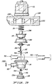
- switch gauge of the present invention is generally indicated by reference numeral 10.
- Switch gauge 10 includes a preferably transparent housing 12, a base cap 14, a calibration spring 16 and an indicator cup 18.
- Housing 12 includes a preferably generally cylindrical attachment member 20 for attachment to air intake system 22 of a vehicle's internal combustion engine, preferably via a tube 24, as shown in Figure 1.
- switch gauge 10 is shown schematically attached to a vehicle's air intake system 22, and also electrically attached to a signal means 26.
- Signal means 26 and switch gauge 10 are both powered by a power source 28, preferably the vehicle's battery.
- Signal means 26 is preferably a light mounted on the dashboard of the vehicle to provide an indicator to the driver of the vehicle, although other indicators, or combinations of indicators, such as a buzzer, a voice message, or a text message, could also be used to achieve the same result.
- the key components of switch gauge 10 also include the flexible diaphragm 30 and the lockpin 32.
- Lockpin 32 in turn is pivotally attached to and projecting upwardly from base cap 14.
- the base portion 34 of lockpin 32 engages reset button 36, which in turn is actuated by flexible reset cover 38.
- Reset spring 40 bears against base cap 14 to bias reset button 36 away from base cap 14, in turn ensuring positive contact between optional reset actuator 42 of reset cover 38 and base portion 34 of lockpin 32.
- Reset button 36 includes a bearing surface 44 which reset spring 40 bears against.
- base portion 34 of lockpin 32 include a groove along a portion of the diameter thereof (not shown) to permit compression thereof during fitment with reset button 36.
- Base portion 34 also includes a flat surface 46 which bears against a mating flat inner surface 48 on reset button 36 to insure proper positioning of the two components relative to one another. During assembly, it is also preferable to apply a small amount of adhesive to ensure the permanent retention of base portion 34 within the opening of reset button 36.
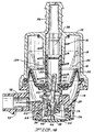
- Lockpin 32 includes several teeth 50 along one side thereof. Teeth 50 are intended for engagement with lock ring 52.
- lock ring 52 includes an opening 54 in the center thereof through which passes lockpin 32.
- the configuration of lockpin 32 combined with the effect of reset spring 40, results in a bias of lockpin 32 generally in the direction of the edge thereof having teeth 50. In other words, the edge of lockpin 32 having teeth 50 tends to bear against central opening 54 of lock ring 52.
- Calibration spring 16 bears against the upper, inside surface of housing 12 on one end, and against indicator cup 18 on the other.
- Nipple member 56 of housing 12 engages tube 24, which in turn intersects air intake 22, which carries air from air inlet F, which encloses the air filter (not shown).
- air intake 22 which carries air from air inlet F, which encloses the air filter (not shown).
- the air filter becomes dirty from extended use, the amount of air passing through it decreases, although the vehicle's internal combustion engine continues to draw air at a steady rate.
- the amount of air passing through the filter decreases, there is a corresponding decrease in the air pressure and a resulting vacuum in air intake system 22, resulting in a vacuum inside of the nipple member 56 and the corresponding inwardly projecting inner chamber 58 within housing 12.
- calibration spring 16 gradually becomes increasing compressed, as indicator cup 18 is drawn closer to nipple member 56, until lockpin 32 no longer extends into central opening 54 of lock ring 52. Then, as illustrated in Figure 5, teeth 50 no longer engage central opening 54 of lock ring 52, but rather reset spring 40 urges the distal end of toothed portion 60 of lockpin 32 into contact with the tapered lower surface 62 of lock ring 52.
- Lock ring 52 also includes a circumferentially projecting skirt 64 that prevents the distal end of toothed portion 60 of lockpin 32 from sliding past the edge of lock ring 52, which in turn, as shall be shown, ensures the simple, reliable resetting of switch gauge 10. As shown in Figure 7, lock ring skirt 64 extends sufficiently far enough from tapered lower surface 62 to permit additional compression of calibration spring 16 due to the vacuum in air intake system 22 without lockpin 32 sliding past the edge lock ring skirt 64.
- reset spring 40 biases lockpin 32 such that the lower surface of switch actuator 66 of lockpin 32 bears down on leaf 68 of normally open switch 70, pushing it against contact 74, closing the circuit illustrated in Figure 1, resulting in the activation of signal means 26, such as the illumination of a dashboard indicator light.
- Normally open switch 70 is illustrated in Figure 10.
- Figure 11 shows an alternative embodiment, normally closed switch 72, also employing a leaf 68 which bears against contact 74.
- leaf 68 is shown as part of switch assembly 76, which includes terminals 78, and connecting strips 80 forming lockpin guiding slot 82. Connecting strips 80 meet to form a distal anchoring portion 84.
- Leaf 68 is preferably attached as by being mechanically staked to the base portion 86 of switch assembly 76. Base portion 86 and anchoring portion 84 are attached to base cap 14 as by ultrasonic stakes 88, including one mounted on support post 89 (see Figure 4).
- Base cap 14 includes posts 90, 92 projecting upwardly therefrom to assure proper positioning of switch assembly 76 thereon.
- Base cap 14 also includes a connector tunnel 93 through which connection of an output line to switch terminals 78 for activation of signal means 26 is accomplished.
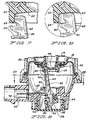
- Base cap 96 preferably includes generally horizontally disposed pockets 98 for receiving first and second retention members 100,102.
- the preferably triangularly configured receiving pockets 98, and the corresponding retention members 100, 102, also serve to assure that switch assembly 94 is accurately and consistently positioned on base cap 96.
- Base cap 96 also preferably includes first and second projecting rib portions 104, 106, with a breather port 108 positioned within first projecting rib portion 106.
- Rib portions 104, 106 help to limit the side to side motion of lockpin 32 in base cap 96. Rib portions 104, 106 also help align switch actuator portion 66 of lockpin 32 with the leaf 68 of switch assembly 94. Angled surfaces 110, 112 of rib portions 104, 106, respectively, also assist with proper assembly of lockpin 32 in base cap 96.
- switch assembly 94 preferably includes the fastening of flexible switch leaf 68 as by a rivet 114 to second retention member 102.
- Leaf 68 is preferably gold plated.
- contact 116 Projecting from an affixed to first retention member 100 is contact 116, which is preferably made of platinum. Since they provide the two terminal components of switch assembly 94, it is important that retention members 100, 102 are not in contact with each other following assembly. To this end, each is inserted through a spaced opening 118, 120, respectively, in terminal housing 122, permitting the extension of terminal portions 124, 126 of retention members 100, 102, respectively, therefrom. Also projecting outwardly from terminal housing 122 is retention tab 128 for retaining terminal housing to base cap 96, as shown in Figure 14.
- label liner 130 preferably included inside of housing 12, label liner 130 preferably having delineations 132 indicating the condition of the air filter.
- Delineations 132 preferably indicate levels of vacuum in intake system 22, with a clear marking, preferably in red, indicating when the level has reached a point that the air filter requires maintenance or replacement.
- switch gauge 10 may be installed in any orientation that is convenient to the particular application being contemplated, given the various space limitations and the like that may be encountered in various vehicle engine compartments.
- an electrical connection is formed between switch gauge 10 and a power supply 28, and then with a signal indicator 26 of some sort, such as a light or buzzer, preferably located on the dashboard of the driving compartment of the vehicle.
- the electrical connection is formed by plugging into the switch terminals 78 of base cap assembly 14, or terminal portions 124, 126 of base cap assembly 96. The respective terminals are accessible through connector tunnel 93.
- switch gauge 10 When first installed, switch gauge 10 has indicator cup 18 in the position indicated in Figures 2 and 4. As the air filter in air inlet F becomes dirtier over time through ongoing use, air flow through intake system 22 is impeded, resulting in a vacuum in the system, which is indicated by the position of indicator cup 18 as it gradually rises to the position indicated in phantom in Figure 4. As indicator cup 18 gradually rises to the position indicated in phantom in Figure 4, it is retained in position even when the engine is turned off by the latching of central opening 54 of lock ring 52 on the teeth 50 of lockpin 32. As the force of calibration spring 16 is overcome resulting in its gradual compression, the central cylinder 134 of preferably brightly colored indicator cup 18 is drawn into housing inner chamber 58.
Description
Claims (12)
- A restriction indicating device (10) for an air filter (F) used with a vehicle having an internal combustion engine, a power source and a passenger compartment, the restriction indicating device (10) being in fluid communication with the air flowing from the air filter (F) to the air intake (22) of the internal combustion engine, the restriction indicating device (10) comprising:characterized in that the restriction indicating device (10) further comprises a switch assembly (76) actuable with a switch actuator (66) integral with and projecting from said lockpin (32), said switch assembly (76) actuating an electrical circuit for activating a signal device (26) in the passenger compartment of the vehicle only when said indicator cup (18) has moved along said first axis a sufficient distance to allow the pivotal movement of said switch actuator (66) to pivot into contact with said switch assembly (76).a housing (12) having an inner chamber (58);a base cap (14) assembly attached to said housing (12);an attachment member (20) attached to the air intake system (22) of the vehicle, allowing fluid communication of the air intake system (22) with said inner chamber (58) of said housing (12);an indicator cup (18) contained within said housing (12) for indicating the vacuum level within said inner chamber (58) of said housing (12), said indicator cup (18) being slidably and linearly positionable along a first axis, between a first position indicating that the air filter is clean and a second position indicating that the air filter is dirty;a calibration spring (16) biasing said indicator cup (18) toward said first position;a diaphragm (30) attached to said indicator cup (18) and said housing (12), dividing the interior of said housing (12) from the interior of said base cap (14) assembly; anda lockpin (32) pivotally attached to said base cap (14) assembly to allow pivotal movement about a second axis that is perpendicular to said first axis, said lockpin (32) having a toothed portion (60), said toothed portion (60) thereof being positioned to retain said indicator cup (18) in a position consistent with the vacuum level of said inner chamber (58) of said housing (12),
- The air filter restriction indicating device (10) of Claim 1, further comprising:a lock ring (52) fixedly attachable to said indicator cup (18), said lock ring (52) having a central ring (62) engageable with said toothed portion (60) of said lockpin (32) and a lower lip (64) engageable with a portion of said lockpin (32), said toothed portion (60) having a plurality of teeth (50) for releasable engagement with said central ring (62) of said lock ring (52).
- The air filter restriction indicating device (10) of Claim 2, wherein said lockpin (32) is moveable between a first operating position wherein said lockpin (32) is disengaged from said lock ring (52), a second operating position wherein any one of said plurality of teeth (50) is releasably engaged with said central ring (62) of said lock ring (52), and a third operating position wherein said toothed portion (60) is disengaged from said central ring (62) and said lockpin (32) engages said lower lip (64) of said lock ring (52).
- The air filter restriction indicating device (10) of Claim 3 wherein said switch assembly (76) is actuated by said switch actuator (66) only when said lockpin (32) is in said third position.
- The air filter restriction indicating device (10) of any preceding claim, further comprising:a reset assembly, said reset assembly comprising:a reset button (36) pivotally connected to said base cap (14) assembly and engageable with a lockpin base portion (34) extending from said lockpin (32); anda reset spring (40) biasing said reset button (36) toward a neutral position, whereby depressing said reset button (36) overcomes the bias of said reset spring (40), and disengages said central ring (62) of said lock ring (52) from said toothed portion (60) of said lockpin (32), permitting movement of said indicator cup (18) from said second position to said first position.
- The air filter restriction indicating device (10) of any preceding claim, wherein said switch assembly (76) comprises:a switch actuator (66) projecting from said lockpin (32);a base portion (34) mounted to said base cap (14) assembly;a flexible leaf portion (68) fixedly attached to and biased away from said base portion (34), said leaf portion (68) extending outwardly for contact with said switch actuator (66) of said lockpin (32);at least one switch terminal (78) attached to and projecting from said base portion (34) for electrical communication with the signalling device (26) in the passenger compartment of the vehicle; anda switch contact (74) fixedly attached to said base portion (34), for contact with said leaf portion (68), whereby said switch assembly (76) is normally open, and the loading of the air filter results in said indicator cup (18) moving toward a said third position, resulting in said switch actuator (66) bearing against said leaf portion (68) until it contacts said switch contact (74), closing a circuit energized by the vehicle power source, and thereby actuating said signal device (26) in the passenger compartment of the vehicle.
- The air filter restriction indicating device (10) of Claim 6, further comprising:a plurality of posts (90, 92) projecting from said base portion (34), whereby said posts (90, 92) abut against and engage said base portion (34) to maintain said base portion (34) in fixed position relative to said lockpin (32) switch actuator (66).
- The air filter restriction indicating device (10) of any one of Claims 1 to 5, wherein said switch assembly (76) comprises:a switch actuator (66) projecting from said lockpin (32);a base portion (34) mounted to said base cap (14) assembly;a flexible leaf portion (68) fixedly attached to and biased away from said base portion (34), said leaf portion (68) extending outwardly for contact with said switch actuator (66) of said lockpin (32);at least one switch terminal (78) attached to and projecting from said base portion (34) for electrical communication with the signalling device (26) in the passenger compartment of the vehicle; anda switch contact (74) fixedly attached to said base portion (34), for contact with said leaf portion (68), whereby said switch assembly (76) is normally closed, and the loading of the air filter results in said indicator cup (18) moving toward a third position, resulting in said switch actuator (66) bearing against said leaf portion (68) until it breaks contact with said switch contact (74), opening a circuit energised by the vehicle power source, and thereby actuating said signal device (26) in the passenger compartment of the vehicle.
- The air filter restriction indicating device (10) of any one of Claims 1 to 5, wherein said switch assembly (76) comprises:a switch actuator (66) projecting from said lockpin (32);at least one retention member (100, 102) for engagement with an at least one corresponding retention pocket (98) on said base cap (14) assembly, whereby said at least one retention pocket (98) assists in the proper positioning of said switch assembly (76) with respect to said base cap (14) assembly;a flexible leaf portion (68) fixedly attached to and biased away from said at least one retention member (100, 102), said leafportion (68) extending outwardly for contact with said switch actuator (66) of said lockpin (32);at least one switch terminal (124, 126) attached to and projecting from said at least one retention member (100, 102), for electrical communication with the signalling device (26) in the passenger compartment of the vehicle; anda switch contact (116) fixedly attached to said at least one retention member (100,102), for contact with said leaf portion (68), whereby said switch assembly (76) is normally open, and the loading of the air filter results in said indicator cup (18) moving toward said second position, resulting in said switch actuator (66) bearing against said leaf portion (68) until it contacts said switch contact (116), closing a circuit energized by the vehicle power source, and thereby actuating said signal device (26) in the passenger compartment of the vehicle.
- The air filter restriction indicating device (10) of any one of claims 6 to 9, further comprising:a terminal housing (122) including a first aperture (118) for securely receiving one of said at least one switch terminal (78, 124); anda retention tab (128) projecting from said terminal housing (122) for secure engagement with said base cap (14) assembly.
- The air filter restriction indicating device (10) of Claim 10, further comprising:a second switch terminal (78, 126) projecting from a second retention member (102), said second retention member (102) engageable with a second retention pocket (98) on said base cap (14) assembly, anda second aperture (120) on said terminal housing (122) for securely receiving said second switch terminal (78, 126).
- The air filter restriction indicating device (10) of any preceding claim, further comprising:first and second rib portions (104, 106) projecting outwardly from said base cap (14) assembly, whereby said rib portions (104, 106) assure proper positioning of said lockpin (32) with respect to said switch assembly (76).
Applications Claiming Priority (3)
| Application Number | Priority Date | Filing Date | Title |
|---|---|---|---|
| US310621 | 1999-05-12 | ||
| US09/310,621 US6268791B1 (en) | 1999-05-12 | 1999-05-12 | Switch gauge |
| PCT/US2000/012650 WO2000070215A1 (en) | 1999-05-12 | 2000-05-10 | Switch gauge |
Publications (2)
| Publication Number | Publication Date |
|---|---|
| EP1179133A1 EP1179133A1 (en) | 2002-02-13 |
| EP1179133B1 true EP1179133B1 (en) | 2005-07-27 |
Family
ID=23203369
Family Applications (1)
| Application Number | Title | Priority Date | Filing Date |
|---|---|---|---|
| EP00932212A Expired - Lifetime EP1179133B1 (en) | 1999-05-12 | 2000-05-10 | Switch gauge |
Country Status (5)
| Country | Link |
|---|---|
| US (1) | US6268791B1 (en) |
| EP (1) | EP1179133B1 (en) |
| JP (1) | JP2002544436A (en) |
| DE (1) | DE60021559T2 (en) |
| WO (1) | WO2000070215A1 (en) |
Families Citing this family (6)
| Publication number | Priority date | Publication date | Assignee | Title |
|---|---|---|---|---|
| US6327902B1 (en) * | 1999-06-25 | 2001-12-11 | Engineered Products Company | Air filter restriction indicator gauge |
| WO2001012974A1 (en) * | 1999-08-16 | 2001-02-22 | Donaldson Company, Inc. | Restriction indicator |
| US7032573B2 (en) * | 2004-04-23 | 2006-04-25 | Ford Global Technologies, Llc | Method and apparatus for indicating air filter maintenance is required |
| WO2006081564A1 (en) * | 2005-01-28 | 2006-08-03 | Engineered Products Company | Non-locking switch for filter monitoring |
| FR2973072B1 (en) * | 2011-03-22 | 2013-03-22 | IFP Energies Nouvelles | METHOD FOR CONTROLLING A SUPERIOR INTERNAL COMBUSTIBLE ENGINE WITH A CONTROL IGNITION FOR A MOTOR VEHICLE |
| EP4074404A1 (en) | 2017-10-24 | 2022-10-19 | Donaldson Company, Inc. | Air cleaner assembly with restriction indicator |
Family Cites Families (9)
| Publication number | Priority date | Publication date | Assignee | Title |
|---|---|---|---|---|
| FR2246856B1 (en) * | 1973-10-03 | 1978-03-17 | Sofiltra Ste Indle Filtration | |
| US3939457A (en) * | 1974-11-07 | 1976-02-17 | Richard Donald Nelson | Air filter restriction indicating device |
| US4445456A (en) * | 1978-06-19 | 1984-05-01 | Engineered Products Company | Air filter restriction indicating device |
| US4369728A (en) | 1981-02-09 | 1983-01-25 | Engineered Products Company | Air filter restriction indicating device |
| JP2621264B2 (en) * | 1987-12-18 | 1997-06-18 | 株式会社デンソー | ▲ Ro ▼ Detector for clogging of excess element |
| GB2297161B (en) * | 1995-01-23 | 1998-09-23 | Pall Corp | Differential pressure indicators |
| US5850183A (en) * | 1995-02-24 | 1998-12-15 | Engineered Products Co. | Air filter restriction indicating device |
| DE19506453A1 (en) * | 1995-02-24 | 1996-08-29 | Mann & Hummel Filter | Display device for displaying the negative pressure |
| US5774056A (en) * | 1996-05-30 | 1998-06-30 | Engineered Products Co. | Gauge for monitoring air filters |
-
1999
- 1999-05-12 US US09/310,621 patent/US6268791B1/en not_active Expired - Lifetime
-
2000
- 2000-05-10 DE DE60021559T patent/DE60021559T2/en not_active Expired - Lifetime
- 2000-05-10 WO PCT/US2000/012650 patent/WO2000070215A1/en active IP Right Grant
- 2000-05-10 JP JP2000618608A patent/JP2002544436A/en not_active Abandoned
- 2000-05-10 EP EP00932212A patent/EP1179133B1/en not_active Expired - Lifetime
Also Published As
| Publication number | Publication date |
|---|---|
| DE60021559D1 (en) | 2005-09-01 |
| WO2000070215A1 (en) | 2000-11-23 |
| JP2002544436A (en) | 2002-12-24 |
| DE60021559T2 (en) | 2006-01-12 |
| US6268791B1 (en) | 2001-07-31 |
| EP1179133A1 (en) | 2002-02-13 |
Similar Documents
| Publication | Publication Date | Title |
|---|---|---|
| US4445456A (en) | Air filter restriction indicating device | |
| US3939457A (en) | Air filter restriction indicating device | |
| EP1179133B1 (en) | Switch gauge | |
| ES2402679T3 (en) | Vehicle detection device | |
| US20060139177A1 (en) | Low oil level indicator | |
| US5842763A (en) | Illuminated cover for containers, tanks and the like | |
| ZA200208664B (en) | Apparatus for automatically draining water accumulated in a fuel filter of a vehicle, particularly for diesel engines. | |
| JP2018135879A (en) | Fuel filter | |
| US4189724A (en) | Electric restriction indicator with a contactless switch device for indicating a restriction in filter elements | |
| US20030089648A1 (en) | Apparatus for automatically draining water accumulated in a fuel filter of a vehicle, particularly for diesel engines | |
| EP1192350B1 (en) | Fuel filter gauge | |
| US6307466B1 (en) | Two stage gauge with electrical signal output | |
| US5101327A (en) | Dipstick locator | |
| US20060192570A1 (en) | Apparatus for monitoring consumable parts | |
| US4189707A (en) | Engine air intake warning system | |
| CN210397537U (en) | Wear indicator for drum brake | |
| CN112721630B (en) | Vehicle-mounted drunk driving prevention device and system thereof | |
| CN101143548B (en) | Tyre pressure safety alarming device for tyre | |
| KR200335651Y1 (en) | Implement to indicate electrolyte of car battery | |
| EP0198947A1 (en) | Liquid level checking system for vehicles | |
| JPH08108019A (en) | Filter with differential pressure indicator | |
| JPS6118543A (en) | Alarm for insufficient window washer liquid for car | |
| KR970034025A (en) | Puncture detection device of automobile tire | |
| CN107290307A (en) | For the fuel testing device of vehicle fuel cleaner and the vehicle with it | |
| KR960013711A (en) | Tire pressure measurement device with alarm |
Legal Events
| Date | Code | Title | Description |
|---|---|---|---|
| PUAI | Public reference made under article 153(3) epc to a published international application that has entered the european phase |
Free format text: ORIGINAL CODE: 0009012 |
|
| 17P | Request for examination filed |
Effective date: 20011017 |
|
| AK | Designated contracting states |
Kind code of ref document: A1 Designated state(s): AT BE CH CY DE DK ES FI FR GB GR IE IT LI LU MC NL PT SE |
|
| 17Q | First examination report despatched |
Effective date: 20040406 |
|
| RBV | Designated contracting states (corrected) |
Designated state(s): DE FR GB IT |
|
| GRAP | Despatch of communication of intention to grant a patent |
Free format text: ORIGINAL CODE: EPIDOSNIGR1 |
|
| GRAS | Grant fee paid |
Free format text: ORIGINAL CODE: EPIDOSNIGR3 |
|
| GRAA | (expected) grant |
Free format text: ORIGINAL CODE: 0009210 |
|
| AK | Designated contracting states |
Kind code of ref document: B1 Designated state(s): DE FR GB IT |
|
| REG | Reference to a national code |
Ref country code: GB Ref legal event code: FG4D |
|
| REF | Corresponds to: |
Ref document number: 60021559 Country of ref document: DE Date of ref document: 20050901 Kind code of ref document: P |
|
| ET | Fr: translation filed | ||
| PLBE | No opposition filed within time limit |
Free format text: ORIGINAL CODE: 0009261 |
|
| STAA | Information on the status of an ep patent application or granted ep patent |
Free format text: STATUS: NO OPPOSITION FILED WITHIN TIME LIMIT |
|
| 26N | No opposition filed |
Effective date: 20060428 |
|
| PGFP | Annual fee paid to national office [announced via postgrant information from national office to epo] |
Ref country code: IT Payment date: 20080527 Year of fee payment: 9 |
|
| REG | Reference to a national code |
Ref country code: FR Ref legal event code: ST Effective date: 20100129 |
|
| PG25 | Lapsed in a contracting state [announced via postgrant information from national office to epo] |
Ref country code: FR Free format text: LAPSE BECAUSE OF NON-PAYMENT OF DUE FEES Effective date: 20090602 |
|
| PGFP | Annual fee paid to national office [announced via postgrant information from national office to epo] |
Ref country code: FR Payment date: 20080519 Year of fee payment: 9 |
|
| PG25 | Lapsed in a contracting state [announced via postgrant information from national office to epo] |
Ref country code: IT Free format text: LAPSE BECAUSE OF NON-PAYMENT OF DUE FEES Effective date: 20090510 |
|
| REG | Reference to a national code |
Ref country code: GB Ref legal event code: 732E Free format text: REGISTERED BETWEEN 20170504 AND 20170510 |
|
| REG | Reference to a national code |
Ref country code: DE Ref legal event code: R082 Ref document number: 60021559 Country of ref document: DE Representative=s name: BOEHMERT & BOEHMERT ANWALTSPARTNERSCHAFT MBB -, DE Ref country code: DE Ref legal event code: R081 Ref document number: 60021559 Country of ref document: DE Owner name: DONALDSON COMPANY, INC. (N.D.GES.D. STAATES DE, US Free format text: FORMER OWNER: ENGINEERED PRODUCTS CO., WATERLOO, IA., US |
|
| PGFP | Annual fee paid to national office [announced via postgrant information from national office to epo] |
Ref country code: DE Payment date: 20190530 Year of fee payment: 20 |
|
| PGFP | Annual fee paid to national office [announced via postgrant information from national office to epo] |
Ref country code: GB Payment date: 20190528 Year of fee payment: 20 |
|
| REG | Reference to a national code |
Ref country code: DE Ref legal event code: R071 Ref document number: 60021559 Country of ref document: DE |
|
| REG | Reference to a national code |
Ref country code: GB Ref legal event code: PE20 Expiry date: 20200509 |
|
| PG25 | Lapsed in a contracting state [announced via postgrant information from national office to epo] |
Ref country code: GB Free format text: LAPSE BECAUSE OF EXPIRATION OF PROTECTION Effective date: 20200509 |