EP1178710A1 - Electric discharge lamp starter and lighting system - Google Patents
Electric discharge lamp starter and lighting system Download PDFInfo
- Publication number
- EP1178710A1 EP1178710A1 EP00902926A EP00902926A EP1178710A1 EP 1178710 A1 EP1178710 A1 EP 1178710A1 EP 00902926 A EP00902926 A EP 00902926A EP 00902926 A EP00902926 A EP 00902926A EP 1178710 A1 EP1178710 A1 EP 1178710A1
- Authority
- EP
- European Patent Office
- Prior art keywords
- discharge lamp
- voltage
- current
- lighting device
- commercial
- Prior art date
- Legal status (The legal status is an assumption and is not a legal conclusion. Google has not performed a legal analysis and makes no representation as to the accuracy of the status listed.)
- Granted
Links
Images




Classifications
-
- H—ELECTRICITY
- H05—ELECTRIC TECHNIQUES NOT OTHERWISE PROVIDED FOR
- H05B—ELECTRIC HEATING; ELECTRIC LIGHT SOURCES NOT OTHERWISE PROVIDED FOR; CIRCUIT ARRANGEMENTS FOR ELECTRIC LIGHT SOURCES, IN GENERAL
- H05B41/00—Circuit arrangements or apparatus for igniting or operating discharge lamps
- H05B41/14—Circuit arrangements
- H05B41/26—Circuit arrangements in which the lamp is fed by power derived from DC by means of a converter, e.g. by high-voltage DC
- H05B41/28—Circuit arrangements in which the lamp is fed by power derived from DC by means of a converter, e.g. by high-voltage DC using static converters
- H05B41/288—Circuit arrangements in which the lamp is fed by power derived from DC by means of a converter, e.g. by high-voltage DC using static converters with semiconductor devices and specially adapted for lamps without preheating electrodes, e.g. for high-intensity discharge lamps, high-pressure mercury or sodium lamps or low-pressure sodium lamps
- H05B41/2885—Static converters especially adapted therefor; Control thereof
- H05B41/2887—Static converters especially adapted therefor; Control thereof characterised by a controllable bridge in the final stage
- H05B41/2888—Static converters especially adapted therefor; Control thereof characterised by a controllable bridge in the final stage the bridge being commutated at low frequency, e.g. 1kHz
-
- H—ELECTRICITY
- H05—ELECTRIC TECHNIQUES NOT OTHERWISE PROVIDED FOR
- H05B—ELECTRIC HEATING; ELECTRIC LIGHT SOURCES NOT OTHERWISE PROVIDED FOR; CIRCUIT ARRANGEMENTS FOR ELECTRIC LIGHT SOURCES, IN GENERAL
- H05B41/00—Circuit arrangements or apparatus for igniting or operating discharge lamps
- H05B41/14—Circuit arrangements
- H05B41/26—Circuit arrangements in which the lamp is fed by power derived from DC by means of a converter, e.g. by high-voltage DC
- H05B41/28—Circuit arrangements in which the lamp is fed by power derived from DC by means of a converter, e.g. by high-voltage DC using static converters
- H05B41/288—Circuit arrangements in which the lamp is fed by power derived from DC by means of a converter, e.g. by high-voltage DC using static converters with semiconductor devices and specially adapted for lamps without preheating electrodes, e.g. for high-intensity discharge lamps, high-pressure mercury or sodium lamps or low-pressure sodium lamps
- H05B41/2885—Static converters especially adapted therefor; Control thereof
- H05B41/2886—Static converters especially adapted therefor; Control thereof comprising a controllable preconditioner, e.g. a booster
-
- Y—GENERAL TAGGING OF NEW TECHNOLOGICAL DEVELOPMENTS; GENERAL TAGGING OF CROSS-SECTIONAL TECHNOLOGIES SPANNING OVER SEVERAL SECTIONS OF THE IPC; TECHNICAL SUBJECTS COVERED BY FORMER USPC CROSS-REFERENCE ART COLLECTIONS [XRACs] AND DIGESTS
- Y02—TECHNOLOGIES OR APPLICATIONS FOR MITIGATION OR ADAPTATION AGAINST CLIMATE CHANGE
- Y02B—CLIMATE CHANGE MITIGATION TECHNOLOGIES RELATED TO BUILDINGS, e.g. HOUSING, HOUSE APPLIANCES OR RELATED END-USER APPLICATIONS
- Y02B20/00—Energy efficient lighting technologies, e.g. halogen lamps or gas discharge lamps
Definitions
- This invention relates to a discharge lamp lighting device with a power source of an commercial AC and an illumination device equipped with the discharge lamp lighting device, and more particularly to those capable of lighting the discharge lamp with high power factor.
- FIG. 9 is a circuit diagram of a conventional discharge lamp device which is disclosed in e.g. JP-A-9-45490.
- reference numeral 101 denotes a commercial power source; 102 a rectifying circuit; 103 a voltage boosting inverter; 104 a voltage dropping inverter; 105 a square wave circuit; 106 a starting circuit; 107 a discharge lamp; 108 a voltage-boosting inverter control circuit; 109 a voltage-dropping inverter control circuit; 110 a square wave control circuit; and 111 a control power source circuit.
- control power source circuit 111 creates control power which is fed to the voltage-boosting inverter circuit 108, voltage dropping circuit 109 and square-wave control circuit 110. As a result, these circuits start to operate.
- the AC power from the commercial AC power source 101 is rectified by the rectifying circuit 102, and the rectified power is applied to the voltage boosting inverter 103.
- the voltage-boosting inverter 103 converts the applied DC voltage into a DC voltage of 400 V.
- the voltage boosting inverter control circuit 108 corrects wave distortion of an input current supplied to the voltage-boosting inverter 103 to control the voltage-boosting inverter 103 so that the input power factor is approximately 100 %.
- the voltage-dropping inverter 104 inverts the DC voltage supplied from the voltage-boosting inverter 103 into a DC voltage corresponding to a load change in the discharge lamp 107. Then, the voltage-dropping-inverter control circuit 109 controls the output voltage from the voltage dropping inverter 104 so that the current flowing through the discharge lamp 107 is a prescribed current, e.g. a constant current of 2 A.
- the square wave circuit 105 converts the DC voltage applied from the voltage dropping inverter 104 into an AC square wave. Then, the square wave control circuit 110 controls the square wave circuit 105 so that the current flowing through the discharge lamp 107 is an AC square wave at a prescribed frequency of e.g. 100 Hz.
- the starting circuit 106 generates a high voltage pulse by the AC square wave from the square wave circuit 105 to start the lighting of the discharge lamp 107.
- the discharge lamp device which has a low power factor exerts an adverse effect on a commercial AC power system facility so that the discharge lamp device with a high power factor has been demanded.
- the AC voltage In order to give the high power factor to the device, as in the conventional discharge lamp device, using the voltage boosting inverter 103, the AC voltage must be converted into a DC voltage.
- the discharge lamp device is equipped with the voltage-boosting inverter 103
- the voltage-boosting inverter 103 itself is bulky, heavy and expensive
- the discharge lamp device also becomes bulky, heavy and expensive.
- This invention has been accomplished in order to solve the problem described above, and intends to provide a discharge lamp lighting device and illumination device which can be miniaturized with a high power factor and also is inexpensive.
- the discharge lamp lighting device is characterized by comprising:
- the discharge lamp lighting device is also characterized in that when the polarity of the current passed through the discharge lamp by the polarity 'changing circuit is changed at a frequency equal to or higher than that of the commercial AC power source, it is changed at least in the vicinity of the phases of 0° and 180° thereof.
- the discharge lamp lighting device is also characterized in that when the polarity of the current passed through the discharge lamp by the polarity changing circuit is changed at a frequency equal to or higher than that of the commercial AC power source, it is changed at least in the vicinity of the phases of 90° and 270° thereof.
- the discharge lamp lighting device is also characterized in that the detecting section has a function of detecting the phase of the commercial AC power source, and the control section controls the voltage boosting/dropping circuit and the polarity changing circuit changes the polarity of the flowing current so that the current flowing through the discharge lamp is substantially in phase with that of the commercial AC power source voltage and has a substantially sine waveform.
- the discharge lamp lighting device is also characterized in that the current flowing through the discharge lamp is constant in the vicinity of the phases of 90° and 270°.
- the discharge lamp lighting device is also characterized in that the current flowing through the discharge lamp is the square of the sine wave in synchronism with the commercial AC power source voltage.
- the discharge lamp lighting device is also characterized by further comprising a voltage detecting section for detecting the voltage across the discharge lamp, and in that in response to the detected value from the voltage detecting section, the control section controls the voltage boosting/dropping circuit so that electric power supplied to the discharge lamp is constant.
- the illumination device according to this invention is characterized by having a discharge lamp lighting device defined in any one of the discharge lamp lighting device described above.
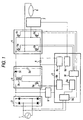
- FIG. 1 is a block diagram showing an arrangement of a discharge lamp lighting device according to the first embodiment of this invention
- Fig. 2 is a waveform chart showing the operation of the discharge lamp lighting device according to the first embodiment of this invention.
- reference numeral 1 denotes a commercial AC power source
- 2 a rectifying circuit of a diode bridge which serves to full-wave rectify a commercial AC voltage
- 3 a voltage boosting/dropping converter for boosting or dropping the full-wave rectified voltage.
- the voltage boosting/dropping converter 3 includes a switching element 3a, a transformer 3b, a diode 3c and a capacitor 3d.
- Reference numeral 4 denotes a current detecting resistor for detecting a current flowing through a discharge lamp 6
- reference numeral 5 denotes a polarity-changing circuit for changing the polarity of the current flowing through a discharge lamp 6.
- the polarity-changing circuit 5 includes a switching element 5a, a switching element 5b, a switching element 5c and a switching element 5d.
- Reference numeral 6 denotes a discharge lamp; 7 a starting pulse generating circuit for generating a high voltage pulse to start the discharge lamp; and 8 a control power source creating circuit for creating a control power source.
- Reference numeral 9 denotes a control circuit which includes a detecting unit 9a for detecting a zero-crossing of a commercial AC, a control unit 9b for controlling the voltage boosting/dropping converter 3, a current detecting unit 9c for detecting the current flowing through the discharge lamp 6 based on the current detecting resistor 4, a starting pulse control unit 9d for controlling the starting pulse generating circuit 7, a target current computing unit 9e and a control unit 9f for controlling the polarity changing circuit 5.
- Fig. 2 shows a current/voltage waveform of the commercial AC power source 1;
- (b) shows an ON/OFF state of the switching element 5a and a switching element 5d of the polarity changing circuit 5;
- (c) shows an ON/OFF state of the switching element 5b and a switching element 5c of the polarity changing circuit 5;
- (d) shows a target current computed by the target current computing unit 9e; and
- (e) shows a current flowing through the discharge lamp 6.
- the control power source creating circuit 8 creates the control power source to be supplied to the control circuit 9. Then, the control circuit 9 starts to operate.
- the starting pulse control unit 9d controls the starting pulse generating circuit 7, which in turn supplies a high voltage pulse to the discharge lamp 6. Then, the discharge lamp is lit.
- the discharge lamp When the discharge lamp is lit, a current starts to flow to the current detecting resistor 4. This current is detected by the current detecting unit 9c.
- the target current computing unit 9e computes the target current.
- the control unit 9b compares the current detected by the current detecting unit 9c and the target current computed by the target current computing unit 9e and controls the voltage boosting/dropping converter 3 so that the detected current and the target current become equal to each other, thereby making feedback control.
- the switching element 3a repeats ON/OFF at a high frequency of several tens of kHz.
- the switching element 3a When the switching element 3a is "ON”, a current flows to the primary side of the transformer 3b where energy is stored.
- the switching element 3a When the switching element 3a is "OFF”, the stored energy is discharged to the secondary side of the transformer 3b as electric power. Since the discharged electric power is at a high frequency of several tens kHz, the high frequency component is removed by the diode 3c and the capacitor 3d, and the resultant power is supplied to the discharge lamp 6.
- the control unit 9b increases the time of "ON" of the switching element 3a thereby to increase the electric power to be discharged to the secondary side, thereby increasing the current flowing through the discharge lamp 6.
- the control unit 9b decreases the time of "ON" of the switching element 3a to decrease the electric power to be discharged to the secondary side, thereby decreasing the current flowing through the discharge lamp 6.
- the control unit 9f controls the polarity changing circuit 5 so that a set of the switching elements 5a and 5d and another set of the switching elements 5c and 5b are alternately turned ON.
- the DC current from the voltage boosting/dropping converter 3 is converted into an AC current, which flows through the discharge lamp 6.
- the detecting unit 9a produces a zero-crossing detected signal when the voltage in the commercial AC becomes zero volt in its periodic change.
- the target current computing unit 9e computes the target current on the basis of the commercial AC voltage waveform as shown in Fig. 2(a) so that it is small in the vicinity of 0° and 180° and large in the vicinity of 90° and 270° as shown in Fig. 2(d).
- control unit 9f changes the set of the switching elements 5a and 5d between their "ON” and “OFF” as shown in Fig. 2 (b) and changes the switching elements 5c and 5b between their "ON” and “OFF” as shown in Fig. 2 (c).
- the current flowing through the discharge lamp 6 becomes a sinusoidal wave current whose polarity is changed at 0° and 180° and synchronous with the commercial AC power source 1 shown in Fig. 2(a).
- the current flowing into the discharge lamp lighting device from the commercial AC power source 1 is proportional to the current flowing through the discharge lamp 6. Therefore, the input current for the discharge lamp lighting device is also the sinusoidal wave current synchronous with the commercial AC power source 1, thereby increasing the input power factor.
- unneccessity of a power factor improving circuit such as a voltage boosting inverter can provides a compact and inexpensive discharge lamp lighting device.
- FIG. 1 is a block diagram showing an arrangement of a discharge lamp lighting device according to the second embodiment of this invention, which is the same as that of the first embodiment.
- Fig. 3 is a waveform chart showing the operation of the discharge lamp lighting device according to the second embodiment of this invention.
- Fig. 3 shows a current/voltage waveform of the commercial AC power source 1;
- (b) shows a light flux discharged from the discharge lamp 6 before improvement;
- (c) shows an ON/OFF state of the switching element 5a and a switching element 5d of the polarity changing circuit 5;
- (d) shows an ON/OFF state of the switching element 5b and a switching element 5c of the polarity changing circuit 5;
- (e) shows a target current computed by the target current computing unit 9e;
- (f) shows a current flowing through the discharge lamp 6;
- (g) shows a light flux discharged from the discharge lamp 6 after improvement; and
- (h) shows a current flowing through the discharge lamp 6.
- the polarity of the current which is to be passed through the discharge lamp 6 is changed at 0° and 180° of the commercial AC power source as shown in Fig. 2 (e) .
- the size of the light flux discharged from the discharge lamp 6 provides a level difference between the polarities as shown in Fig. 3(b).
- Such a phenomenon is attributable to the fact that there is a difference in the light emission efficiency between the polarities even when the current with the same value between the positive and negative polarities is passed through the discharge lamp.
- Connecting the peaks of the light fluxes in Fig. 3(b) gives a pulsating wave as shown in Fig. 3(i). Human's eyes are susceptible to such a pulsating wave at a low frequency as flicker.
- the control unit 9f controls the polarity changing circuit 5 so that for the commercial AC voltage waveform of Fig. 3(a), the ON/OFF states of a set of the switching elements 5a and 5b and of another set of the switching elements 5b and 5c are changed at 90° and 270° as shown in Fig. 3(c) and Fig. 3(d), respectively.
- the polarity of the target current shown in Fig. 3(e) computed by the target current computing unit 9e and produced from the voltage boosting/dropping converter 3 is changed by the polarity changing circuit 5 as shown in Fig. 3 (f) .
- the current which is small in the vicinity of 0° and 180° and large in the vicinity of 90° and 270° flows through the discharge lamp 6.
- the current flowing through the discharge lamp 6 is substantially in phase with the commercial AC power source voltage and its absolute value is controlled by the sinusoidal wave current.
- the size of the light flux discharged from the discharged lamp 6 is such as shown in Fig. 3(g) and provides a uniform peak value.
- the human's eyes are difficult to susceptible to such a light flux as flicker as compared with the first embodiment.
- FIG. 4 is a block diagram showing an arrangement of a oischarge lamp lighting device according to the third embodiment of this invention.
- the current detecting resistor 4 is located between the rectifying circuit 2 and the voltage boosting/dropping converter 3.
- the remaining structure is the same as that of the discharge lamp lighting device according to the first embodiment or the second embodiment.
- the resistor 4 was used to detect the discharge lamp current in the discharge lamp lighting device according to the first embodiment or the second embodiment.
- the resistor 4 is used to detect the input current to the discharge lamp lighting device.
- the target current is computed so that the detected input current is small in the vicinity of 0° and 180°, and large in the vicinity of 90° and 270°.
- the control unit 9b controls the voltage boosting/dropping converter 3 so that the target current is equal to the detected current from the current detecting unit 9c, thereby making feedback control.
- the input current for the discharge lamp lighting device is also the sinusoidal wave current synchronous with the commercial AC power source 1, thereby increasing the input power factor.
- a power factor improving circuit such as a voltage boosting inverter can provides a compact and inexpensive discharge lamp lighting device.
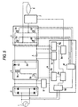
- FIG. 5 is a block diagram showing an arrangement of a discharge lamp lighting device according to the fourth embodiment of this invention.
- reference numeral 9g denotes a discharge lamp voltage detecting unit provided in the control circuit 9.
- the remaining structure is the same as that of the discharge lamp lighting device according to the first embodiment or the second embodiment.
- the target current computing unit 9e decreases the amplitude of the target current, for example, when the discharge lamp voltage is 100 V, the amplitude of the target current is reduced to 1.5 A.
- the amplitude of the target current is increased, for example, when the discharge lamp voltage is 75 V, the amplitude of the target current is increased to 2.0 A.
- the control unit 9b controls the voltage boosting/dropping converter 3 so that the target current is equal to the detected current from the current detecting unit 9c, thereby making feedback control.
- the power supplied to the discharge lamp remains constant regardless with a difference in the discharge lamp voltage due to the secular change of the discharge lamp and difference in bodies, and hence the discharge lamp provide constant brightness.
- FIG. 6 is a block diagram showing an arrangement of a discharge lamp lighting device according to the fifth embodiment of this invention.
- reference numeral 1 denotes a commercial AC power source
- 2 a rectifying circuit of a diode bridge which serves to full-wave rectify a commercial AC voltage
- 3 a voltage boosting/dropping converter for boosting or dropping the full-wave rectified voltage.
- the voltage boosting/dropping converter 3 includes a switching element 3a, a transformer 3b, a diode 3c, a diode 3f, a capacitor 3d and a capacitor 3e.
- Reference numeral 4 denotes a current detecting resistor for detecting a current flowing through a discharge lamp 6, and reference numeral 5 denotes a polarity-changing circuit for changing the polarity of the current flowing through a discharge lamp 6.
- the polarity-changing circuit 5 includes a switching element 5a and a switching element 5b.
- Reference numeral 6 denotes a discharge lamp; 7 a starting pulse generating circuit for generating a high voltage pulse to start the discharge lamp 6; and 8 a control power source creating circuit for creating a control power source.
- Reference numeral 9 denotes a control circuit which includes a detecting unit 9a for detecting a zero-crossing of a commercial AC, a control unit 9b for controlling the voltage boosting/dropping converter 3, a current detecting unit 9c for detecting the current flowing through the discharge lamp 6 based on the current detecting resistor 4, a starting pulse control unit 9d for controlling the starting pulse generating circuit 7, a target current computing unit 9e and a control unit 9f for controlling the polarity changing circuit 5.
- the control power source creating circuit 8 creates the control power source to be supplied to the control circuit 9. Then, the control circuit 9 starts to operate.
- the starting pulse control unit 9d controls the starting pulse generating circuit 7, which in turn applies a high voltage pulse to the discharge lamp 6. Then, the discharge lamp 6 is lit.
- the discharge lamp 6 When the discharge lamp 6 is lit, a current starts to flow through the current detecting resistor 4. This current is detected by the current detecting unit 9c.
- the target current computing unit 9e computes the target current.
- the control unit 9b compares the current detected by the current detecting unit 9c and the target current computed by the target current computing unit 9e and controls the voltage boosting/dropping converter 3 so that the detected current and the target current become equal to each other, thereby making feedback control.
- the switching element 3a repeats ON/OFF at a high frequency of several tens of kHz.
- the switching element 3a When the switching element 3a is "ON”, a current flows to the primary side of the transformer 3b where energy is stored.
- the switching element 3a when the switching element 3a is "OFF”, the stored energy is discharged to the secondary side of the transformer 3b as electric power.
- the control unit 9b increases the time of "ON" of the switching element 3a thereby to increase the electric power to be discharged to the secondary side, thereby increasing the current flowing through the discharge lamp 6.
- the control unit 9b decreases the time of "ON" of the switching element 3a to decrease the electric power to be discharged to the secondary side, thereby decreasing the current flowing through the discharge lamp 6.
- the control unit 9f controls the polarity changing circuit 5 so that the switching elements 5a and 5b are alternately turned ON. Thus, an AC current flows through the discharge lamp 6.
- the detecting unit 9a detects zero-crossings and the period between the zero-crossings of the commercial AC power source 1.
- the target current computing unit 9e computes the target current on the basis of the commercial AC voltage waveform as shown in Fig. 2(a) so that it is small in the vicinity of 0° and 180° and large in the vicinity of 90° and 270° as shown in Fig. 2(d).
- control unit 9f changes the switching element between the switching elements 5a and 5b at 0° and 180° of the commercial AC power source so that the current flowing through the discharge lamp 6 is inverted at 0° and 180°.
- the current flowing through the discharge lamp 6 becomes a sinusoidal wave current which is synchronous with the commercial AC power source 1.
- the current flowing into the discharge lamp lighting device from the commercial AC power source 1 is proportional to the current flowing through the discharge lamp 6. Therefore, the input current for the discharge lamp lighting device is also the sinusoidal wave current synchronous with the commercial AC power source 1, thereby increasing the input power factor.
- unneccessity of a power factor improving circuit such as a voltage boosting inverter can provides a compact and inexpensive discharge lamp lighting device.
- control unit 9f changes the switching element between the switching elements 5a and 5b at 90° and 270° of the commercial AC power source power source so that the current flowing through the discharge lamp 6 is inverted at 90° and 270°.
- the size of the light flux discharged from the discharged lamp 6 provides a uniform peak value.
- the human's eyes are difficult to susceptible to such a light flux as flicker.
- FIG. 7 is a waveform chart showing the operation of the discharge lamp lighting device according to the sixth embodiment of this invention.
- FIG. 7 shows a current/voltage of the commercial AC voltage of the commercial AC power source 1; (b) shows a target current computed by the target current computing unit 9e according to the first to fifth embodiments; and (c) shows the target current computed by the target computing unit 9e according to this embodiment, which is flat in the vicinity of 90° and 270°.
- the target current computing unit 9e computes the target current shown in Fig. 7(c).
- the control unit 9b compares the current detected by the current detecting unit 9c and the target current computed by the target current computing unit 9e and controls the voltage boosting/dropping converter 3 so that the detected current and the target current become equal to each other, thereby making feedback control.
- FIG. 8 is a waveform chart showing the operation of the discharge lamp lighting device according to the sixth embodiment of this invention.
- FIG. 8 shows a discharge lamp current waveform; and (b) shows a discharge lamp voltage waveform.
- the other operation than that illustrated in Fog. 8 is the same as that in the first to sixth embodiments.
- the discharge lamp voltage provides jumps due to a reignition voltage at the points where the discharge lamp current is small. In the other region, the discharge lamp voltage exhibits a constant voltage characteristic.
- the input current provides a waveform of sin ⁇ synchronous with the commercial AC power source voltage so that it provides least distortion of the input current and improves the power factor.
- the target current computing unit 9e computes the target current of the square of sin ⁇ .
- the control unit 9b compares the current detected by the current detecting unit 9c and the target current computed by the target current computing unit 9e and controls the voltage boosting/dropping converter 3 so that the detected current and the target current become equal to each other, thereby making feedback control.
- the first to seventh embodiments have been explained in connection with the discharge lamp lighting device.
- these discharge lamp lighting device is attached to an illumination device, the illumination device which gives less flicker, is inexpensive and compact can be provided.
- the discharge lamp lighting device is characterized by comprising:
- the discharge lamp lighting device is also characterized in that when the polarity of the current passed through the discharge lamp by the polarity changing circuit is changed at a frequency equal to or higher than that of the commercial AC power source, it is changed at least in the vicinity of the phases of 0° and 180° thereof.
- the current flowing through the discharge lamp when the polarity is changed is approximately zero, there is no loss of changing the polarity so that noise occurrence is also suppressed, thereby realizing the high efficiency of the lighting device.
- the discharge lamp lighting device is also characterized in that when the polarity of the current passed through the 'discharge lamp by the polarity changing circuit is changed at a frequency equal to or higher than that of the commercial AC power source, it is changed at least in the vicinity of the phases of 90° and 270° thereof.
- a difference in the peaks of the fluxes which is attributable to the light emitting efficiency of the discharge lamp according to the polarity is removed, thereby reducing flicker.
- the discharge lamp lighting device is also characterized in that the detecting section has a function of detecting the phase of the commercial AC power source, and the control section controls the voltage boosting/dropping circuit and the polarity changing circuit changes the polarity of the flowing current so that the current flowing through the discharge lamp is substantially in phase with that of the commercial AC power source voltage and has a substantially sine waveform.
- the current flowing from the commercial AC power source into the discharge lamp lighting device has also sine waveform, thereby reducing the distortion thereof.
- the discharge lamp lighting device is also characterized in that the current flowing through the discharge lamp is constant in the vicinity of the phases of 90° and 270°. Therefore, the peak of the light flux becomes flat in an increased region, thereby reducing flicker.
- the discharge lamp lighting device is also characterized in that the current flowing through the discharge lamp is the square of the sine wave in synchronism with the commercial AC power source voltage. Therefore, the input current has a sine waveform in synchronism with the commercial AC power source voltage so that it provides least distortion and improves the power factor.
- the discharge lamp lighting device is also characterized by further comprising a voltage detecting section for detecting the voltage across the discharge lamp, and in that in response to the detected value of the voltage detected section, the control section controls the voltage boosting/dropping circuit so that electric power supplied to the discharge lamp is constant.
- the power supplied to the discharge lamp remains constant regardless with a difference in the discharge lamp voltage due to the secular change of the discharge lamp and difference in bodies, and hence the discharge lamp provides constant brightness.
- the illumination device is characterized by having a discharge lamp lighting device defined in any one of the discharge lamp lighting device described above. Therefore, the illumination device which gives less flicker, is inexpensive and compact can be provided.
Landscapes
- Circuit Arrangements For Discharge Lamps (AREA)
Abstract
Description
Claims (8)
- A discharge lamp lighting device comprising:wherein in response to the zero-crossing detected signal detected by the detecting section, the control section controls the voltage boosting/dropping circuit so that the current flowing through the discharge lamp is larger in the vicinity of the phases of 90° and 270° of the commercial AC power source than in the vicinity of the phases of 0° and 180° thereof.a rectifying circuit for full-wave rectifying a commercial AC power source;a voltage boosting/dropping circuit for boosting or dropping a voltage from the rectifying circuit;a control section for controlling the boosted/dropped voltage from the voltage boosting/dropping circuit;a polarity changing circuit for changing polarity of a current boosted or dropped by the voltage boosting/dropping circuit;a discharge lamp through which the current from the polarity changing circuit is passed; anda detecting section for detecting a zero crossing of the commercial AC power source,
- The discharge lamp lighting device according to claim 1, wherein when the polarity of the current passed through the discharge lamp by the polarity changing circuit is changed at a frequency equal to or higher than that of the commercial AC power source, it is changed at least in the vicinity of the phases of 0° and 180° thereof.
- The discharge lamp lighting device according to claim 1, wherein when the polarity of the current passed through the discharge lamp by the polarity changing circuit is changed at a frequency equal to or higher than that of the commercial AC power source, it is changed at least in the vicinity of the phases of 90° and 270° thereof.
- The discharge lamp lighting device according to any one of claims 1 to 3, wherein the detecting section has a function of detecting the phase of the commercial AC power source, and the control section controls the voltage boosting/dropping circuit and the polarity changing circuit changes the polarity of the flowing current so that the current flowing through the discharge lamp is substantially in phase with that of the commercial AC power source voltage and has a substantially sine waveform.
- The discharge lamp lighting device according to claim 4, wherein the current flowing through the discharge lamp is constant in the vicinity of the phases of 90° and 270°.
- The discharge lamp lighting device according to claim 4, wherein the current flowing through the discharge lamp is the square of the sine wave in synchronism with the commercial AC power source voltage.
- The discharge lamp lighting device according to any one of claims 1 to 6, further comprising a voltage detecting section for detecting the voltage across the discharge lamp,
wherein in response to the detected value from the voltage detected section, the control section controls the voltage boosting/dropping circuit so that electric power supplied to the discharge lamp is constant. - An illumination device having a discharge lamp lighting device defined in any one of claims 1 to 7.
Applications Claiming Priority (1)
| Application Number | Priority Date | Filing Date | Title |
|---|---|---|---|
| PCT/JP2000/000768 WO2001060129A1 (en) | 2000-02-14 | 2000-02-14 | Electric discharge lamp starter and lighting system |
Publications (3)
| Publication Number | Publication Date |
|---|---|
| EP1178710A1 true EP1178710A1 (en) | 2002-02-06 |
| EP1178710A4 EP1178710A4 (en) | 2005-04-13 |
| EP1178710B1 EP1178710B1 (en) | 2008-09-10 |
Family
ID=11735677
Family Applications (1)
| Application Number | Title | Priority Date | Filing Date |
|---|---|---|---|
| EP00902926A Expired - Lifetime EP1178710B1 (en) | 2000-02-14 | 2000-02-14 | Electric discharge lamp starter and lighting system |
Country Status (5)
| Country | Link |
|---|---|
| US (1) | US6621236B1 (en) |
| EP (1) | EP1178710B1 (en) |
| JP (1) | JP3723929B2 (en) |
| DE (1) | DE60040218D1 (en) |
| WO (1) | WO2001060129A1 (en) |
Cited By (1)
| Publication number | Priority date | Publication date | Assignee | Title |
|---|---|---|---|---|
| EP2073609A3 (en) * | 2007-12-17 | 2011-12-21 | Robert Bosch GmbH | Circuit arrangement for operating a gas discharge lamp, ballast, and method thereof |
Families Citing this family (10)
| Publication number | Priority date | Publication date | Assignee | Title |
|---|---|---|---|---|
| JP3741035B2 (en) * | 2001-11-29 | 2006-02-01 | サンケン電気株式会社 | Switching power supply |
| JP4460202B2 (en) * | 2001-12-28 | 2010-05-12 | パナソニック電工株式会社 | Discharge lamp lighting device |
| US6724152B2 (en) * | 2002-07-19 | 2004-04-20 | Donald K. Gladding | Lighting control system with variable arc control including start-up circuit for providing a bias voltage supply |
| US6909622B2 (en) * | 2002-11-05 | 2005-06-21 | Da Feng Weng | Quasi active power factor correction circuit for switching power supply |
| WO2006051621A1 (en) * | 2004-11-12 | 2006-05-18 | Murata Manufacturing Co., Ltd. | Switching power supply |
| JP2007080771A (en) | 2005-09-16 | 2007-03-29 | Nec Lighting Ltd | Low voltage power supply circuit for lighting, lighting device, and low voltage power supply output method for lighting |
| US20090256534A1 (en) * | 2008-04-14 | 2009-10-15 | Twisthink, L.L.C. | Power supply control method and apparatus |
| US20100109552A1 (en) * | 2008-10-30 | 2010-05-06 | Rob Pomponio | Light Dimmer Circuit |
| US8358522B2 (en) * | 2010-07-15 | 2013-01-22 | International Business Machines Corporation | Synchronous rectifier gate drive timing to compensate for transformer leakage inductance |
| US11765862B2 (en) * | 2020-09-29 | 2023-09-19 | Baidu Usa Llc | Thermal management system for electronic components with thermoelectric element |
Family Cites Families (11)
| Publication number | Priority date | Publication date | Assignee | Title |
|---|---|---|---|---|
| GB1529824A (en) * | 1975-10-24 | 1978-10-25 | Gen Electric | Ballast circuit for gaseous discharge lamps |
| US4042856A (en) | 1975-10-28 | 1977-08-16 | General Electric Company | Chopper ballast for gaseous discharge lamps with auxiliary capacitor energy storage |
| JPH05258879A (en) | 1992-03-16 | 1993-10-08 | Matsushita Electric Ind Co Ltd | Lighting device for discharge lamp |
| US5331253A (en) * | 1992-08-24 | 1994-07-19 | Usi Lighting, Inc. | Electronic ballast for gaseous discharge lamp operation |
| US5428268A (en) * | 1993-07-12 | 1995-06-27 | Led Corporation N.V. | Low frequency square wave electronic ballast for gas discharge |
| JPH07220887A (en) | 1994-01-28 | 1995-08-18 | Eye Lighting Syst Corp | Discharge lamp lighting device |
| JPH0835713A (en) * | 1994-07-26 | 1996-02-06 | Fujitsu General Ltd | Air conditioner control method and device |
| KR0145094B1 (en) * | 1994-10-12 | 1998-10-01 | 이종수 | Romote transmission method and system of dimming control system |
| US5498936A (en) * | 1995-03-31 | 1996-03-12 | Smith; Jerry J. | Power system with simplified, low cost self-starting self oscillator, power factor correction, power regulation and output open circuit voltage regulation, overload and short circuit protection |
| JPH0992483A (en) * | 1995-09-20 | 1997-04-04 | Minebea Co Ltd | High-intensity discharge lamp lighting device |
| JP2001028879A (en) * | 1999-07-13 | 2001-01-30 | Mitsubishi Electric Corp | Supply power control device |
-
2000
- 2000-02-14 DE DE60040218T patent/DE60040218D1/en not_active Expired - Lifetime
- 2000-02-14 WO PCT/JP2000/000768 patent/WO2001060129A1/en not_active Ceased
- 2000-02-14 JP JP2001557843A patent/JP3723929B2/en not_active Expired - Fee Related
- 2000-02-14 US US09/958,532 patent/US6621236B1/en not_active Expired - Fee Related
- 2000-02-14 EP EP00902926A patent/EP1178710B1/en not_active Expired - Lifetime
Cited By (1)
| Publication number | Priority date | Publication date | Assignee | Title |
|---|---|---|---|---|
| EP2073609A3 (en) * | 2007-12-17 | 2011-12-21 | Robert Bosch GmbH | Circuit arrangement for operating a gas discharge lamp, ballast, and method thereof |
Also Published As
| Publication number | Publication date |
|---|---|
| EP1178710A4 (en) | 2005-04-13 |
| JP3723929B2 (en) | 2005-12-07 |
| DE60040218D1 (en) | 2008-10-23 |
| WO2001060129A1 (en) | 2001-08-16 |
| EP1178710B1 (en) | 2008-09-10 |
| US6621236B1 (en) | 2003-09-16 |
Similar Documents
| Publication | Publication Date | Title |
|---|---|---|
| US5434477A (en) | Circuit for powering a fluorescent lamp having a transistor common to both inverter and the boost converter and method for operating such a circuit | |
| JP2007080771A (en) | Low voltage power supply circuit for lighting, lighting device, and low voltage power supply output method for lighting | |
| US6621236B1 (en) | Discharge lamp lighting device and illumination device | |
| JPH0372198B2 (en) | ||
| KR20010029491A (en) | Electronic ballast | |
| US7230391B2 (en) | Multi-phase input dimming ballast with flyback converter and method therefor | |
| JPWO2001060129A1 (en) | Discharge lamp lighting device and lighting device | |
| EP3146801B1 (en) | A symmetry control circuit of a trailing edge phase control dimmer circuit | |
| JP2009291034A (en) | Load controller and electric device | |
| EP1705962A2 (en) | Discharge lamp lighting apparatus and luminaire | |
| WO2001033915A1 (en) | A high power factor electronic ballast with simplified circuit topology | |
| EP0802615A2 (en) | Switching power source apparatus | |
| JP3874291B2 (en) | Power supply | |
| JP5069573B2 (en) | High pressure discharge lamp lighting device, lighting fixture | |
| JP3514603B2 (en) | High power factor high intensity discharge lamp lighting device and driving method thereof | |
| JP3657014B2 (en) | Power supply | |
| JP4239355B2 (en) | Discharge lamp lighting device | |
| JPH037066A (en) | Dc power source | |
| JP3394812B2 (en) | Power supply | |
| JP2009266562A (en) | Inverter device | |
| JP3319839B2 (en) | Discharge lamp lighting device | |
| JP2000286080A (en) | High pressure discharge lamp lighting device | |
| JP3820902B2 (en) | Discharge lamp lighting device | |
| JPH07194142A (en) | Discharge lamp lighting device | |
| JPH06310288A (en) | Discharge lamp lighting device |
Legal Events
| Date | Code | Title | Description |
|---|---|---|---|
| PUAI | Public reference made under article 153(3) epc to a published international application that has entered the european phase |
Free format text: ORIGINAL CODE: 0009012 |
|
| 17P | Request for examination filed |
Effective date: 20011010 |
|
| AK | Designated contracting states |
Kind code of ref document: A1 Designated state(s): AT BE CH CY DE DK ES FI FR GB GR IE IT LI LU MC NL PT SE |
|
| RBV | Designated contracting states (corrected) |
Designated state(s): DE |
|
| A4 | Supplementary search report drawn up and despatched |
Effective date: 20050228 |
|
| RAP1 | Party data changed (applicant data changed or rights of an application transferred) |
Owner name: MITSUBISHI DENKI KABUSHIKI KAISHA |
|
| GRAP | Despatch of communication of intention to grant a patent |
Free format text: ORIGINAL CODE: EPIDOSNIGR1 |
|
| GRAS | Grant fee paid |
Free format text: ORIGINAL CODE: EPIDOSNIGR3 |
|
| GRAA | (expected) grant |
Free format text: ORIGINAL CODE: 0009210 |
|
| AK | Designated contracting states |
Kind code of ref document: B1 Designated state(s): DE |
|
| REF | Corresponds to: |
Ref document number: 60040218 Country of ref document: DE Date of ref document: 20081023 Kind code of ref document: P |
|
| PLBE | No opposition filed within time limit |
Free format text: ORIGINAL CODE: 0009261 |
|
| STAA | Information on the status of an ep patent application or granted ep patent |
Free format text: STATUS: NO OPPOSITION FILED WITHIN TIME LIMIT |
|
| 26N | No opposition filed |
Effective date: 20090611 |
|
| REG | Reference to a national code |
Ref country code: DE Ref legal event code: R084 Ref document number: 60040218 Country of ref document: DE Effective date: 20110704 Ref country code: DE Ref legal event code: R084 Ref document number: 60040218 Country of ref document: DE Effective date: 20110506 |
|
| PGFP | Annual fee paid to national office [announced via postgrant information from national office to epo] |
Ref country code: DE Payment date: 20130206 Year of fee payment: 14 |
|
| REG | Reference to a national code |
Ref country code: DE Ref legal event code: R119 Ref document number: 60040218 Country of ref document: DE |
|
| REG | Reference to a national code |
Ref country code: DE Ref legal event code: R119 Ref document number: 60040218 Country of ref document: DE Effective date: 20140902 |
|
| PG25 | Lapsed in a contracting state [announced via postgrant information from national office to epo] |
Ref country code: DE Free format text: LAPSE BECAUSE OF NON-PAYMENT OF DUE FEES Effective date: 20140902 |