EP1178688A2 - Image decoding device and image decoding method - Google Patents
Image decoding device and image decoding method Download PDFInfo
- Publication number
- EP1178688A2 EP1178688A2 EP01306669A EP01306669A EP1178688A2 EP 1178688 A2 EP1178688 A2 EP 1178688A2 EP 01306669 A EP01306669 A EP 01306669A EP 01306669 A EP01306669 A EP 01306669A EP 1178688 A2 EP1178688 A2 EP 1178688A2
- Authority
- EP
- European Patent Office
- Prior art keywords
- quartz glass
- fluorine
- gas
- synthetic quartz
- matrix
- Prior art date
- Legal status (The legal status is an assumption and is not a legal conclusion. Google has not performed a legal analysis and makes no representation as to the accuracy of the status listed.)
- Withdrawn
Links
Images


Classifications
-
- H—ELECTRICITY
- H04—ELECTRIC COMMUNICATION TECHNIQUE
- H04N—PICTORIAL COMMUNICATION, e.g. TELEVISION
- H04N19/00—Methods or arrangements for coding, decoding, compressing or decompressing digital video signals
- H04N19/50—Methods or arrangements for coding, decoding, compressing or decompressing digital video signals using predictive coding
- H04N19/593—Methods or arrangements for coding, decoding, compressing or decompressing digital video signals using predictive coding involving spatial prediction techniques
-
- H—ELECTRICITY
- H04—ELECTRIC COMMUNICATION TECHNIQUE
- H04N—PICTORIAL COMMUNICATION, e.g. TELEVISION
- H04N19/00—Methods or arrangements for coding, decoding, compressing or decompressing digital video signals
- H04N19/60—Methods or arrangements for coding, decoding, compressing or decompressing digital video signals using transform coding
- H04N19/61—Methods or arrangements for coding, decoding, compressing or decompressing digital video signals using transform coding in combination with predictive coding
-
- H—ELECTRICITY
- H04—ELECTRIC COMMUNICATION TECHNIQUE
- H04N—PICTORIAL COMMUNICATION, e.g. TELEVISION
- H04N19/00—Methods or arrangements for coding, decoding, compressing or decompressing digital video signals
- H04N19/60—Methods or arrangements for coding, decoding, compressing or decompressing digital video signals using transform coding
- H04N19/63—Methods or arrangements for coding, decoding, compressing or decompressing digital video signals using transform coding using sub-band based transform, e.g. wavelets
Definitions
- the present invention relates to fluorine-containing synthetic quartz glass having a high transmittance to radiation with a wavelength of up to 400 nm, and particularly to radiation in the vacuum ultraviolet region.
- the invention relates also to a process for producing such synthetic quartz glass.
- High-purity quartz glass having a high transmittance to light emitted by the light sources utilized and a low thermal expansion coefficient is used in lithography systems, both in light projection optics such as stepper lens and prisms and also in photomasks (reticles).
- prior-art quartz glass has a transmittance that gradually decreases in what is commonly referred to as the vacuum ultraviolet region below 200 nm, and absorption ceases altogether near 140 nm.
- optical members such as photomasks has been regarded as problematic.
- the feasibility of using CaF 2 single crystals, which have a higher transmittance than quartz glass, in lithographic system which employ exposure light sources emitting at wavelengths in the vacuum ultraviolet region has also been investigated.
- CaF 2 compared with quartz glass, CaF 2 has a high thermal expansion coefficient, a low material strength, poor processability due in part to cleavage, and a high production cost. For these and other reasons, CaF 2 appears to be poorly suited for use in lithography, and especially as a photomask material.
- the decline in transmittance by quartz glass within the vacuum ultraviolet region is due primarily to absorption by structural defects in the glass.
- Structural defects which absorb in the vacuum ultraviolet region include primarily Si-Si bonds, Si-OH bonds, Si-O-O-Si bonds and Si-Cl bonds.
- quartz glass which minimizes the formation of such structural defects and has a high transmittance in the vacuum ultraviolet region is vital to efforts for achieving the practical application of ArF and F 2 excimer laser-based lithography.
- Si-Si bonds sometimes referred to as "oxygen deficiency defects," have absorption bands at 163 nm and 245 nm, and thus present a problem with the use of F 2 excimer lasers and also KrF excimer lasers as the exposure light source.
- these defects lower the durability of quartz glass, both by creating, with excimer laser irradiation, defects called E' centers which absorb at 215 nm (an effect known as "solarization”) and because of the fluctuations in refractive index triggered by the compaction that arises due to the absorbed energy.
- Si-O-O-Si bonds oxygen surplus defects
- Si-O-O-Si bonds which absorb at 177 nm, form non-bridging oxygen radicals under excimer laser irradiation, causing declines in the transmittance and durability of the quartz glass.
- This prior-art process reduces the number of the above-described structural defects in quartz glass and forms Si-F bonds. New absorption owing to the introduction of such bonds does not occur in the vacuum ultraviolet region at wavelengths of 140 nm and up. The reason is that Si-F bonds have a larger band gap than the Si-O bonds in quartz glass.
- Si-F bonds have a large bond energy and are very stable, they do not form new structural defects such as E' centers when exposed to excimer laser irradiation.
- the formation of a high concentration of uniformly dispersed Si-F bonds within quartz glass should provide a quartz glass well-suited to use as an optical material for vacuum ultraviolet-related applications.
- vitrification of the porous silica matrix proceeds inward from the surface of the matrix.
- fluorine doping is carried out at the same time, diffusion of the fluorine to the interior is inhibited by vitrification of the porous silica matrix.
- the inevitable result is the formation of quartz glass having a radial distribution in the fluorine atom concentration.
- quartz glass Even when vitrification is complete, uneven distribution of the fluorine atom concentration within the quartz glass causes non-uniformity in such optical properties as the transmittance and refractive index. As a result, although the quartz glass may have a high transmittance, it is poorly suited for use as a reticle substrate material because the transferred image ends up being partially out of focus. This tendency becomes increasingly pronounced as the absorption edge of quartz glass is approached, and is thus a problem which must be overcome to increase the precision of lithography.
- quartz glass having a high transmittance in the vacuum ultraviolet region
- the present invention provides a process for producing synthetic quartz glass, which process comprises the steps of :
- the silica matrix and the stream of fluorine compound gas are preferably oriented such that their respective center axes describe an angle therebetween of 120 to 150°.
- the porous silica matrix thus produced typically has a bulk density of at least 0.1 g/cm 3 .
- the invention also provides a synthetic quartz glass produced by the foregoing process, which synthetic quartz glass has a hydroxyl group concentration of at most 0.002% by weight and a fluorine atom concentration of at least 0.01% by weight.
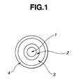
- FIG. 1 is a schematic sectional view of a burner such as may be used to form a porous silica matrix in the synthetic quartz glass production process of the invention.
- FIG. 2 illustrates the angle between the center axis of the porous silica matrix and the center axis of the stream of fluorine compound gas fed from the burner.
- FIG. 3 is a plot of the vacuum ultraviolet light transmittance by synthetic quartz glass produced under the conditions of Example 1 according to the invention.
- FIG. 4 is a plot of the vacuum ultraviolet light transmittance by synthetic quartz glass produced under the conditions of Comparative Example 1.
- the inventive process for producing fluorine-containing synthetic quartz glass comprises the steps of feeding a silica-forming raw material gas, hydrogen gas, oxygen gas and a fluorine compound gas from a burner to a reaction zone; flame hydrolyzing the silica-forming raw material gas in the reaction zone to form fine particles of fluorine-containing silica; depositing the silica fine particles on a rotatable substrate in the reaction zone so as to create a fluorine-containing porous silica matrix; and heating and vitrifying the porous silica matrix in a fluorine compound gas-containing atmosphere.
- fluorine doping is carried out during production of the porous silica matrix in such a way that the fluorine atom concentration increases from the outer periphery toward the center portion of the matrix. Fluorine doping is later carried out once again during vitrification of the matrix, at which time doping proceeds more readily on the outside than at the center.
- Quartz glass having a fluorine atom concentration higher than 2 wt % can easily be obtained by such a two-step doping process.
- quartz glass having a high and uniform concentration of fluorine can be achieved.
- This in turn makes it possible to produce synthetic quartz glass in which the formation of structural defects such as oxygen deficiency defects has been drastically reduced and which thus has an excellent tolerance to excimer laser radiation.
- the above process allows doping during vitrification to be concentrated on the outside of the matrix, enabling the vitrification of a high bulk density matrix.
- quartz glass is easier to uniformly dope when it has a lower density.
- doping is first carried out during vitrification.
- the bulk density at the surface rises during doping, bringing about a gradual decline in the doping rate.
- the result is a radial drop in the dopant concentration as the center of the matrix is approached.
- fluorine doping to a uniform and high concentration requires that a matrix having a low bulk density and a small diameter be gradually heated to the vitrification temperature, and fluorine doping carried out over an extended period of time.
- the process according to the present invention is able to vitrify in a short period of time a matrix having a higher bulk density and a larger diameter
- the porous silica matrix forming method used in the invention may be one already known to the art, and may be carried out in accordance with conventional conditions, such as the gas flow rate in the burner, and using as the silica-forming raw material gas a known organosilicon compound.
- chlorosilane compounds such as tetrachlorosilane (SiCl 4 ) and dimethyldichlorosilane ((CH 3 ) 2 SiCl 2 ), as well as silane and siloxane compounds of general formulas I to III below.
- R 1 and R 2 are each independently aliphatic monovalent hydrocarbon groups;
- R 3 is a hydrogen atom or an aliphatic monovalent hydrocarbon group;
- the letter m is at least 1, and preferably 1 or 2;
- the letter n is an integer from 0 to 3; and
- the letter p is an integer from 3 to 5.
- Illustrative examples of aliphatic monovalent hydrocarbon groups suitable as R 1 , R 2 or R 3 include C 1-4 alkyl groups such as methyl, ethyl, propyl, n-butyl and tert-butyl; C 3-6 cycloalkyl groups such as cyclohexyl; and C 2-4 alkenyl groups such as vinyl and allyl.
- silane compounds of above general formula I include Si(OCH 3 ) 4 , Si(OCH 2 CH 3 ) 4 and CH 3 Si(OCH 3 ) 3 .
- An exemplary siloxane compound of above general formula II is hexamethyldisiloxane.
- an alkoxysilane containing no chlorine is preferable for avoiding ultraviolet light absorption by Si-Cl bonds.
- fluorine compounds examples include tetrafluorosilane, trifluoromethane and tetrafluoromethane.
- the burner used here usually has a plurality of nozzles arranged concentrically. Use may be made of any known burner of this type which is capable of supporting flame hydrolysis by feeding to a reaction zone a silica-forming raw material gas and a fluorine compound gas from the center nozzle, feeding oxygen gas from a second nozzle located outside the center nozzle, and feeding oxygen gas and/or hydrogen gas from one or more nozzles located outside of the second nozzle.
- FIG. 1 shows a typical burner suitable for use in working the invention.
- a center tube nozzle 1 feeds a silica-forming raw material gas and a fluorine compound gas
- a first ring tube 2 also referred to herein as the "second nozzle” surrounding the center tube nozzle 1 feeds oxygen gas
- a second ring tube 3 surrounding the first ring tube 2 feeds hydrogen gas
- a third ring tube 4 surrounding the second ring tube 3 feeds oxygen gas.
- Use may be made of a plurality of burners, including one or more auxiliary burner, in which case the auxiliary burner may supply only an oxyhydrogen flame or may supply a fluorine compound gas.
- the angle between the stream of fluorine compound gas and the center axis of the porous silica matrix is preferable for the angle between the stream of fluorine compound gas and the center axis of the porous silica matrix to be large.
- an angle ⁇ of 120 to 150° is preferred.
- a burner 12 is adapted to feed a fluorine compound toward a porous silica matrix 11.
- the porous silica matrix 11 has a center axis A, and the stream of fluorine compound gas fed from the burner 12 has a center axis B oriented at an angle ⁇ to the center axis A of the porous silica matrix 11.
- center axis B should preferably intersect center axis A at the front end of the porous silica matrix 11.
- the porous silica matrix prefferably has a bulk density of at least 0.1 g/cm 3 , more preferably 0.1 to 0.7 g/cm 3 , and most preferably 0.3 to 0.7 g/cm 3 .
- the porous silica matrix formed in the process described above is vitrified in a high-temperature glassmaking furnace under a fluorine atmosphere.
- Vitrification may be carried out using a known method and conditions, such as heating and vitrifying in a mixed gas atmosphere composed of a fluorine compound gas and an inert gas to a temperature of 1,200 to 1,700°C.
- the fluorine compound gas may be selected from among such fluorine compounds as SiF 4 , CHF 3 and CF 4 .
- Suitable inert gases include helium, argon and nitrogen.
- the concentration of fluorine compound is preferably at least 0.01 vol %.
- the quartz glass is cooled to room temperature within the same glassmaking furnace by quenching, slow cooling or radiation cooling.
- a known method and known conditions may be used to carry out hydrogen heat treatment.
- Vitrification of the porous silica matrix in a fluorine atmosphere and subsequent hydrogen doping may be carried out as consecutive steps.
- the synthetic quartz glass produced by the above-described sequence of steps according to the invention has a hydroxyl group concentration of preferably not more than 0.002 wt %, and most preferably not more than 0.0001 wt %.
- the synthetic quartz glass produced by the inventive process has a fluorine atom concentration of preferably at least 0.01 wt %, more preferably at least 0.5 wt %, and most preferably at least 2 wt %.
- the synthetic quartz glass has a hydrogen atom concentration of preferably at least 1 ⁇ 10 17 molecules/cm 3 , more preferably at least 3 ⁇ 10 17 molecules/cm 3 , and most preferably at least 1 ⁇ 10 18 molecules/cm 3 .
- a porous silica matrix was produced by feeding from a burner 2.8 m 3 /h of hydrogen gas, 4.0 m 3 /h of oxygen gas, and both 1,000 g/h of tetramethoxysilane and 0.06 m 3 /h of SiF 4 as the silica-forming raw materials, and carrying out hydrolysis in an oxyhydrogen flame.
- the angle ⁇ between the center axis of the matrix and the center axis of the stream of SiF 4 gas fed from the burner was adjusted to 150°.
- the resulting porous silica matrix had a bulk density of 0.4 g/cm 3 .
- the porous silica matrix was heated in a SiF 4 atmosphere within a high-temperature glassmaking furnace to effect melting and vitrification, thereby forming a synthetic quartz glass.
- the SiF 4 gas was introduced into the furnace at a flow rate of 0.06 m 3 /h. Vitrification took 5 hours.
- the synthetic quartz glass produced under these conditions was then cut off, and fabricated into samples optically polished on both sides and having a diameter of 110 mm and a thickness of 6.3 mm.
- the fluorine atom concentration within the quartz glass was 2.3 to 2.4 wt % from the center to the outer periphery of the sample.
- the hydroxyl group concentration was 0 wt %.
- the transmittance of the sample to vacuum ultraviolet light was measured at the center and outer periphery of the sample. As shown in FIG. 3, the transmittance was very high within a wavelength range of 155 to 300 nm. No substantial difference was observed between the transmittance at the center of the sample and the transmittance at the outer periphery. Indeed, in FIG. 3, the plots of transmittance at the center and at the periphery overlap completely. Transmittance to 157.6 nm radiation, both at the center and the outer periphery of the sample, was 83%.
- a porous silica matrix was produced by feeding from a burner 2.5 m 3 /h of hydrogen gas, 3.5 m 3 /h of oxygen gas, and both 800 g/h of tetramethoxysilane and 0.04 m 3 /h of SiF 4 as the silica-forming raw materials, and carrying out hydrolysis in an oxyhydrogen flame.
- the angle ⁇ between the center axis of the matrix and the center axis of the stream of SiF 4 gas fed from the burner was adjusted to 130°.
- the resulting porous silica matrix had a bulk density of 0.5 g/cm 3 .
- the porous silica matrix was heated in a mixed gas atmosphere of SiF 4 and helium within a high-temperature glassmaking furnace to effect melting and vitrification, thereby forming a synthetic quartz glass.
- the SiF 4 gas and helium gas were introduced into the furnace at respective flow rates of 0.04 m 3 /h and 0.02 m 3 /h. Vitrification took 5 hours.
- the synthetic quartz glass produced under these conditions was then cut off, and fabricated into samples optically polished on both sides and having a diameter of 110 mm and a thickness of 6.3 mm.
- the fluorine atom concentration within the quartz glass was 2.0 to 2.1 wt % from the center to the outer periphery of the sample.
- the hydroxyl group concentration was less than 0.0001 wt %.
- the transmittance to vacuum ultraviolet light was measured at the center and outer periphery of the sample. No substantial difference was observed in the transmittances, which were good within a wavelength region of 155 to 300 nm.
- a porous silica matrix was produced by feeding hydrogen gas, oxygen gas, and both tetramethoxysilane and SiF 4 as the silica-forming raw materials from a burner under the same gas conditions as in Example 1.
- the angle ⁇ between the center axis of the matrix and the center axis of the stream of SiF 4 gas fed from the burner was adjusted to 150°.
- the resulting porous silica matrix had the same bulk density of 0.4 g/cm 3 as in Example 1.
- the porous silica matrix was melted and vitrified under the same conditions as in Example 1, and the resulting synthetic quartz glass was heat-treated at 500°C for 100 hours in a mixed gas atmosphere of hydrogen and helium. During heat treatment, the H 2 concentration was 3 vol % and the pressure was 10 MPa.
- the synthetic quartz glass produced under these conditions was then cut off, and fabricated into samples optically polished on both sides and having a diameter of 110 mm and a thickness of 6.3 mm.
- the fluorine atom concentration within the quartz glass was 2.3 to 2.4 wt % from the center to the outer periphery of the sample.
- the hydroxyl group concentration was 0 wt %.
- the transmittance to vacuum ultraviolet light was measured at the center and outer periphery of the sample. No substantial difference was observed in the transmittances, which were good within a wavelength region of 155 to 300 nm. Transmittance to 157.6 nm radiation, both at the center and outer periphery of the sample, was 85%, which was higher than in Example 1.
- a porous silica matrix was produced by feeding hydrogen gas, oxygen gas, and tetramethoxysilane as the silica-forming raw material from a burner under the same gas conditions as in Example 1. SiF 4 was not used. The angle ⁇ between the center axis of the matrix and the center axis of the stream of silica-forming raw material gas fed from the burner was adjusted to 150°. The resulting porous silica matrix had the same bulk density of 0.4 g/cm 3 as in Example 1.
- the porous silica matrix was heated in a SiF 4 atmosphere within a high-temperature glassmaking furnace to effect melting and vitrification, thereby forming a synthetic quartz glass.
- the SiF 4 gas was introduced into the furnace at a flow rate of 0.06 m 3 /h. Vitrification took 5 hours.
- the synthetic quartz glass produced under these conditions was then cut off, and fabricated into samples optically polished on both sides and having a diameter of 110 mm and a thickness of 6.3 mm.
- the fluorine atom concentration within the quartz glass ranged from 1.4 to 2.1 wt % from the center to the outer periphery of the sample, indicating a very large difference between the center and peripheral portions.
- the hydroxyl group concentration was less than 0.0001 wt %.
- the transmittance of the sample to vacuum ultraviolet light was measured at the center and outer periphery of the sample. As shown in FIG. 4, the transmittance was relatively high within a wavelength range of 155 to 300 nm, but a difference was observed between the transmittance at the center of the sample and the transmittance at the periphery. The difference in transmittance was particularly large in the vacuum ultraviolet region at wavelengths smaller than 165 nm. The transmittance to 157.6 nm radiation was 73% in the center portion, and 78% at the outer periphery.
- the inventive process enables the low-cost manufacture of synthetic quartz glass having a higher and more uniform transmittance to light in the vacuum ultraviolet region than has hitherto been achieved.
Landscapes
- Engineering & Computer Science (AREA)
- Multimedia (AREA)
- Signal Processing (AREA)
- Compression, Expansion, Code Conversion, And Decoders (AREA)
- Color Television Systems (AREA)
- Compression Or Coding Systems Of Tv Signals (AREA)
- Glass Compositions (AREA)
Abstract
Description


Claims (5)
- A process for producing synthetic quartz glass, comprising the steps of:feeding a silica-forming raw material gas, hydrogen gas, oxygen gas and a fluorine compound gas from a burner to a reaction zone,flame hydrolyzing the silica-forming raw material gas in the reaction zone to form fine particles of fluorine-containing silica,depositing the silica fine particles on a rotatable substrate in the reaction zone so as to create a fluorine-containing porous silica matrix, andheating and vitrifying the porous silica matrix in a fluorine compound gas-containing atmosphere.
- The synthetic quartz glass production process of claim 1 in which, during formation of the porous silica matrix, the silica matrix and the stream of fluorine compound gas are oriented such that their respective center axes describe an angle therebetween of 120 to 150°.
- The synthetic quartz glass production process of claim 1, further comprising the step of heat treating the synthetic quartz glass in a hydrogen gas atmosphere.
- The synthetic quartz glass production process of claim 1, wherein the porous silica matrix has a bulk density of at least 0.1 g/cm3.
- A synthetic quartz glass produced by the process of claim 1, which synthetic quartz glass has a hydroxyl group concentration of at most 0.002% by weight and a fluorine atom concentration of at least 0.01% by weight.
Applications Claiming Priority (2)
| Application Number | Priority Date | Filing Date | Title |
|---|---|---|---|
| JP2000236493 | 2000-08-04 | ||
| JP2000236493 | 2000-08-04 |
Publications (3)
| Publication Number | Publication Date |
|---|---|
| EP1178688A2 true EP1178688A2 (en) | 2002-02-06 |
| EP1178688A9 EP1178688A9 (en) | 2002-04-10 |
| EP1178688A3 EP1178688A3 (en) | 2003-07-30 |
Family
ID=18728527
Family Applications (1)
| Application Number | Title | Priority Date | Filing Date |
|---|---|---|---|
| EP20010306669 Withdrawn EP1178688A3 (en) | 2000-08-04 | 2001-08-03 | Image decoding device and image decoding method |
Country Status (3)
| Country | Link |
|---|---|
| US (1) | US6920176B2 (en) |
| EP (1) | EP1178688A3 (en) |
| JP (1) | JP2002118853A (en) |
Families Citing this family (8)
| Publication number | Priority date | Publication date | Assignee | Title |
|---|---|---|---|---|
| US7280595B1 (en) | 2003-10-21 | 2007-10-09 | Redrock Semiconductor, Ltd. | Post-inverse-quantization AC prediction with a unified variable-length-decoding and inverse-quantization stage |
| JP2005318559A (en) * | 2004-03-30 | 2005-11-10 | Matsushita Electric Ind Co Ltd | Inverse prediction apparatus and decoding apparatus using the same |
| US20050232350A1 (en) * | 2004-03-30 | 2005-10-20 | Mana Hamada | Inverse prediction apparatus and decoding apparatus using the same |
| JP4502203B2 (en) | 2005-03-17 | 2010-07-14 | ルネサスエレクトロニクス株式会社 | Image encoding apparatus and image decoding apparatus |
| JP2007214641A (en) * | 2006-02-07 | 2007-08-23 | Seiko Epson Corp | Program for causing a computer to execute an encoding device, a decoding device, an image processing device, and an image processing method |
| JP2007259247A (en) * | 2006-03-24 | 2007-10-04 | Seiko Epson Corp | Encoding device, decoding device, data processing system |
| JP4802928B2 (en) * | 2006-08-09 | 2011-10-26 | ソニー株式会社 | Image data processing device |
| WO2008136164A1 (en) * | 2007-04-23 | 2008-11-13 | Panasonic Corporation | Decoding circuit, decoding method, and image reproduction device |
Family Cites Families (10)
| Publication number | Priority date | Publication date | Assignee | Title |
|---|---|---|---|---|
| JP3012698B2 (en) * | 1991-01-29 | 2000-02-28 | オリンパス光学工業株式会社 | Image data encoding apparatus and encoding method |
| US5828421A (en) | 1994-10-11 | 1998-10-27 | Hitachi America, Ltd. | Implementation efficient digital picture-in-picture decoding methods and apparatus |
| US5596376A (en) | 1995-02-16 | 1997-01-21 | C-Cube Microsystems, Inc. | Structure and method for a multistandard video encoder including an addressing scheme supporting two banks of memory |
| JPH09107547A (en) * | 1995-10-09 | 1997-04-22 | Hitachi Ltd | Compressed video data amount reduction device, compressed video data amount reduction system, and compressed video data amount reduction method |
| ES2171377T3 (en) | 1996-05-28 | 2002-09-16 | Matsushita Electric Industrial Co Ltd | DEVICE FOR PREDICTION AND DECODING OF IMAGE. |
| US5844608A (en) | 1996-12-12 | 1998-12-01 | Thomson Consumer Electronics, Inc. | Picture element processor for a memory management system |
| US6347116B1 (en) * | 1997-02-14 | 2002-02-12 | At&T Corp. | Non-linear quantizer for video coding |
| JP4214562B2 (en) * | 1998-06-26 | 2009-01-28 | ソニー株式会社 | Decoding device |
| KR100281967B1 (en) * | 1998-08-31 | 2001-02-15 | 전주범 | Image coding apparatus using spatial correlation and method thereof |
| JP2000341688A (en) * | 1999-05-31 | 2000-12-08 | Ando Electric Co Ltd | Decision device for moving image communication quality |
-
2001
- 2001-08-01 JP JP2001233146A patent/JP2002118853A/en active Pending
- 2001-08-02 US US09/921,453 patent/US6920176B2/en not_active Expired - Fee Related
- 2001-08-03 EP EP20010306669 patent/EP1178688A3/en not_active Withdrawn
Also Published As
| Publication number | Publication date |
|---|---|
| JP2002118853A (en) | 2002-04-19 |
| US20020054709A1 (en) | 2002-05-09 |
| EP1178688A3 (en) | 2003-07-30 |
| EP1178688A9 (en) | 2002-04-10 |
| US6920176B2 (en) | 2005-07-19 |
Similar Documents
| Publication | Publication Date | Title |
|---|---|---|
| US5958809A (en) | Fluorine-containing silica glass | |
| US5474589A (en) | UV light-permeable glass and article comprising the same | |
| EP0546196B1 (en) | Synthetic quartz glass optical member for excimer laser and production thereof | |
| US8650912B2 (en) | Burner and method for the manufacture of synthetic quartz glass | |
| EP0878451A1 (en) | Synthetic silica glass optical member and method of manufacturing the same | |
| US20080141717A1 (en) | Burner for the Manufacture of Synthetic Quartz Glass | |
| US20100179047A1 (en) | Optical member comprising tio2-containing silica glass | |
| JP4158009B2 (en) | Synthetic quartz glass ingot and method for producing synthetic quartz glass | |
| EP1188723B1 (en) | Synthetic quartz glass and method of production | |
| EP1067096B1 (en) | Quartz glass members for excimer laser, and their method of manufacture | |
| US20060107693A1 (en) | Method for the production of synthetic silica glass | |
| US6807823B2 (en) | Fluorine-containing glass | |
| EP1127857B1 (en) | Fluorine-containing synthetic quartz glass and method of production | |
| EP1178688A2 (en) | Image decoding device and image decoding method | |
| EP1112973B1 (en) | Process for producing a quartz glass product and the product so produced | |
| EP1219571B1 (en) | process for producing a synthetic quartz glass article | |
| JP3796653B2 (en) | Fluorine-containing synthetic quartz glass and method for producing the same | |
| JP4496421B2 (en) | Method for producing synthetic quartz glass | |
| JP2002255577A (en) | Synthetic quartz glass member and method of manufacturing the same | |
| JP2002154827A (en) | Manufacturing method of synthetic quartz glass | |
| JP2002308630A (en) | Manufacturing method of synthetic quartz glass | |
| JP2001322820A (en) | Fluorine-containing synthetic quartz glass and method for producing the same |
Legal Events
| Date | Code | Title | Description |
|---|---|---|---|
| PUAI | Public reference made under article 153(3) epc to a published international application that has entered the european phase |
Free format text: ORIGINAL CODE: 0009012 |
|
| AK | Designated contracting states |
Kind code of ref document: A2 Designated state(s): AT BE CH CY DE DK ES FI FR GB GR IE IT LI LU MC NL PT SE TR |
|
| AX | Request for extension of the european patent |
Free format text: AL;LT;LV;MK;RO;SI |
|
| PUAL | Search report despatched |
Free format text: ORIGINAL CODE: 0009013 |
|
| AK | Designated contracting states |
Designated state(s): AT BE CH CY DE DK ES FI FR GB GR IE IT LI LU MC NL PT SE TR |
|
| AX | Request for extension of the european patent |
Extension state: AL LT LV MK RO SI |
|
| 17P | Request for examination filed |
Effective date: 20031009 |
|
| AKX | Designation fees paid |
Designated state(s): DE FR GB |
|
| 17Q | First examination report despatched |
Effective date: 20040315 |
|
| RAP1 | Party data changed (applicant data changed or rights of an application transferred) |
Owner name: PANASONIC CORPORATION |
|
| STAA | Information on the status of an ep patent application or granted ep patent |
Free format text: STATUS: THE APPLICATION IS DEEMED TO BE WITHDRAWN |
|
| 18D | Application deemed to be withdrawn |
Effective date: 20110301 |