EP1178505A1 - Mécanisme de manoeuvre à chaine de traction pour un appareillage électrique de coupure haute tension - Google Patents
Mécanisme de manoeuvre à chaine de traction pour un appareillage électrique de coupure haute tension Download PDFInfo
- Publication number
- EP1178505A1 EP1178505A1 EP01410088A EP01410088A EP1178505A1 EP 1178505 A1 EP1178505 A1 EP 1178505A1 EP 01410088 A EP01410088 A EP 01410088A EP 01410088 A EP01410088 A EP 01410088A EP 1178505 A1 EP1178505 A1 EP 1178505A1
- Authority
- EP
- European Patent Office
- Prior art keywords
- drive shaft
- end member
- shaft
- energy
- accumulator
- Prior art date
- Legal status (The legal status is an assumption and is not a legal conclusion. Google has not performed a legal analysis and makes no representation as to the accuracy of the status listed.)
- Granted
Links
- 230000007246 mechanism Effects 0.000 title claims abstract description 48
- 230000005540 biological transmission Effects 0.000 claims abstract description 69
- 230000008878 coupling Effects 0.000 claims description 15
- 238000010168 coupling process Methods 0.000 claims description 15
- 238000005859 coupling reaction Methods 0.000 claims description 15
- 230000007935 neutral effect Effects 0.000 claims description 14
- 238000004146 energy storage Methods 0.000 claims description 9
- 238000005381 potential energy Methods 0.000 claims description 5
- 238000013016 damping Methods 0.000 claims description 4
- 239000013536 elastomeric material Substances 0.000 claims description 3
- 238000005086 pumping Methods 0.000 description 18
- 230000009467 reduction Effects 0.000 description 11
- 238000009825 accumulation Methods 0.000 description 7
- 230000010355 oscillation Effects 0.000 description 7
- 230000035939 shock Effects 0.000 description 7
- 241001272720 Medialuna californiensis Species 0.000 description 5
- 230000000694 effects Effects 0.000 description 5
- 239000000463 material Substances 0.000 description 5
- 230000009471 action Effects 0.000 description 3
- 230000008901 benefit Effects 0.000 description 3
- 230000006835 compression Effects 0.000 description 3
- 238000007906 compression Methods 0.000 description 3
- 229920001971 elastomer Polymers 0.000 description 2
- 239000000806 elastomer Substances 0.000 description 2
- 238000003780 insertion Methods 0.000 description 2
- 230000037431 insertion Effects 0.000 description 2
- 230000000717 retained effect Effects 0.000 description 2
- 230000002441 reversible effect Effects 0.000 description 2
- 125000006850 spacer group Chemical group 0.000 description 2
- 230000001052 transient effect Effects 0.000 description 2
- 238000012800 visualization Methods 0.000 description 2
- 238000004804 winding Methods 0.000 description 2
- 241001080024 Telles Species 0.000 description 1
- 238000010521 absorption reaction Methods 0.000 description 1
- 230000009977 dual effect Effects 0.000 description 1
- 230000005489 elastic deformation Effects 0.000 description 1
- 239000002184 metal Substances 0.000 description 1
- 238000012986 modification Methods 0.000 description 1
- 230000004048 modification Effects 0.000 description 1
- 230000002028 premature Effects 0.000 description 1
- 230000000284 resting effect Effects 0.000 description 1
Images




Classifications
-
- H—ELECTRICITY
- H01—ELECTRIC ELEMENTS
- H01H—ELECTRIC SWITCHES; RELAYS; SELECTORS; EMERGENCY PROTECTIVE DEVICES
- H01H3/00—Mechanisms for operating contacts
- H01H3/22—Power arrangements internal to the switch for operating the driving mechanism
- H01H3/30—Power arrangements internal to the switch for operating the driving mechanism using spring motor
-
- H—ELECTRICITY
- H01—ELECTRIC ELEMENTS
- H01H—ELECTRIC SWITCHES; RELAYS; SELECTORS; EMERGENCY PROTECTIVE DEVICES
- H01H3/00—Mechanisms for operating contacts
- H01H3/22—Power arrangements internal to the switch for operating the driving mechanism
- H01H3/30—Power arrangements internal to the switch for operating the driving mechanism using spring motor
- H01H2003/3084—Kinetic energy of moving parts recuperated by transformation into potential energy in closing or opening spring to be used in next operation
-
- H—ELECTRICITY
- H01—ELECTRIC ELEMENTS
- H01H—ELECTRIC SWITCHES; RELAYS; SELECTORS; EMERGENCY PROTECTIVE DEVICES
- H01H3/00—Mechanisms for operating contacts
- H01H3/32—Driving mechanisms, i.e. for transmitting driving force to the contacts
- H01H3/36—Driving mechanisms, i.e. for transmitting driving force to the contacts using belt, chain, or cord
-
- H—ELECTRICITY
- H01—ELECTRIC ELEMENTS
- H01H—ELECTRIC SWITCHES; RELAYS; SELECTORS; EMERGENCY PROTECTIVE DEVICES
- H01H3/00—Mechanisms for operating contacts
- H01H3/60—Mechanical arrangements for preventing or damping vibration or shock
Definitions
- the invention relates to a mechanism for operating a high cut-off device voltage, in particular of a circuit breaker, of the type comprising an energy accumulator potential elastic, a drive shaft intended to drive at least one contact mobile circuit breaker via kinematic transmission, and a flexible link traction, of the traction chain or cable type, having two ends, one connected to the energy accumulator, and the other to the transmission shaft, the flexible link passing through a intermediate return pulley.
- attachment and gear reduction members are parts very sensitive to unwanted mechanical vibrations, so that a device generating shocks would be exposed to risks of inadvertent tripping.
- a such a device does not allow rapid resetting of the accumulator spring at the end of opening race.
- Document EP 238 847 relates explicitly to an actuation mechanism a very high voltage circuit breaker, therefore a fast-moving and energy-saving mechanism high kinetics.
- a first spring connected to the transmission shaft via a first chain
- a second spring connected to the transmission shaft via a second chain.
- the chains are arranged so that when the two springs are loaded, the chains are located on either side of the axis of rotation of the drive shaft. So the couple exerted by the first spring is partially compensated by the torque exerted by the second spring.
- the armed position is therefore a position close to an unstable equilibrium.
- the second spring exceeds its neutral position, so that the two springs become motors. No special provision is made for limit the vibrations generated by the discharge of the storage springs.
- the invention aims to provide a mechanism of the above type, which allows a very fast actuation of high voltage electrical switchgear having a high electrical power, therefore a significant mobile mass. More precisely, the invention aims to reduce the vibrations generated by the mechanism during closing switchgear contacts. It also aims to facilitate the rapid rearmament of the energy accumulator when it reaches its discharged position.
- the auxiliary energy storage means has a dual function. On the one hand, it amortizes the shock transmitted by the accumulator to the chassis when passing through the bottom dead center. On the other hand, the energy returned makes it possible to speed up the rearming of the accumulator. energy.
- the mechanism further comprises a wheel coupling free connecting the drive shaft to the chassis, allowing the rotation of the shaft transmission in a working direction and preventing rotation of the transmission shaft in an opposite direction.
- a closing lock is capable of locking the drive shaft in an armed position, corresponding to the charged position of the energy accumulator.
- a switching shaft is able to be kinematically connected to at least one control member movable contact of the electrical switchgear.
- a means of coupling integral with the drive shaft is suitable for coupling the drive shaft with the shaft when the drive shaft reaches a coupling position and at disconnect the drive shaft from the switching shaft when the drive shaft transmission reaches a decoupling position, the coupling position being located between the armed position and the bottom dead center position, in the working direction, the uncoupling position being located between the coupling position and the position of bottom dead center, in the direction of work.
- the transmission shaft has such a moment of inertia that when the closing latch releases the drive shaft, the first member end of the energy accumulator changes from its charged position to its position discharged and drives the drive shaft from its armed position to its position bottom dead center, then the drive shaft continues to rotate from its neutral position dead down in the direction of its arming position in the working direction by driving the first end member from its discharged position to its charged position.
- the tree of transmission then constitutes a flywheel which has a driving role after passing through the bottom dead center. Resetting the device is then much faster. This arrangement is particularly advantageous for apparatus of dimensions important. Indeed, the mass and the moment of inertia of the drive shaft are dimensioned according to the maximum torque to be transmitted to the contact members of switchgear.
- the moment of inertia of the drive shaft increases with the dimensions of the contact members.
- the mechanism makes it possible to recover part of kinetic energy of the shaft to partially rearm the springs.
- the engines that complete the rearmament then have less energy to supply, and can be sized differently.
- the flexible link has a longitudinal elasticity such that it undergoes a elastic elongation when the first end member of the energy accumulator overtravel.
- the flexible link is a chain of traction. It can also be a cable or a rope.
- the pulley makes it possible to partially decouple the vibratory modes of the shaft on the one hand and on the other hand, part of the forces transmitted by the flexible link being taken up by the pulley support shaft.
- the pulley allows a bevel gear which limits the overall size of the mechanism. Since the transmission of movement of the energy accumulator to the tree is done via a link flexible, the relative positioning of the first end of the energy accumulator and the idler pulley need not be very precise.
- the second part of the flexible link makes an angle of about 135 ° with the first part of the flexible link.
- the energy accumulator comprises: a second end member, at least one spring banded between the first end member and the second end member, a telescopic connecting member comprising a guide secured to one of the first and second end members, and a slide secured to the other of the first and second end members, the slide being movable in translation relative to the guide.
- the chassis has at least one support stop, the spring tending to urge the second end member to bear against the support stop.
- the telescopic connection comprises an end of travel stop disposed between the guide and the slider in such a way that when the first end member passes from its position loaded in its unloaded position, the end stop comes between the guide and the slider before the first end member reaches its unloaded position, and that when the first end member continues its travel beyond its unloaded position, the first movable member drives the second movable member.
- the stop limit switch is a damping stop capable of absorbing kinetic energy when the first end member passes from the intermediate position or the end stop between the guide and the slide in the unloaded position.
- Vibrations induced by the spring of the energy accumulator are absorbed by the stop damping while the first end member overtraveling, that is to say at a time when neither the first nor the second end member of the accumulator of energy are only in contact with the chassis.
- the drive shaft is linked to the chassis via a first freewheel.
- the mechanism further comprises: at least one electric motor connected to the drive shaft via a second freewheel; a device for control able to detect the passage of the drive shaft through a position predetermined and to drive the electric motor, so that when the shaft of transmission exceeds its low neutral position, the electric motor starts to drive the drive shaft before the speed of the drive shaft cancels.
- the auxiliary energy storage means comprises at at least one stud comprising an elastomeric material. We thus very simply cumulate the energy accumulation and vibration damping functions sought.
- a mechanism for operating an electrical apparatus high voltage shutdown is mainly composed of an energy accumulator closure 10, an arming subset 12 and a switching shaft 14, connected between them by means of a transmission shaft 16 and supported by a chassis 18.
- the switching shaft 14 is intended to be kinematically connected to one or more movable contact members of the switchgear, so as to drive them reversibly from an open position to a closed position.
- the chassis 18 comprises two parallel main plates 20, 22, fixed to each other by spacers 24. Some elements of the mechanism are located between the plates 20, 22 of so that to visualize them, it was necessary to represent the dashed plate 20 on the view in FIG. 1 and to show the dashed plate 22 in the same way in FIG. 2. An intermediate plate 23 is held by spacers between the plates 20 and 22.
- the transmission shaft 16 and the switching shaft 14 are pivotally mounted on guide bearings (not shown) fixed to the plates 20, 22 of the chassis 18, so that their axes of rotation are parallel to each other and perpendicular to the planes of plates 20, 22 and 23.
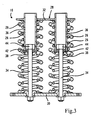
- the energy accumulator 10, shown in section in FIG. 3, comprises two pairs of accumulation springs 26 with flanges, retained by a stiffening structure 28.
- This structure is composed of a first end plate 30 and a second plate end 32, connected to each other by means of a guide link telescopic.
- the telescopic link is formed by two parallel guides, comprising each a rod 34 integral with the first end plate 30, and sliding in a tube 36 secured to the second end 32.
- Each tube is provided with a bottom 38 pierced an axial guide hole allowing the free translation of the corresponding rod 34.
- a stop 42 consisting of a washer of elastomer material surmounted by a washer metal, rests on this bottom 38.
- each rod 34 is inserted into the tube 36 corresponding and provided with a nut 44 forming a shoulder capable of coming in contact with the corresponding stop 42.
- the telescopic connection obtained allows translational movement of the first end plate 30 relative to the second end plate 28, along a geometric axis of translation parallel to the rods 34. This movement is limited in the direction of the distance by the meeting of the shoulder constituted by the nut 44, with the elastomer end stop 42.
- the coil springs 26 are supported by their ends on the end plates 30, 32 and are mounted coaxially outside of each of the two parallel guides.
- the springs 26 are compression springs, that is to say springs which increase their potential energy when compressed and which provide work during their extension.
- the energy accumulator 10 is dimensioned in such a way that when the nuts 44 are in contact with the end stops 42, the springs 26 are completely relaxed and just in contact with the two end plates 30, 32. This state of the energy accumulator 10 will be said hereinafter discharged state.
- Two identical windows 50 of generally rectangular shape, more particularly visible in FIGS. 4 and 7, are formed in the plates of the chassis 20, 22 and arranged opposite one from the other.
- Each rectangular window 50 defines two large lateral sides 52 and two small horizontal sides 54, 56, one lower (54), the other upper (56).
- staves 58 are arranged side by side along the short upper side of each window.
- the four spans 58 together define a geometric support plane for the second end plate 32 of the energy accumulator 10, this plane being perpendicular to the plates 20, 22 of the chassis.
- the end plates 30, 32 of the energy accumulator are provided with ribs of positioning 60, cooperating with the windowsills, so as to produce a guiding the two end plates 30, 32, allowing their translation along an axis geometric perpendicular to the geometric support plane defined by the spans 58.
- the rods 34 remain substantially perpendicular to the geometric plane support, whatever the movement of the energy accumulator 10 in the windows 50.
- Guidance is ensured with a play of a few millimeters.
- the long sides 52 of the two windows 50 are provided with two mounting grooves 62, allowing lateral insertion of the sub-assembly formed by the energy accumulator 10 during assembly of the mechanism.
- the movement of the first end plate 30 is limited by four studs 64 in elastomeric material, which together define a geometric plane of contact with the plate 30. These studs 64 form end-of-travel stops for the first plate end 30.
- the studs 64 are screwed into nuts 66 welded to the edge of the small lower sides 54 of windows 50, and stopped by locknuts 68.
- the accumulator 10 is assembled as a sub-assembly outside the chassis, under the shape shown in Figure 3.
- the distance between the upper grooves 62 and lower windows corresponds to the distance between the two end plates 30, 32 of the stiffening structure 28 of the accumulator 10 in its discharged state.
- the studs 64 are screwed in fully, which has the effect of lowering the contact plane previously mentioned, below the level of the lower groove 62. It is then possible to insert the accumulator 10 laterally at the through windows 50. Once the accumulator 10 is inserted, the pads 64 are partially unscrewed, so as to gradually raise the accumulator until the plate upper 32 is in contact with the surfaces 58 and the lower plate 30 is in contact studs 64, the accumulator 10 remaining in its discharged state. Finally, the locknuts 68 are positioned so as to block the studs 64 in position.
- the distance between the geometric support plane defined by the spans 58 on the one hand, and the plane geometric contact defined by the pads 64 on the other hand, is substantially equal to the distance between the first plate 30 and the second plate 32 when the accumulator is in its discharged state.
- the first end plate 30 projects through the windows 50 on either side of the space delimited by the plates 20, 22 of the chassis 18.
- the two projecting parts of the plate 30 are each provided with a pair of oblong through holes.
- the transmission shaft 16 is provided with two identical parallel cranks 70, 72, visible in Figures 1 and 2.
- the cranks 70, 72 are located on either side of the portion of space delimited by the plates 20, 22 of the chassis.
- Each crank is provided two flat cheeks perpendicular to the axis of rotation of the transmission shaft 16, forming between them a groove 74.
- the two flat cheeks support an eccentric pin 76, part of which is located in the throat.
- a flexible kinematic connection between the energy accumulator 10 and the shaft of transmission 16 is established by means of two identical traction chains 80, which are located on either side of the space delimited by the two plates 20, 22 of the chassis.
- the chains 80 have been shown in a simplified manner in the figures, but they comprise preferably articulated links.
- the assembly of the two chains 80 is symmetrical relative to a median geometric plane parallel to the plates 20, 22 of the chassis 18.
- Each traction chain 80 is stretched between one of the cranks 70 and the projecting part of the first plate 30 located on the same side of the plates 20, 22 of the chassis.
- One end of the chain 80 is provided with an eyelet 82 forming a socket which pivots on the eccentric axis 76 of the crank. In FIG. 2, the eyelet is shown in dotted lines, so as to allow view the axis 76.
- the other end of the chain 80 is provided with a double eyelet 84, which is inserted into the pair of through oblong holes and stopped by a pin 86.
- the chain 80 passes through an intermediate pulley 90, mounted idly on a supported axis 92 by the chassis 18.
- Part 94 of the chain, stretched between the pulley and the first plate end, is parallel to the axis of translation of the first plate 30, therefore parallel to the times to the geometric axis defined by the telescopic guide link of the structure stiffening 28 of the energy accumulator 10 and to the guide surfaces formed by the edges of the long sides 52 of the windows 50.
- Another part 96 of the chain is stretched between the pulley and the axle 76.
- Each chain 80 works in a plane parallel to the plates 20, 22 of the chassis. It exists two positions of the mechanism in which the geometric plane containing the axis geometric rotation of the drive shaft 16 and the pivot axis 76 of the sleeve 82 becomes tangent to the periphery of the pulley 90 and to the part 96 of the chain.
- the socket 82 is located between the shaft 16 and the pulley 90, which corresponds to a bottom dead center of the transmission shaft 16, that is to say to a stable equilibrium position.
- the transmission shaft 16 is between the bush 82 and the pulley 90, which corresponds to a top dead center of the shaft 16, that is to say at an unstable equilibrium position.
- the length of the two chains 80 is such as when the drive shaft 16 is placed in its bottom dead center position - and stopped in this position -, and that the accumulator 10 is in its discharged state, the first end plate 30 resting on the studs 64, the two chains 80 are only subject to very low tension, in fact the tension just necessary to keep them in the pulleys 90.
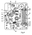
- the central part of one of the axes 76 further constitutes a roller 98 which cooperates with a cam 100 of a starting lever 102.
- the lever start 102 is supported by a pivot 104 mounted on the chassis 18 and is recalled by a starting spring 106, bandaged between a free end of the lever 102 and a cleat mounted on the chassis.
- This sub-assembly constitutes a starting device.
- the roller 98 Shortly before arriving at top dead center position, for example 1 degree from this position, in a so-called position at the start of treatment, the roller 98 passes the top 108 of the cam 100, so that the starting lever 102, recalled by the starting spring 106, becomes engine by relative to the roller 98. The starting lever 102 remains engine until the roller 98 loses contact with the cam 100, approximately 5 degrees after the top dead center position, in a so-called end of care position.
- the arming sub-assembly 12 a detail of which is shown in FIG. 5, comprises a ratchet wheel 110, integral with the transmission shaft 16, and which cooperates with five pawls, namely: two pawls 112, 113 mounted on a manual pumping lever 118, two pawls 114, 115 mounted on a stop support 120 secured to the chassis 18, and a pawl 116 mounted on a motorized pumping lever 122.
- Each pawl is returned to a position of coupling with the ratchet wheel, by a torsion spring.
- the lever manual pumping 118 and motorized pumping lever 122 are both fitted pivoting on the drive shaft 116.
- the pawls 112, 113, 114, 115, 116 and the wheel ratchet make freewheel couplings between the transmission shaft 16 and the lever manual pumping 118, between the transmission shaft 16 and the motorized pumping lever 122 and between the transmission shaft 16 and the chassis 18.
- a free end of the manual pump lever 118 is connected to an input shaft 124 by via a reduction lever 126 pivoting relative to the chassis around a pivot 128, and two transmission rods 130, 132 connecting the transmission lever 126 on the one hand to a crank 134 of the input shaft 124 and on the other hand to the pumping lever manual 118.
- the end of the input shaft 124 has a key 134 allowing inserting a removable crank 136 visible in FIG. 1.
- the reduction lever 126 When an operator turns crank 136 by one turn, the reduction lever 126 performs an oscillation which is transmitted with a gear reduction to the manual pump lever 118, so that the manual pump lever 118 makes an angular oscillation - back and forth - of one amplitude corresponding to about a tooth and a half of the ratchet wheel 110.
- the manual pump lever 118 is designed as an emergency accessory. In use normal, it is in a rest position, pressing against a limit stop 138 of support 120.
- a free end of the motorized pumping lever 122 is provided with a cooperating roller 140 with a cam 142 keyed onto an output shaft 144 of a geared motor group 146, visible in FIG. 1.
- the geared motor group 146 comprises two electric motors 148, 150 driving a gear train 152 connected to the output shaft 144.
- a spring of recall 154 tends to recall the motorized pumping lever 116 in the opposite direction of clockwise in Figure 5.
- the motorized pumping lever 116 makes a back and forth oscillation of a angular amplitude corresponding to approximately 3.8 teeth of the ratchet wheel 110.
- the two pawls 112, 113 supported by the manual pumping lever 118 form between them an angle corresponding to 4.5 teeth of the ratchet wheel 110.
- the two pawls 114, 115 of the stop support 120 form an angle between them corresponding to 4.5 teeth of the ratchet wheel 110.
- the pawl 114 of the stop support forms with the adjacent pawl 113 of the manual pump lever 118 an angle corresponding to 5.25 teeth of the ratchet wheel.
- the ratchet wheel 110 starts to rotate in the opposite direction to that permitted by the pawls, it cannot cover an angle greater than that corresponding to 0.25 teeth without being taken over and stopped by one of the pawls.
- the ratchet wheel 110 is provided with a toothless sector 158, which is at the height of the pawl 116 supported by the motorized pump lever 122 when the drive shaft 16 is near the top dead center.
- a toothless sector 158 When the toothless sector 158 is in opposite the motorized pumping lever 122, it can perform a full oscillation at empty.
- the drive shaft 16 further supports and so classic a drive cam 160 cooperating with a roller 162 mounted on a crank 164 fixed to the switching shaft 14.
- the cam has a circular part non-driving and a driving part.
- the switching shaft 14 is kinematically connected to at least one movable contact member 166 of the switchgear, via a kinematic chain 168 that has been shown purely schematically.
- the switching shaft can simultaneously drive several contacts mobile, each corresponding to a pole of the apparatus.
- a classic configuration has three poles, corresponding to the three phases of a three-phase electrical network.
- the shaft 14 oscillates between an open position and a closed position forming an angle of 55 ° with each other.
- a trigger 172 is pivotally mounted on the crank 164 of the switching shaft 14.
- a spring 174 tends to drive the trigger 172 projecting from the crank 164.
- the trigger 172 forms a spout which cooperates with an intermediate roller 176 carried by a lever reduction gear 178 which forms an intermediate lock.
- the leverage 178 pivots about an axis 180 and further comprises a second roller 182 cooperating with a rotary opening lock 184.
- the opening lock 184 is returned to the position of locked by a spring (not shown), and driven to an unlocked position by an opening control lock 186.
- the axes geometric rotation of the three locks are parallel to each other and parallel to the axes geometric rotation of the transmission shafts 16 and switching 14.
- Each of the three locks is provided with a return spring (not shown), which tends to return it in the anti-clockwise in Figure 6 to a locked position.
- the opening control lock 186 the structure of which is visible in FIG. 7, comprises a material axis 210 having a half-moon cutout 212 cooperating with the opening latch 184, and two control cranks 214, 216.
- One end 218 of the axis 210 is mounted in a bearing supported by the intermediate plate 23 of the chassis, while a second bearing 222 is mounted on the plate 20.
- the control crank 216 is actuated by an electromechanical relay 190 for opening control at electromagnet, provided with a plunger 192 with axial movement.
- the control crank 214 is actuated by a stud 224 supported by a rotary control lever 226.
- the lever 226 has a flywheel 228 projecting in front of the plate 20, so as to be accessible by an operator, this steering wheel being secured to a material axis of rotation 230 one end 232 of which is guided in rotation in the plate 20.
- the drive cam 160 is also provided with an eccentric pin, carrying a roller 194 intended to cooperate with a rotary closing lock 196.
- the closing locks 196 and closing control 200 are pivotally mounted, perpendicular to the plate 20, therefore parallel to the axes of rotation of the transmission and switching shafts 16 14. They are both recalled by recall springs which tend to recall them in the counterclockwise in Figure 6, toward their locked position. This structure with two cascaded locks allows a reduction in efforts necessary for unlocking.
- the closing control lock 200 has a structure close to that of the opening control lock 186, as shown in Figure 7. It comprises a rotary material axis 240 having a half-moon cutout 242 cooperating with the closing latch 196, and two control cranks 244, 246.
- One end 248 of the axis 240 is mounted in a bearing supported by the intermediate plate 23, then a second bearing 250 is mounted on the plate 20.
- the three material axes 210, 230, 240 are parallel, so that the geometric axes of pivoting of the latch closing control 200, opening control lock 186 and lever 226 are also parallel.
- the control handle 246 is actuated by a relay electromechanical closing control 202 with electromagnet, provided with a plunger 204 with axial movement.
- the control crank 244 is actuated by a pin 254 supported by the rotary control handle 226.
- the steering wheel 228 of the lever 226 has a front face shown in FIG. 8, facing the operator. It is able to take three positions: a neutral position represented on the Figure 8, a manual opening control position, corresponding to a rotation of 90 ° clockwise in Figure 8, and a control position manual closing, corresponding to a 90 ° rotation in the opposite direction clockwise from the neutral position in Figure 8.
- Handle 226 is returned to its neutral middle position by a spring wire 260 working in flexion.
- the ends of the spring wire 260 rest on two support axes 262, 264, and its middle part supports two ranges 266, 268 of the steering wheel, the range 268 being coaxial with the stud 254.
- the transmission shaft 16 further comprises a reset control cam 204 visible in Figure 7, in which the crank 70 has been deliberately omitted.
- the cam reset command 204 cooperates with a toggle lever 206 which causes contact electric 208.
- the electric contact 208 makes it possible to open and close a circuit supply of the two electric motors 148, 150 of the gear motor.
- the transmission shaft 16 In the armed position, the transmission shaft 16 is retained in the immediate vicinity and slightly beyond top dead center, by hooking made by the closing bolt 196.
- the springs 26 of the accumulator 10 are bandaged and exert on the two plates end 30, 32 a significant push tending to move away the plates 30, 32 one of the other.
- the second end plate 32 is supported on the bearing surfaces 58, and the first end plate 30 is held in position by the two chains 80.
- the forces transmitted by chains 80 to cranks 70, 72 have a very weak moment or no relative to the axis of rotation of the shaft 16, due to the position of the cranks 70, 72 and friction of the mechanism.
- the start lever 102 is in a driving position relative to the crank 72, and exerts on it a calibrated force corresponding to the calibration of the starting spring 106.
- the reset control cam 204 does not act on the lever lever 206, so that the electrical contact 208 is open and the motors 148, 150 are arrested.
- a manual closing order on lever 226, or electric on the closing control relay 202 rotates the control lock closing 200 so as to release the closing latch 196.
- the roller 194 drives then the latch 196 clockwise, which releases the drive shaft 16.
- the lever start 102 then plays its driving role. It drives the roller 98 and with it the shaft of transmission 16, with a calibrated moment, over a few degrees to the end position support, located 5 ° from the top dead center position.
- the drive shaft 16 leaves the angular sector of friction which corresponds to an angle of +/- 3 ° around the top dead center position, so and the chains 80 begin to transmit engine torque to the cranks 70, 72.
- the switching shaft 14 remains stationary because the roller 162 still rolls on a part of the drive cam 160 which is circular and centered on the axis of rotation of the control shaft 16. This limits the work required by starting spring 106.
- the drive cam 160 begins to drive the crank 164 when the roller 162 begins to roll on the non-circular driving part of the cam, which corresponds to a fleeting start position drive shaft, located at 8 ° from the top dead center position.
- the crank 164 of the switching shaft 14 pivots from the open position to closed position.
- the transmission shaft 16 therefore transmits in this phase the kinetic energy from the energy accumulator 10 to the switching shaft 14.
- the nozzle of the trigger 172 disappears in contact with the intermediate latch 178, then comes out under the pressure of the spring trigger 174.
- the thrust of the spring of the opening energy accumulator 170 tends to rotate the cam 164 clockwise, so that the trigger 172 comes to bear against the intermediate lock 178, and biases the intermediate lock 178 in the direction schedule.
- the intermediate lock bears against the opening lock 184 and the requests clockwise.
- the opening latch 184 in turn bears against the opening control lock 186 where it is blocked by the half-moon 212 in locking position, thereby locking the switching shaft 14 in closed position.
- the cam 160 Before reaching the bottom dead center position, 165 ° from the top dead center, the cam 160 loses contact with the roller 162, which uncouples the shaft switch 14 of the drive shaft 16. In the subsequent rearming phase, the drive cam 160 is no longer in contact with the roller 162, and the movement of the shaft transmission 16 is independent of that of the switching shaft 14.
- the cam reset command 160 starts to toggle lever 206 in a position actuating the electrical contact 208.
- the latter closes a supply circuit for the motors 148, 150, which start to drive the reduction trains 152.
- the lever motorized pumping 122 performs oscillations but the pawl 116 does not hook with the ratchet wheel 110 as long as the angular speed of wheel 110 is greater than the speed angle of the pump lever 122.
- the gearmotor can reach gradually its operating regime before starting to train the shaft of transmission 16 in a later phase described later.
- the first plate end 30 reaches a transient position relative to the chassis 18, called position discharged, corresponding to the discharged state of the accumulator 10.
- the nuts 44 of the rods 34 of the accumulator 10 reach the end of travel stops 42. In this position transient, the second end plate 32 is still in contact with the surfaces 58 then that the first end plate 30 is just in contact with the studs 64, so that the limit switches 44 assume only the shock absorption.
- the first plate 30 When the springs 26 relax, the first plate 30 has acquired kinetic energy important. As soon as the nuts 44 come into contact with the limit stops 42, the second plate 32 forms with the first a rigid assembly, and this assembly tends to take off from its support on the spans 58 and to move en bloc on the momentum of the first plate 30. This energy is sufficient to cause an elongation of the 80 chains by elastic deformation. The first end plate 30 then sinks in the pads 64 which compress. Under the effect of these joint requests, the plate end 30 decelerates strongly until its speed is canceled.
- the transmission shaft 16 tends to continue its course beyond the bottom dead center and initiates a rearming movement by stretching a little more chains 80.
- the studs 64 tend to want to regain their original shape and to push back the end plate 30, thus restoring part of the energy they have stored.
- the chains 80 tend to regain their original size. Its effects add up to immediately propel the end plate 30 into the direction of rearmament.
- the contact between the plate 30 and the studs 64 only gives rise to a rebound.
- this phase is very rapid and that the deformations described are of very small amplitude.
- the amplitude of the overtravel of the first end plate 30, which corresponds to the insertion of the studs 64 and approximately when the second plate comes off 32 is of the order of ten millimeters.
- the transmission shaft 16 Under the effect of the kinetic energy of the transmission shaft 16 and the masses in movement which are integral with it, the transmission shaft 16 performs nearly a third of the reset stroke by decelerating gradually until the ratchet wheel 110 causes the transmission shaft to be coupled to the gearmotor. In this phase, the transmission shaft 16 plays the role of a flywheel. The mechanism therefore makes it possible to recover in this phase a significant part of the energy available in the mechanism when passing through bottom dead center, resulting in considerable time savings in the phase subsequent reset of the accumulator 10, which will now be described.
- the motorized pumping lever 122 then takes loads the ratchet wheel 110 and makes it travel an angular sector corresponding to 3.5 teeth at each of its half-motor oscillations. During each half-oscillation no drive, when the cam 142 releases the motorized pumping lever 122 and the spring 154 recalls lever 122 to its end position counterclockwise of a watch in FIG. 5, the ratchet wheel 110 rests on one or the other of the four pawls 112, 113, 114, 115.
- the transmission shaft 16 ensures the transmission to the accumulator 10 of the mechanical energy produced by the motors 148, 150. The compression of the springs 26 of the accumulator 10 continues until the shaft of transmission 16 reaches its top dead center.
- the roller 98 of the crank 72 meets the starting lever 102 and drives the latter towards a position by tensioning the starting spring 106.
- the roller 98 passes the top 108 of the cam 100 of the lever starting 102, so that the starting lever 102 becomes engine.
- the pawl 116 of the motorized pumping lever 122 is found opposite the angular sector without teeth 158 of the ratchet wheel 110, while the control cam reset 204 releases contact 208 which opens the motor supply circuit 148, 150. Even if the stopping of electric motors is not instantaneous, the absence of teeth ensures decoupling between the motorized pumping lever 122 and the drive shaft 16.
- the transmission shaft 16 passes the top dead center under the stress of the starting 102, until the roller 194 of the drive cam 160 comes into contact with closing latch 196.
- the latch is pressed clockwise, but blocked in the position of FIG. 6 by the half-moon 242 of the closing control lock 200.
- the transmission shaft 16 then comes to a standstill in the armed position.
- the subset of control is then in the armed, closed state, represented in FIG. 6.
- the switching shaft 14 its subsequent movement, from the position closed, is dictated by the opening spring 170 and by the opening latch 184.
- the switching shaft 14 then passes from the closed position to the open position under the action of the spring of the energy accumulator opening 170 which discharges, without the roller 162 meeting the drive cam 160. Arrived in the open position, the switching shaft 14 is stopped by stops of limit switch (not shown), and the roller 162 comes into contact with the cam, if the latter has completed its rearmament.
- the electrical equipment concerned can be of any type, in particular a high circuit breaker voltage or a high voltage switch.
- the target area of tension includes as well medium voltage than very high voltage.
- the gearmotor can only be driven by a single electric motor.
- the mechanism may include only one traction chain.
- the chain (s) can be replaced by any type of flexible link allowing a tensile stress, by example a strap or cable. Naturally, it would be better to choose a flexible link having some elasticity. In practice, the elasticity of articulated traction chains conventional is sufficient to allow an extension of the chain when passing through the bottom dead center.
- the armed position can be located slightly before or slightly after the position of top dead center, in the angular friction sector where the traction chains do not cannot have a driving action on the drive shaft.
- the energy storage springs can be tension springs rather than compression springs, if the overall dimensions allow it.
- the springs 26 may still be slightly tablets, which limits their movement when subjected to impact from passing through the bottom dead center.
- the discharged state is always the state in which the springs 26 cannot no longer supply energy to plate 30, and corresponds to the position where the nuts 44 meet the stops 42.
- the intermittent transmission members that constitute the pump levers 118 and 122 can be replaced by continuous transmission means. Couplings freewheeling can be achieved by other means than by a ratchet 110 and pawls 112, 113, 114, 115, 116, for example with balls or rollers coupling intermediaries between two cylindrical surfaces.
- the starting sub-assembly can be of any type allowing a force to be applied to the tree on part of its stroke, close to the armed position. he can for example, a device with a mobile drawer in translation. This subset does not act not necessarily on crank 72, because any element integral with the shaft can also suit. It is possible to provide that the winding of the starting spring is not performed through the drive shaft, but for example directly through the gearmotor.
- the number of intermediate locks between the closing lock and the corresponding relay on the one hand, and the opening lock and the corresponding relay on the other hand, is selected by function of the reduction in effort required.
Landscapes
- Driving Mechanisms And Operating Circuits Of Arc-Extinguishing High-Tension Switches (AREA)
- Mechanisms For Operating Contacts (AREA)
- Devices For Conveying Motion By Means Of Endless Flexible Members (AREA)
Abstract
Description
- un châssis ;
- un arbre de transmission mobile en rotation autour d'un axe géométrique de rotation fixe par rapport au châssis, l'arbre de transmission étant muni d'au moins une manivelle ;
- au moins un accumulateur d'énergie potentielle élastique, comportant un premier organe d'extrémité mobile entre une position chargée et une position déchargée, l'accumulateur délivrant une énergie cinétique motrice lorsque le premier organe d'extrémité se déplace de sa position chargée à sa position déchargée, et accumulant une énergie potentielle élastique lorsque le premier organe d'extrémité se déplace de sa position déchargée à sa position chargée ;
- au moins un lien souple de traction tendu entre l'accumulateur d'énergie et la manivelle, le lien souple de traction ayant une première extrémité solidaire de du premier organe d'extrémité de l'accumulateur d'énergie et une deuxième extrémité montée sur la manivelle de l'arbre de transmission, l'arbre de transmission étant mobile en rotation entre une position de point mort haut et une position de point mort bas, les deux positions de point mort étant des positions dans lesquelles le lien souple n'exerce sur l'arbre de transmission aucun couple par rapport à l'axe géométrique de rotation de l'arbre de transmission , la position de point mort bas étant atteinte lorsque le premier organe d'extrémité de l'accumulateur est dans sa position déchargée ;
- le premier organe d'extrémité est apte à effectuer une surcourse au delà de sa position déchargée, jusqu'à une position de fin de course ;
- le châssis est muni d'un moyen d'accumulation d'énergie auxiliaire déformable,
ce moyen d'accumulation d'énergie coopérant avec le premier organe d'extrémité
lorsque le premier organe d'extrémité est situé entre la position déchargée et la
position de fin de course et étant apte :
- à se déformer en absorbant une partie au moins de l'énergie cinétique du premier organe d'extrémité de l'accumulateur d'énergie lorsque le premier organe d'extrémité couvre la surcourse en direction de la position de fin de course ; et
- à retrouver sa forme initiale en restituant au premier organe d'extrémité sous forme d'énergie cinétique une partie de l'énergie cinétique qu'il a absorbée, lorsque le premier organe d'extrémité couvre la surcourse au delà de la position déchargée en se rapprochant de la position déchargée.
- des moyens de guidage en translation du premier organe d'extrémité mobile par rapport au châssis suivant un axe géométrique de translation fixe par rapport au châssis ;
- une poulie de renvoi supportée par le châssis et dans laquelle passe le lien souple, de telle manière qu'une première partie du lien souple soit tendue entre la poulie et le premier organe d'extrémité mobile de l'accumulateur d'énergie et soit parallèle à l'axe de translation, et qu'une deuxième partie du lien souple soit tendue entre la poulie et la manivelle.
- la figure 1 représente une vue en perspective du mécanisme de l'invention dans une position de point mort bas, certaines pièces ayant été omises pour une meilleure visualisation ;
- la figure 2 représente une vue du mécanisme suivant une autre perspective, certaines pièces ayant été omises pour une meilleure visualisation ;
- la figure 3 représente une vue en coupe de l'appareillage, montrant un sous-ensemble d'accumulation d'énergie ;
- la figure 4 représente une vue en coupe de l'appareillage, montrant un sous-ensemble de démarrage ;
- la figure 5 représente une vue en coupe de l'appareillage, montrant un sous-ensemble d'armement ;
- la figure 6 représente une vue en coupe de l'appareillage, montrant une partie d'un sous-ensemble de commande de fermeture et d'ouverture, dans un état armé, fermé ;
- la figure 7 représente une vue en perspective d'une partie du sous-ensemble de commande de fermeture et d'ouverture, avec une manette en position neutre ;
- la figure 8 représente une vue en coupe de l'appareillage, montrant un sous-ensemble de commande d'un circuit électrique de réarmement.
Claims (12)
- Mécanisme de manoeuvre d'un appareillage électrique de coupure haute tension comportantcaractérisé en ce que :un châssis (18) ;un arbre de transmission (16) mobile en rotation autour d'un axe géométrique de rotation fixe par rapport au châssis (18), l'arbre de transmission (16) étant muni d'au moins une manivelle (70, 72) ;au moins un accumulateur d'énergie potentielle élastique (10), comportant un premier organe d'extrémité (30) mobile entre une position chargée et une position déchargée, l'accumulateur (10) délivrant une énergie cinétique motrice lorsque le premier organe d'extrémité (30) se déplace de sa position chargée à sa position déchargée, et accumulant une énergie potentielle élastique lorsque le premier organe d'extrémité (30) se déplace de sa position déchargée à sa position chargée ;au moins un lien souple de traction (80) tendu entre l'accumulateur d'énergie (10) et la manivelle (70, 72), le lien souple de traction (80) ayant une première extrémité (84) solidaire de du premier organe d'extrémité (30) de l'accumulateur d'énergie (10) et une deuxième extrémité (82) montée sur la manivelle (70, 72) de l'arbre de transmission (16), l'arbre de transmission (16) étant mobile en rotation entre une position de point mort haut et une position de point mort bas, les deux positions de point mort étant des positions dans lesquelles le lien souple (80) n'exerce sur l'arbre de transmission (16) aucun couple par rapport à l'axe géométrique de rotation de l'arbre de transmission (16), la position de point mort bas étant atteinte lorsque le premier organe d'extrémité (30) de l'accumulateur est dans sa position déchargée ;le premier organe d'extrémité (30) est apte à effectuer une surcourse au delà de sa position déchargée, jusqu'à une position de fin de course ;le châssis (18) est muni d'un moyen d'accumulation d'énergie auxiliaire déformable (64), ce moyen d'accumulation d'énergie coopérant avec le premier organe d'extrémité (30) lorsque le premier organe d'extrémité (30) est situé entre la position déchargée et la position de fin de course et étant apte :à se déformer en absorbant une partie au moins de l'énergie cinétique du premier organe d'extrémité (30) de l'accumulateur d'énergie lorsque le premier organe d'extrémité couvre la surcourse en direction de la position de fin de course ; età retrouver sa forme initiale en restituant au premier organe d'extrémité sous forme d'énergie cinétique une partie de l'énergie cinétique qu'il a absorbée, lorsque le premier organe d'extrémité (30) couvre la surcourse au delà de la position déchargée en se rapprochant de la position déchargée.
- Mécanisme de manoeuvre selon la revendication 1, caractérisé en ce le mécanisme comporte en outre :un accouplement de roue libre (110, 114, 115) reliant l'arbre de transmission (16) au châssis (18), permettant la rotation de l'arbre de transmission (16) dans un sens de travail et interdisant la rotation de l'arbre de transmission (16) dans un sens opposé.
- Mécanisme de manoeuvre selon la revendication 2, caractérisé en ce le mécanisme comporte en outre :un verrou de fermeture (196) apte à verrouiller l'arbre de transmission (16) dans une position armée, correspondant à la position chargée de l'accumulateur d'énergie (10) ;un arbre de commutation (14) apte à être relié cinématiquement à au moins un organe de contact mobile (166) de l'appareillage électrique de coupure ;un moyen d'accouplement (160) solidaire de l'arbre de transmission (16) et apte à accoupler l'arbre de transmission (16) avec l'arbre de commutation (14) lorsque l'arbre de transmission (16) atteint une position d'accouplement et à désaccoupler l'arbre de transmission (16) d'avec l'arbre de commutation (14) lorsque l'arbre de transmission (16) atteint une position de désaccouplement, la position d'accouplement étant située entre la position armée et la position de point mort bas, dans le sens de travail, la position de désaccouplement étant située entre la position d'accouplement et la position de point mort bas, dans le sens de travail.
- Mécanisme de manoeuvre selon la revendication 3, caractérisé en ce que l'arbre de transmission (16) a un moment d'inertie tel que lorsque le verrou de fermeture (196) libère l'arbre de transmission (16), le premier organe d'extrémité (30) de l'accumulateur d'énergie (10) passe de sa position chargée à sa position déchargée et entraíne l'arbre de transmission (16) de sa position de armée vers sa position de point mort bas, puis l'arbre de transmission (16) poursuit sa rotation de sa position de point mort bas en direction de sa position d'armement dans le sens de travail en entraínant le premier organe d'extrémité (30) de sa position déchargée vers sa position chargée.
- Mécanisme de manoeuvre selon l'une quelconque des revendications précédentes, caractérisé en ce que le lien souple (80) a une élasticité longitudinale telle qu'il subit un allongement élastique lorsque le premier organe d'extrémité (30) de l'accumulateur d'énergie (10) effectue sa surcourse.
- Mécanisme de manoeuvre selon l'une quelconque des revendications précédentes, caractérisé en ce que le lien souple (80) est une chaíne de traction.
- Mécanisme de manoeuvre selon l'une quelconque des revendications précédentes, caractérisé en ce qu'il comporte en outre :des moyens de guidage en translation (52, 60) du premier organe d'extrémité mobile par rapport au châssis (18), suivant un axe géométrique de translation fixe par rapport au châssis (18) ;une poulie de renvoi (90) supportée par le châssis (18) et dans laquelle passe le lien souple (80), de telle manière qu'une première partie (94) du lien souple soit tendue entre la poulie (90) et le premier organe d'extrémité (30) mobile de l'accumulateur d'énergie (10) et soit parallèle à l'axe de translation, et qu'une deuxième partie (96) du lien souple soit tendue entre la poulie (90) et la manivelle (70, 72).
- Mécanisme de manoeuvre selon la revendication 7, caractérisé en ce que la deuxième partie (96) du lien souple fait un angle de l'ordre de 135° avec la première partie (94) du lien souple.
- Mécanisme de manoeuvre selon l'une quelconque des revendications précédentes, caractérisé en ce quel'accumulateur d'énergie (10) comporteun deuxième organe d'extrémité (32),au moins un ressort (26) bandé entre le premier organe d'extrémité (30) et le deuxième organe d'extrémité (32),un organe de liaison télescopique comportant un guide (36) solidaire de l'un des premier et deuxième organes d'extrémité, et un coulisseau (34) solidaire de l'autre des premier et deuxième organes d'extrémité, le coulisseau (34) étant mobile en translation par rapport au guide (36),le châssis (18) comporte au moins une butée d'appui (58), le ressort (26) tendant à solliciter le deuxième organe d'extrémité (32) en appui contre la butée d'appui (58),la liaison télescopique comporte une butée de fin de course (42) disposée entre le guide (36) et le coulisseau (34) de telle manière que lorsque le premier organe d'extrémité (30) passe de sa position chargée à sa position déchargée, la butée de fin de course (42) s'interpose entre le guide (36) et le coulisseau (34) avant que le premier organe d'extrémité (30) atteigne sa position déchargée, et que lorsque le premier organe d'extrémité (30) poursuit sa course au delà de sa position déchargée, le premier organe mobile (30) entraíne le deuxième organe mobile (32).
- Mécanisme de manoeuvre selon la revendication 9, caractérisé en ce que la butée de fin de course (42) est une butée d'amortissement apte à absorber de l'énergie cinétique lorsque le premier organe d'extrémité passe de la position intermédiaire ou la butée de fin de course (42) s'interpose entre le guide (36) et le coulisseau (34) à la position déchargée.
- Mécanisme de manoeuvre selon l'une quelconque des revendications précédentes, caractérisé en ce quel'arbre de transmission (16) est lié au châssis (18) par l'intermédiaire d'une première roue libre (110, 114, 115) ;le mécanisme comporte en outre :au moins un moteur électrique (148, 150) relié à l'arbre de transmission (16) par l'intermédiaire d'une deuxième roue libre (110, 116),un dispositif de commande (204, 206, 208) apte à détecter le passage de l'arbre de transmission (16) par une position prédéterminée, et à entraíner le moteur électrique (148, 150), de telle manière que lorsque l'arbre de transmission (16) dépasse sa position de point mort bas, le moteur électrique (148, 150) commence à entraíner l'arbre de transmission (16) avant que la vitesse de l'arbre de transmission (16) ne s'annule.
- Mécanisme de manoeuvre selon l'une quelconque des revendications précédentes, caractérisé en ce que le moyen d'accumulation d'énergie auxiliaire (64) comporte au moins un plot comportant un matériau élastomère.
Applications Claiming Priority (2)
| Application Number | Priority Date | Filing Date | Title |
|---|---|---|---|
| FR0010301 | 2000-08-04 | ||
| FR0010301A FR2812760B1 (fr) | 2000-08-04 | 2000-08-04 | Mecanisme de manoeuvre a chaine de traction pour un appareillage electrique de coupure haute tension |
Publications (2)
| Publication Number | Publication Date |
|---|---|
| EP1178505A1 true EP1178505A1 (fr) | 2002-02-06 |
| EP1178505B1 EP1178505B1 (fr) | 2006-06-21 |
Family
ID=8853301
Family Applications (1)
| Application Number | Title | Priority Date | Filing Date |
|---|---|---|---|
| EP20010410088 Expired - Lifetime EP1178505B1 (fr) | 2000-08-04 | 2001-07-13 | Mécanisme de manoeuvre à chaine de traction pour un appareillage électrique de coupure haute tension |
Country Status (3)
| Country | Link |
|---|---|
| EP (1) | EP1178505B1 (fr) |
| DE (1) | DE60120849T2 (fr) |
| FR (1) | FR2812760B1 (fr) |
Cited By (4)
| Publication number | Priority date | Publication date | Assignee | Title |
|---|---|---|---|---|
| EP2073228A1 (fr) | 2007-12-17 | 2009-06-24 | AREVA T&D AG | Commande compacte pour appareillage électrique moyennes et hautes tensions |
| EP2073227A1 (fr) | 2007-12-17 | 2009-06-24 | AREVA T&D AG | Commande compacte et robuste pour appareillage electrique moyennes et hautes tensions |
| WO2009144297A1 (fr) * | 2008-05-30 | 2009-12-03 | Areva T&D Ag | Commande pour appareil electrique haute et moyenne tension a temps d'actionnement reduite |
| CN108542373A (zh) * | 2018-05-11 | 2018-09-18 | 洛阳理工学院 | 一种新型的血压计绑带捆绑结构及方法 |
Citations (4)
| Publication number | Priority date | Publication date | Assignee | Title |
|---|---|---|---|---|
| GB910273A (en) * | 1960-04-29 | 1962-11-14 | Ass Elect Ind | Improvements in spring closed switchgear mechanisms |
| FR1588485A (fr) * | 1968-05-03 | 1970-04-17 | ||
| FR2595004A1 (fr) * | 1986-02-21 | 1987-08-28 | Alsthom | Dispositif mecanique d'actionnement d'un disjoncteur |
| EP0696039A1 (fr) * | 1994-08-01 | 1996-02-07 | Schneider Electric Sa | Mécanisme de disjoncteur équipé d'un dispositif accumulateur d'énergie à butée d'amortissement |
-
2000
- 2000-08-04 FR FR0010301A patent/FR2812760B1/fr not_active Expired - Fee Related
-
2001
- 2001-07-13 DE DE2001620849 patent/DE60120849T2/de not_active Expired - Fee Related
- 2001-07-13 EP EP20010410088 patent/EP1178505B1/fr not_active Expired - Lifetime
Patent Citations (5)
| Publication number | Priority date | Publication date | Assignee | Title |
|---|---|---|---|---|
| GB910273A (en) * | 1960-04-29 | 1962-11-14 | Ass Elect Ind | Improvements in spring closed switchgear mechanisms |
| FR1588485A (fr) * | 1968-05-03 | 1970-04-17 | ||
| FR2595004A1 (fr) * | 1986-02-21 | 1987-08-28 | Alsthom | Dispositif mecanique d'actionnement d'un disjoncteur |
| EP0238847A1 (fr) * | 1986-02-21 | 1987-09-30 | Gec Alsthom Sa | Dispositif d'actionnement d'un disjoncteur |
| EP0696039A1 (fr) * | 1994-08-01 | 1996-02-07 | Schneider Electric Sa | Mécanisme de disjoncteur équipé d'un dispositif accumulateur d'énergie à butée d'amortissement |
Cited By (10)
| Publication number | Priority date | Publication date | Assignee | Title |
|---|---|---|---|---|
| EP2073228A1 (fr) | 2007-12-17 | 2009-06-24 | AREVA T&D AG | Commande compacte pour appareillage électrique moyennes et hautes tensions |
| EP2073227A1 (fr) | 2007-12-17 | 2009-06-24 | AREVA T&D AG | Commande compacte et robuste pour appareillage electrique moyennes et hautes tensions |
| US7671292B2 (en) | 2007-12-17 | 2010-03-02 | Areva T&D Ag | Compact operating mechanism for medium and high voltage switchgear |
| WO2009144297A1 (fr) * | 2008-05-30 | 2009-12-03 | Areva T&D Ag | Commande pour appareil electrique haute et moyenne tension a temps d'actionnement reduite |
| FR2931997A1 (fr) * | 2008-05-30 | 2009-12-04 | Areva T & D Ag | Commande pour appareil electrique haute et moyenne tension a temps d'actionnement reduite. |
| KR20110028296A (ko) * | 2008-05-30 | 2011-03-17 | 아레바 티엔디 아게 | 짧은 작동 시간을 갖는 고전압/중전압 전기 기기용 제어 |
| EP2375429A1 (fr) * | 2008-05-30 | 2011-10-12 | Areva T&D Ag | Commande pour appareil electrique haute et moyenne tension a temps d'actionnement reduit |
| CN102047363B (zh) * | 2008-05-30 | 2014-12-03 | 阿尔斯通技术有限公司 | 用于高压/中压电子设备的具有短致动时间的控制装置 |
| CN108542373A (zh) * | 2018-05-11 | 2018-09-18 | 洛阳理工学院 | 一种新型的血压计绑带捆绑结构及方法 |
| CN108542373B (zh) * | 2018-05-11 | 2024-03-15 | 洛阳理工学院 | 一种新型的血压计绑带捆绑结构及方法 |
Also Published As
| Publication number | Publication date |
|---|---|
| EP1178505B1 (fr) | 2006-06-21 |
| DE60120849D1 (de) | 2006-08-03 |
| DE60120849T2 (de) | 2007-01-25 |
| FR2812760B1 (fr) | 2002-09-13 |
| FR2812760A1 (fr) | 2002-02-08 |
Similar Documents
| Publication | Publication Date | Title |
|---|---|---|
| EP2073228B1 (fr) | Commande compacte pour appareillage électrique moyennes et hautes tensions | |
| EP2602804B1 (fr) | Dispositif de commande des pôles dans un appareil de commande électrique moyenne tension | |
| FR2717547A1 (fr) | Levier de frein de parking avec moyen d'amplification de déplacement. | |
| EP2040276B1 (fr) | Dispositif de commande de l'ouverture et/ou de la fermeture des contacts électriques dans un appareil électrique et appareil électrique comportant un tel dispositif | |
| EP1237169B1 (fr) | Disjoncteur à haute tension ayant une commande à ressorts avec un ressort additionnel de récuperation d'énergie | |
| EP1706880B1 (fr) | Dispositif de commande de dispositif de coupure d'energie electrique | |
| EP0282858B1 (fr) | Dispositif de stockage d'énergie mécanique à force d'accrochage nulle | |
| EP1178505B1 (fr) | Mécanisme de manoeuvre à chaine de traction pour un appareillage électrique de coupure haute tension | |
| EP2161730B1 (fr) | Dispositif de commande de l'ouverture et/ou de la fermeture des contacts dans un appareil électrique | |
| FR2990051A1 (fr) | Commande de type a ressort(s) d'un interrupteur a haute ou moyenne tension munie d'un dispositif d'accouplement a roue libre a cliquet | |
| EP1178506A1 (fr) | Mécanisme de manoeuvre à chaine muni d'un dispositif de démarrage, pour un appareillage électrique de coupure haute tension | |
| EP2605256B1 (fr) | Dispositif de commande de la motorisation du dispositif de rearmement du dispositif de fermeture des contacts dans un appareil de protection electrique et appareil le comportant | |
| WO2014083064A1 (fr) | Dispositif de commande de type a ressort en particulier pour disjoncteur ou interrupteur a haute ou moyenne tension | |
| EP1993115B1 (fr) | Dispositif de commande de la mise en contact ou hors contact de deux pièces et appareil électrique comportant un tel dispositif | |
| FR2812762A1 (fr) | Mecanisme de manoeuvre muni d'une manette de commande manuelle rotative, pour un appareillage electrique de coupure | |
| EP0117862B1 (fr) | Engin de levage en particulier nacelle | |
| EP2575150B1 (fr) | Dispositif de débrayage de la motorisation du dispositif de réarmement du dispositif de fermeture des contacts dans un appareil de protection électrique et appareil le comportant | |
| CA1182153A (fr) | Dispositif de liberation des contacts mobiles de contacteurs aptes a limiter les courants de courts-circuits | |
| EP1117111B1 (fr) | Mécanisme à parallélogramme articulé pour l'entraînement d'un organe de contact d'un appareil électrique de coupure | |
| EP2073227B1 (fr) | Commande compacte et robuste pour appareillage electrique moyennes et hautes tensions | |
| FR2883906A1 (fr) | Dispositif d'entrainement motorise a debrayage securitaire pour porte sectionnelle. | |
| FR2829871A1 (fr) | Commande mecanique a ressorts pour disjoncteur haute tension comportant un embrayage | |
| BE568899A (fr) |
Legal Events
| Date | Code | Title | Description |
|---|---|---|---|
| PUAI | Public reference made under article 153(3) epc to a published international application that has entered the european phase |
Free format text: ORIGINAL CODE: 0009012 |
|
| AK | Designated contracting states |
Kind code of ref document: A1 Designated state(s): AT BE CH CY DE DK ES FI FR GB GR IE IT LI LU MC NL PT SE TR Kind code of ref document: A1 Designated state(s): CH DE IT LI SE |
|
| AX | Request for extension of the european patent |
Free format text: AL;LT;LV;MK;RO;SI |
|
| 17P | Request for examination filed |
Effective date: 20020218 |
|
| AKX | Designation fees paid |
Free format text: CH DE IT LI SE |
|
| RAP1 | Party data changed (applicant data changed or rights of an application transferred) |
Owner name: VA TECH TRANSMISSION & DISTRIBUTION SA |
|
| GRAP | Despatch of communication of intention to grant a patent |
Free format text: ORIGINAL CODE: EPIDOSNIGR1 |
|
| GRAS | Grant fee paid |
Free format text: ORIGINAL CODE: EPIDOSNIGR3 |
|
| GRAA | (expected) grant |
Free format text: ORIGINAL CODE: 0009210 |
|
| AK | Designated contracting states |
Kind code of ref document: B1 Designated state(s): CH DE IT LI SE |
|
| REG | Reference to a national code |
Ref country code: CH Ref legal event code: EP |
|
| REF | Corresponds to: |
Ref document number: 60120849 Country of ref document: DE Date of ref document: 20060803 Kind code of ref document: P |
|
| REG | Reference to a national code |
Ref country code: SE Ref legal event code: TRGR |
|
| PLBE | No opposition filed within time limit |
Free format text: ORIGINAL CODE: 0009261 |
|
| STAA | Information on the status of an ep patent application or granted ep patent |
Free format text: STATUS: NO OPPOSITION FILED WITHIN TIME LIMIT |
|
| 26N | No opposition filed |
Effective date: 20070322 |
|
| REG | Reference to a national code |
Ref country code: CH Ref legal event code: PUE Owner name: SIEMENS AKTIENGESELLSCHAFT Free format text: SIEMENS TRANSMISSION & DISTRIBUTION#1 RUE DE LA NEVA#3800 GRENOBLE (FR) -TRANSFER TO- SIEMENS AKTIENGESELLSCHAFT#WITTELSBACHERPLATZ 2#80333 MUENCHEN (DE) Ref country code: CH Ref legal event code: PFA Owner name: SIEMENS TRANSMISSION & DISTRIBUTION Free format text: VA TECH TRANSMISSION & DISTRIBUTION SA#1, RUE DE LA NEVA#38000 GRENOBLE (FR) -TRANSFER TO- SIEMENS TRANSMISSION & DISTRIBUTION#1 RUE DE LA NEVA#3800 GRENOBLE (FR) |
|
| PGFP | Annual fee paid to national office [announced via postgrant information from national office to epo] |
Ref country code: SE Payment date: 20090709 Year of fee payment: 9 |
|
| PGFP | Annual fee paid to national office [announced via postgrant information from national office to epo] |
Ref country code: CH Payment date: 20091015 Year of fee payment: 9 Ref country code: DE Payment date: 20090918 Year of fee payment: 9 |
|
| PGFP | Annual fee paid to national office [announced via postgrant information from national office to epo] |
Ref country code: IT Payment date: 20090728 Year of fee payment: 9 |
|
| REG | Reference to a national code |
Ref country code: CH Ref legal event code: PL |
|
| PG25 | Lapsed in a contracting state [announced via postgrant information from national office to epo] |
Ref country code: LI Free format text: LAPSE BECAUSE OF NON-PAYMENT OF DUE FEES Effective date: 20100731 Ref country code: CH Free format text: LAPSE BECAUSE OF NON-PAYMENT OF DUE FEES Effective date: 20100731 Ref country code: DE Free format text: LAPSE BECAUSE OF NON-PAYMENT OF DUE FEES Effective date: 20110201 |
|
| REG | Reference to a national code |
Ref country code: DE Ref legal event code: R119 Ref document number: 60120849 Country of ref document: DE Effective date: 20110201 |
|
| PG25 | Lapsed in a contracting state [announced via postgrant information from national office to epo] |
Ref country code: IT Free format text: LAPSE BECAUSE OF NON-PAYMENT OF DUE FEES Effective date: 20100713 |
|
| PG25 | Lapsed in a contracting state [announced via postgrant information from national office to epo] |
Ref country code: SE Free format text: LAPSE BECAUSE OF NON-PAYMENT OF DUE FEES Effective date: 20100714 |