EP1178485A2 - Multi-track digital recording/reproducing apparatus and method and multi-track digital recording/reproducing program - Google Patents
Multi-track digital recording/reproducing apparatus and method and multi-track digital recording/reproducing program Download PDFInfo
- Publication number
- EP1178485A2 EP1178485A2 EP01117880A EP01117880A EP1178485A2 EP 1178485 A2 EP1178485 A2 EP 1178485A2 EP 01117880 A EP01117880 A EP 01117880A EP 01117880 A EP01117880 A EP 01117880A EP 1178485 A2 EP1178485 A2 EP 1178485A2
- Authority
- EP
- European Patent Office
- Prior art keywords
- tracks
- recording
- track
- reproduction
- input
- Prior art date
- Legal status (The legal status is an assumption and is not a legal conclusion. Google has not performed a legal analysis and makes no representation as to the accuracy of the status listed.)
- Withdrawn
Links
Images





Classifications
-
- G—PHYSICS
- G11—INFORMATION STORAGE
- G11B—INFORMATION STORAGE BASED ON RELATIVE MOVEMENT BETWEEN RECORD CARRIER AND TRANSDUCER
- G11B20/00—Signal processing not specific to the method of recording or reproducing; Circuits therefor
- G11B20/10—Digital recording or reproducing
- G11B20/10527—Audio or video recording; Data buffering arrangements
-
- G—PHYSICS
- G11—INFORMATION STORAGE
- G11B—INFORMATION STORAGE BASED ON RELATIVE MOVEMENT BETWEEN RECORD CARRIER AND TRANSDUCER
- G11B27/00—Editing; Indexing; Addressing; Timing or synchronising; Monitoring; Measuring tape travel
- G11B27/10—Indexing; Addressing; Timing or synchronising; Measuring tape travel
- G11B27/102—Programmed access in sequence to addressed parts of tracks of operating record carriers
- G11B27/105—Programmed access in sequence to addressed parts of tracks of operating record carriers of operating discs
-
- G—PHYSICS
- G11—INFORMATION STORAGE
- G11B—INFORMATION STORAGE BASED ON RELATIVE MOVEMENT BETWEEN RECORD CARRIER AND TRANSDUCER
- G11B20/00—Signal processing not specific to the method of recording or reproducing; Circuits therefor
- G11B20/00007—Time or data compression or expansion
-
- G—PHYSICS
- G11—INFORMATION STORAGE
- G11B—INFORMATION STORAGE BASED ON RELATIVE MOVEMENT BETWEEN RECORD CARRIER AND TRANSDUCER
- G11B20/00—Signal processing not specific to the method of recording or reproducing; Circuits therefor
- G11B20/10—Digital recording or reproducing
- G11B20/10527—Audio or video recording; Data buffering arrangements
- G11B2020/10537—Audio or video recording
- G11B2020/10592—Audio or video recording specifically adapted for recording or reproducing multichannel signals
-
- G—PHYSICS
- G11—INFORMATION STORAGE
- G11B—INFORMATION STORAGE BASED ON RELATIVE MOVEMENT BETWEEN RECORD CARRIER AND TRANSDUCER
- G11B2220/00—Record carriers by type
- G11B2220/20—Disc-shaped record carriers
- G11B2220/21—Disc-shaped record carriers characterised in that the disc is of read-only, rewritable, or recordable type
- G11B2220/213—Read-only discs
-
- G—PHYSICS
- G11—INFORMATION STORAGE
- G11B—INFORMATION STORAGE BASED ON RELATIVE MOVEMENT BETWEEN RECORD CARRIER AND TRANSDUCER
- G11B2220/00—Record carriers by type
- G11B2220/20—Disc-shaped record carriers
- G11B2220/21—Disc-shaped record carriers characterised in that the disc is of read-only, rewritable, or recordable type
- G11B2220/215—Recordable discs
- G11B2220/218—Write-once discs
-
- G—PHYSICS
- G11—INFORMATION STORAGE
- G11B—INFORMATION STORAGE BASED ON RELATIVE MOVEMENT BETWEEN RECORD CARRIER AND TRANSDUCER
- G11B2220/00—Record carriers by type
- G11B2220/20—Disc-shaped record carriers
- G11B2220/25—Disc-shaped record carriers characterised in that the disc is based on a specific recording technology
- G11B2220/2508—Magnetic discs
- G11B2220/2512—Floppy disks
-
- G—PHYSICS
- G11—INFORMATION STORAGE
- G11B—INFORMATION STORAGE BASED ON RELATIVE MOVEMENT BETWEEN RECORD CARRIER AND TRANSDUCER
- G11B2220/00—Record carriers by type
- G11B2220/20—Disc-shaped record carriers
- G11B2220/25—Disc-shaped record carriers characterised in that the disc is based on a specific recording technology
- G11B2220/2537—Optical discs
- G11B2220/2545—CDs
-
- G—PHYSICS
- G11—INFORMATION STORAGE
- G11B—INFORMATION STORAGE BASED ON RELATIVE MOVEMENT BETWEEN RECORD CARRIER AND TRANSDUCER
- G11B2220/00—Record carriers by type
- G11B2220/20—Disc-shaped record carriers
- G11B2220/25—Disc-shaped record carriers characterised in that the disc is based on a specific recording technology
- G11B2220/2537—Optical discs
- G11B2220/2562—DVDs [digital versatile discs]; Digital video discs; MMCDs; HDCDs
Definitions
- This invention relates to multi-track recording/reproducing apparatus and method and a multi-track recording/reproducing program which are capable of recording digital audio data on an external storage device, such as a hard disk device, by using multiple tracks, and reproducing the same.
- each input terminal is fixedly connected to a corresponding one of mixer channels.
- Audio data in a plurality of predetermined mixer channels are mixed according to the user's designation and then delivered to a single output bus.
- Each of output buses is fixedly connected to a corresponding one of output terminals, from which the mixed output is taken out.
- a digital recorder which records digital audio data on an external storage device, such as a hard disk device, and reproduces the same.
- This digital recorder includes a multi-track type which is capable of assigning a plurality of series of audio data to a plurality of tracks, respectively, and then recording the audio data in the respective tracks.
- This combination type includes a type which is capable of selecting either a compression mode or a non-compression mode in advance. For example, in the compression mode, it is possible to perform 8-track recording and 16-track reproduction, whereas in the non-compression mode, it is possible to perform 8-track recording and 8-track reproduction.
- the combination type includes another type which is capable of selecting either a 16-bit mode or a 24-bit mode in advance. For example, in the 16-bit mode, it is possible to perform 8-track recording and 16-track reproduction, whereas in the 24-bit mode, it is possible to perform 8-track recording and 8-track reproduction.
- the present invention provides a multi-track digital recording/reproducing apparatus for recording and reproducing digital audio data by using multiple tracks, comprising recording track-designating means for designating at least one track for recording, from a plurality of tracks, as desired, reproducible track number-determining means for determining a number of tracks that can be reproduced, in response to the designation of the at least one track for recording, and reproducing track number-limiting means for limiting a number of tracks for reproduction to the number of tracks that can be reproduced, by automatically muting at least predetermined one of tracks designated for reproduction, when the number of tracks designated for reproduction is larger than the number of tracks that can be reproduced.
- the number of tracks available for reproduction is determined according to the number of tracks designated for recording, and when the number of the tracks designated for reproduction is larger than that of the tracks available for reproduction, at least one predetermined track among the tracks designated for reproduction is muted to thereby limit the lumber of tracks for reproduction to the number of the tracks available for reproduction. Therefore, recording tracks can be flexibly set, and at the same time it is possible to use as many tracks as possible within a range permitted by the setting of the recording tracks.
- the multi-track digital recording/reproducing apparatus includes reproducing track-changing means capable of changing any of the tracks designated for reproduction, so long as the number of tracks designated for reproduction is equal to or smaller than the number of tracks that can be reproduced.
- the present invention further provides a multi-track digital recording/reproducing method using a multi-track digital recording/reproducing apparatus for recording and reproducing digital audio data by using multiple tracks, the multi-track digital recording/reproducing method comprising the steps of designating at least one track for recording, from a plurality of tracks, as desired, determining a number of tracks that can be reproduced, in response to the designation of the at least one track for recording, and limiting a number of tracks for reproduction to the number of tracks that can be reproduced, by automatically muting at least predetermined one of tracks designated for reproduction, when the number of tracks designated for reproduction is larger than the number of tracks that can be reproduced.
- the present invention also provides a recording/reproducing program executed by a computer, the program using a multi-track digital recording/reproducing apparatus for recording and reproducing digital audio data by using multiple tracks, the program comprising a recording track-designating module that designates at least one track for recording, from a plurality of tracks, as desired, a reproducible track number-determining module that determines a number of tracks that can be reproduced, in response to the designation of the at least one track for recording, and a reproducing track number-limiting module that limits a number of tracks for reproduction to the number of tracks that can be reproduced, by automatically muting at least predetermined one of tracks designated for reproduction, when the number of tracks designated for reproduction is larger than the number of tracks that can be reproduced.
- a recording track-designating module that designates at least one track for recording, from a plurality of tracks, as desired
- a reproducible track number-determining module that determines a number of tracks that can be reproduced, in response to the designation of the at least one track for recording
- FIG. 1 there is shown the whole arrangement of a multi-track digital recording/reproducing apparatus having a mixing function according to an embodiment of the present invention.
- the apparatus is comprised of a display device 101, a fader 102, an operating element group 103, a central processing unit (CPU) 104, a flash memory 105, a random access memory (RAM) 106, an input/output (I/O) interface 107 for interfacing with a personal computer, a hard disk (HD) 108, a transfer circuit 109, a buffer memory 110, a digital signal processor (DSP) 111, and a bus line 121.
- a display device 101 a display device 101, a fader 102, an operating element group 103, a central processing unit (CPU) 104, a flash memory 105, a random access memory (RAM) 106, an input/output (I/O) interface 107 for interfacing with a personal computer, a hard disk (HD) 108, a transfer circuit 109,
- the apparatus includes external connection terminals, such as an analog input (AD) 112, a digital input (Din L/R) 113, slots (SL) 114, 115, an analog output (Aout L/R) 118, a digital output (Dout L/R) 119, and an omni-output (OMNI) 120.
- AD analog input
- Din L/R digital input
- SL slots
- OMNI omni-output
- the analog input (AD) 112 represents analog audio data input terminals (eight terminals). Analog audio data received via each of the terminals is converted to digital data by an analog-to-digital converter, not shown, and then inputted to the DSP 111.
- the digital input (DIN L/R) 113 represents input terminals for receiving 2-channel stereo digital audio data.
- the analog output (Aout L/R) 118 represents external terminals for outputting analog signals obtained by converting 2-channel stereo output from the DSP 111 by a digital-to-analog converter, not shown.
- the digital output (Dout L/R) 119 represents digital data output terminals for outputting the 2-channel stereo output from the DSP 111.
- the omni-output (OMNI) 120 represents digital data output terminals for outputting 4-channel digital data from the DSP 111.
- the slots (SL) 114, 115 represent two slots provided in the present apparatus. Each of the slots (SL) 114, 115 can receive various option cards. In FIG. 1, a card 116 is inserted in the slot 114, and another card 117 in the slot 115. As the cards 116, 117, there may be used e.g. an analog-to-digital conversion card for analog input, a digital I/O card, and a digital-to-analog conversion card for analog output. By inserting these cards, it is possible to increase input/output terminals for external connection.
- the display device 101 is a display (such as a liquid crystal display device) for displaying various kinds of information.
- the fader 102 is a slide volume-type operating element for carrying out volume level adjustment of input or output channels assigned as required.
- the operating element group 103 includes various kinds of switches.
- the CPU 104 controls the overall operation of the apparatus.
- the flash memory 105 stores control programs and the like which are executed by the CPU 104.
- the RAM 106 is used e.g. as an area for loading recording and reproduction information from the HD 108, which is referred to by the CPU 104, and used as a work area as well.
- the I/O interface 107 provides an interface for connection with a personal computer (PC).
- PC personal computer
- the hard disk (HD) 108 is an external storage device for storing various kinds of data such as the recording and reproduction information, and particularly includes an area for recording digital audio data.
- the buffer memory 110 temporarily stores data to be recorded/reproduced when recording/reproduction is carried out by using the HD 108.
- the digital signal processor (DSP) 111 performs mixing processing for mixing audio data, effect-imparting processing, and so forth, as described in detail hereinafter.
- the transfer circuit 109 controls data transfer 131 between the HD 108 and the buffer memory 110 and data transfer 132 between the DSP 111 and the buffer memory 110, in response to instructions from the CPU 104. Recording and reproduction of audio data onto and from the HD 108 are performed by using multiple tracks (the term "track” used here represents the notion of an audio data series for recording and reproduction, but not one of physical or mechanical storage areas concentrically arranged on a hard disk).
- a basic operation of the transfer circuit 109 for one-track data recording is performed in the following manner: (1) one sample of data for recording from the DSP 111 is received and written into the buffer memory 110 every sampling period; (2) when one cluster of data samples are accumulated in the buffer memory 110, the data samples are transferred to a storage area of the HD 108 for the track; and (3) the operation (1) is carried out continuously even during the operation (2).
- a basic operation of the transfer circuit 109 for one-track data reproduction is performed in the following manner: (1) data samples of two or more leading clusters for the track are read from the HD 108 and written into the buffer memory 110; (2) one sample is read from the buffer memory 110 and delivered to the DSP 111 every sampling period; and (3) when a vacant area (i.e.
- cluster represents a minimum logical unit of data to be read from or written into the HD 108.
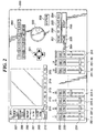
- FIG. 2 shows the appearance of a panel of the FIG. 1 apparatus.
- the display device 101, the fader 102 and the operating element group 103, all appearing in FIG. 1, are arranged on the panel.
- Reference numeral 201 designates a display 201 corresponding to the display device 101 in FIG. 1.
- Reference numeral 210 designates a shift key
- reference numerals 211 to 215 designate function keys F1 to F5.
- Reference numeral 221 designates a cursor-moving key for use in moving a cursor displayed on the display 201, and reference numeral 223 an enter key.
- reference numeral 222 designates a value-entering operating element (data input dial) for use in changing values set for various data.
- Reference numerals 231-1 to 231-16 designate respective operating element sets to be assigned to predetermined mixer input channels, described hereinafter, for controlling the assigned mixer input channels.
- Each mixer input channel represents a channnel for a series of data to be input to mixing buses that perform mixing.
- the apparatus has twenty-four mixer input channels 1 to 24, which will be described in detail hereinafter with reference to FIG. 3.
- reference numeral 232 designates a SEL key for use in displaying a screen view associated with the corresponding mixer input channel to provide instructions for various settings (adjustment of frequency characteristics, control of a compressor and a pan, etc.).
- reference numeral 233 designates an ON key for switching on/off the mixer input channel
- reference numeral 234 a fader (slide volume-type operating element) for adjusting the volume level.
- the SEL key 232 and the ON key 233 are switches of a light emitting type which are lit when depressed into a selected state and extinguished when depressed again into a non-selected state.
- the operating element set 231-1 is assigned to the mixer input channel 1 and operates as an operating element set for controlling the mixer input channel 1.
- the operating element set 231-1 is assigned to the mixer input channel 17 and operates as an operating element set for controlling the mixer input channel 17.
- numeric characters "1" and "17" are printed above the operating element set 231-1.
- operating element sets 231-2 to 231-16 On the right side of the operating element set 231-1, there are arranged operating element sets 231-2 to 231-16 each formed similarly to the operating element set 231-1. Printed above each of the operating element sets 231-2 to 231-16 are numeric characters that each indicate a mixer input channel to be controlled thereby when the 1-16 ch (channel) selection key 261 or the 17-24 ch (channel) selection key 262 is depressed or turned on. In this connection, the operating element sets 231-15 and 231-16 have characters "RTN1" and "RTN2", respectively, printed above them at locations below respective numeric characters "15" and "16".
- the operating element sets 231-15 and 231-16 are each assigned to a 2-channel effect return channel (designated by reference numeral 313 in FIG. 3, referred to hereinafter) as an operating element set for controlling the same.
- reference numeral 241 designates an operating element set for controlling the whole 2-channel stereo output.
- Reference numeral 264 designates a SOLO key.
- SOLO key 264 When the SOLO key 264 is turned on (whereby the key top is lit), if one of the ON keys 233 for the respective selected channels is turned on, a sound is outputted only from a corresponding one of the channels.
- a REW key 251, an FF key 252, a play key 253, a REC key 254, a PAUSE key 255, and a STOP key 256 are for giving respective instructions for rewind, fast-forward, reproduction, recording, pause, and stop.
- Reference numeral 263 designates a group of recording track switches for selecting respective tracks to be recorded. When one of the switches with the numeric characters "1" to "16" printed thereon, respectively, is turned on, a track having the corresponding track number enters a recording enabled state.
- Reference numeral 265 designates a SETUP key. By turning on the SETUP key 265, it is possible to set patching between input and output, which will be described hereinafter.
- Reference numeral 266 designates a RECORDER key.
- Reference numeral 267 designates a QUICK REC key.
- a QUICK REC screen view is displayed, which facilitates execution of a plurality of assignments.
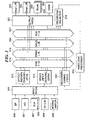
- FIG. 3 shows the outline of mixing processing implemented by the DSP 111.
- Reference numerals 301 to 306 designate inputs for mixing processing.
- An AD 301 represents inputs of eight channels digitized from respective eight analog inputs (AD 112 in FIG. 1).
- Slin's 302, 303 represent inputs inputted via input option cards inserted in the two slots (SL 114, SL 115 in FIG. 1), respectively.
- a card capable of receiving maximum eight channels of inputs can be used, which means that inputs of maximum 16 channels can be received via the two slots.
- a Din L/R 304 represents 2-channel stereo digital inputs (Din L/R 113 in FIG. 1).
- An internal sampler 305 represents inputs of eight channels of an internal waveform memory sound source, not shown.
- Each channel of the internal waveform memory sound source is capable of storing a desired musical tone waveform and generating a musical tone having the waveform, as required, when a predetermined switch therefor is depressed. For example, it is possible to store an effect sound, such as clapping of hands, in a channel thereof and generate the sound when necessary.
- An EF 306 represents two series of 2-channel stereo inputs from an external effector (effect-imparting device), not shown.
- the present apparatus is capable of inputting digital audio data taken from 1st to 6th channels of AUX buses, described hereinafter, to the external effector to impart effects thereto, and then returning the digital audio data imparted with the effects to inputs of the mixing processor.
- the EF 306 represents the effect inputs thus made.
- the DSP 111 also functions as an internal effector, not shown in FIG. 3, so that it is also possible to input digital audio data taken from 7th and 8th channels of the AUX buses, described hereinafter, to the external effector to impart effects thereto, and then return the resultant data to the mixing processor via the EF 306.
- Reference numerals 331 to 335 designate outputs subjected to the mixing processing.
- An Aout L/R 331 represents 2-channel stereo analog outputs (corresponding to the Aout L/R 118 in FIG. 1), while an Dout L/R 332 represents 2-channel stereo digital outputs (corresponding to the Dout L/R 119 in FIG. 1).
- Slout's 333, 334 represent respective outputs from option cards for data output inserted in the respective two slots. In the present apparatus, it is possible to insert a card capable of delivering maximum eight channels of outputs into each slot, and therefore outputs of maximum 16 channels can be delivered via the two slots.
- An OMNI 335 represents digital outputs of four channels (corresponding to the OMNI 120 in FIG. 1).
- Reference numerals 314 to 317 designate mixing buses for performing mixing processing.
- Reference numeral 314 designates 8-channel general-purpose buses (for use in recording and reproduction) which are denoted as BUS1 to BUS8.
- Reference numeral 315 designates 2-channel stereo recording/reproduction buses which are denoted as Stereo_L/R.
- Reference numeral 316 designates 2-channel stereo solo buses (for use in reproduction) which are denoted as Solo_L/R.
- reference numeral 317 designates AUX buses (for use in reproduction) which are denoted as AUX1 to AUX8.
- Reference numeral 312 designates mixer input channels.
- the mixer input channels represent channels for series of data to be input to the mixing buses 314 to 317 that carry out mixing processing.
- the mixer input channels 312 include 24 channels in total.
- each mixer input channel can be selectively connected to a desired one of the mixing buses.
- a signal subjected to AUX level control after channel level control from each mixer input channel to the eight AUX buses AUX1 to AUX8.
- First 16 channels of the 24 channels of the mixer input channels 312 have respective direct-out connections for directly outputting signals to 16 tracks of an internal recorder, respectively.
- a signal is inputted from an n-th input channel to an n-th track, which means that n input channels are in one-to-one correspondence with the n tracks.
- signals can be delivered from the mixer input channels to the output terminals 331 to 335 via an output patch 321, described hereinafter.
- the effect return channels 313 receive signals returned from the 2-channel external effector or the 2-channel internal effector.
- the operating element sets 231-15, 231-16, described with reference to FIG. 2 to the respective effect return channels 313, it is possible to carry out adjustment of frequency characteristics, control of the compressor and the pan, etc. (by the SEL keys appearing in FIG. 2) and adjustment of a volume level (by the faders appearing in FIG. 2).
- the effect return channels can be connected to desired ones of the mixing buses.
- Any one of the 38 inputs in total of the external inputs (301 to 304, 306) of maximum 30 channels and the internal inputs (305) of 8 channels can be selectively assigned to the mixer input channels 312 and the effect return channels 313.
- An input patch 311 carries out the assignment. A screen view displayed for use in carrying out the assignment by the input patch 311 will be described hereinafter with reference to FIG. 4.
- An HD recorder 319 is an internal recorder capable of 16-track recording/16-track reproduction. Data can be selectively inputted to each track as a recording input from any one of 26 channels in total of the eight channnels of the general-purpose buses BUS1 to BUS8, the 16 channels of direct-out connections from the mixer input channels 312, and the two channels of the stereo recording/reproduction buses Stereo_L/R. The assignment is carried out by a recording selector 318. A screen view displayed for use in carrying out the assignment by the recording selector 318 will be described hereinafter with reference to FIG. 4.
- a reproduced output from each track of the HD recorder 319 is supplied to a corresponding one of the recorder channels 320 arranged in a manner corresponding to the 16 tracks of the internal recorder.
- each recorder channel 320 can carry out adjustment of frequency characteristics, control of the compressor and the pan, etc. (by the SEL key appearing in FIG. 2), and adjustment of a volume level (by the fader appearing in FIG. 2) concerning a signal to be inputted.
- Each recorder channel is supplied with a recording input for recording a corresponding track (when data reproduced from the HD recorder 319 is returned to one of the recording buses for recording) or a reproducing output for reproduction of a corresponding track.
- a signal subjected to channel level control by the fader from each recorder channel 320 to one of the eight general-purpose buses BUS1 to BUS8 and the two stereo recording buses Stereo_L/R. It is also possible to selectively output a signal before being subjected to channel level control, from each recorder channel 320 to one of the two solo buses Solo_L/R. Further, it is possible to selectively output a signal subjected to AUX level control after channel level control, from each recorder channel to one of the eight AUX buses AUX1 to AUX8.
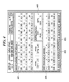
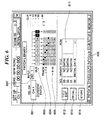
- FIG. 4 shows an example of the screen view via which the assignment by the input patch 311 or the recording selector 318 is carried out.
- the screen view is displayed by turning on the SETUP key 265 in FIG. 2.
- MIXER CHANNEL INPUT ASSIGN designated by reference numeral 401 denotes an area from which instructions are given as to which of the inputs 301 to 306 should be assigned to each of the mixer input channels 1 to 24 and the effect return channels 313.
- Numeric characters "1" to "24” displayed in this order represent the mixer input channels 1 to 24, respectively.
- Inputs assigned to the respective mixer input channels are indicated as “AD1", “AD2”, ... "SL1-1", “SL1-2”, ... “SL2-1”, “SL2-2”, ... , which are displayed under the respective numeric characters "1” to "24".
- "AD1", “AD2”, ... represent a first channel, a second channel, ... of the analog inputs AD 301.
- EEFFECT PATCH designated by reference numeral 402 denotes an area for displaying inputs assigned to the respective internal effectors.
- EEFF1" and “EFF2” represent the internal effectors.
- “EFF1” and “EFF2” are assigned to the AUX buses AUX7 and AUX8, respectively, such that data is inputted into the effectors via the AUX buses AUX7 and AUX8.
- HDR TRACK INPUT ASSIGN designated by reference numeral 403 denotes an area for displaying inputs assigned by the recording selector 318.
- Numeric characters “1” to “16” displayed in this order represent the 16 tracks, respectively.
- Inputs assigned to the respective tracks are indicated as “BUS1", “BUS2”, ... "DIR1”, “DIR2”, ..., which are displayed under the respective numeric characters "1” to "16”.
- BUS1", “BUS2”, ... represent the inputs from the general-purpose buses BUS1 to BUS8, while “DIR1”, “DIR2”, ... represent the inputs from the direct-out connections of the respective mixer input channels 312.
- the FIG. 4 screen view enables setting of input sources for the mixer input channels 312, the internal effectors and the tracks of the HD recorder 319.
- the cursor is moved by using the cursor-moving key 221 to an area displaying the desired input channel, and then by operating the value-entering operating element (data input dial) 222, input sources available for the input channel are sequentially displayed so as to allow the user to select a desired input source.
- the external inputs from the slots are each selectable as an input source only when at least one input card is inserted in any of the slots.
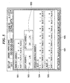
- FIG. 5 shows an example of the screen view from which the assignment by the output patch 321 is carried out.
- the screen view is displayed by specifying a page designated by reference numeral 404 in FIG. 4.
- OMNI OUT ASSIGN designated by reference numeral 501 denotes an area displaying a status of assignment effected for the omni output OMNI335.
- the buses AUX1 to AUX4 of the AUX buses 317 are assigned to four digital output terminals of the omni output OMNI335, respectively, as input sources for the same.
- "DOUT ASSIGN” designated by reference numeral 502 denotes an area displaying a status of assignment effected for the 2-channel stereo digital outputs Dout L/R 332.
- the 2-channel stereo recording/reproduction buses Stereo_L/R 315 are assigned to the stereo digital outputs Dout L/R 332 as input sources for the same.
- ST OUT ASSIGN designated by reference numeral 503 denotes an area displaying a status of assignment effected for the 2-channel stereo analog outputs AoutL/R 331.
- the 2-channel stereo recording/reproduction buses Stereo_L/R 315 are assigned to the stereo analog outputs Aout L/R 331 as input sources for the same.
- "SLOT1" designated by reference numeral 504 and “SLOT2" designated by reference numeral 505 denote areas displaying respective statues of assignment effected for the option cards (output cards) inserted in the slots 1 and 2, respectively.
- the general-purpose buses BUS1 to BUS8 are assigned to each of the option cards as input sources for the same.
- the FIG. 5 screen view enables setting of input sources for the output terminals. For example, in setting an input source for an output terminal, the cursor is moved by using the cursor-moving key 221 to an area displaying the desired output terminal, and then by operating the value-entering operating element (data input dial) 222, input sources available for the output terminal are sequentially displayed so as to allow the user to select a desired input source. It goes without saying that setting of input sources for an output card is possible only when at least one output card is inserted in any of the slots.
- FIG. 6 shows a display screen view which enables the user to grasp a patching status for recording (status of assignment of each channel) at a glance.
- This screen view is displayed by specifying a page designated by reference numeral 405 in FIG. 4 or 5.
- "SEL CH” designated by reference numeral 601 denotes an area indicating which channel is currently displayed. In the illustrated example, "CH1" is displayed, so that the user can understand that the present screen concerns the mixer input channel 1.
- the user can select one of the 24 mixer input channels 312 and the 2 effect return channels 313.
- the user can also select a desired channel by depressing the SEL key of any of the operating element sets 231-1 to 231-16 and 241 in FIG. 2.
- "INPUT” designated by reference numeral 602 denotes an area displaying an input source for the channel.
- AD1 is displayed, and hence the user can understand that the present input source for the mixer input channel 1 is the analog input AD1.
- "BUS” designated by reference numeral 603 denotes an area displaying an output destination of data from the channel.
- boxed numeric characters "1" to "8” indicate respective statuses of output from the channel to the buses BUS1 to BUS8 of the general-purpose buses 314.
- a boxed symbol “ST” indicates a status of output from the channel to the stereo recording buses Stereo_L/R 315, while a boxed symbol “D” indicates a status of output by a direct-out connection from the channel.
- FIG. 6 example shows that data is outputted from the mixer input channel 1 to the stereo recording buses Stereo_L/R 315 and the direct-out connection.
- the direct-out connection to the internal recorder is always in the ON or selected state, because the recorder can determine whether or not to accept direct output from the mixer input channel.
- the solo buses Solo_L/R 316 and the AUX buses 317 are not displayed as output destinations since they are not recording buses.
- TRACK1-8 designated by reference numeral 604 and "TRACK9-16" designated by reference numeral 605 denote a state of connection for a recording output, between each bus and each track of the recorder. Small rectangles represent the respective tracks. Tracks displayed in reverse video indicate that they are set to receive outputs from respective corresponding buses.
- the FIG. 6 screen view enables the user to comprehend at a glance from which source data is received, through which bus the data is sent, and on which track the data is recorded. Further, the user can change settings in the areas "INPUT” and "BUS", via this screen view. However, data of settings for the recording output destinations TRACK cannot be changed via the present screen view.
- Reference numeral 611 designates a list of names of files storing the respective patching statuses described above.
- a STORE button 614 allows the present settings to be stored in a file with a file name assigned thereto.
- a RECALL button 613 allows the patching status stored in the file to be loaded (read and reproduced).
- a TITLE EDIT button 612 allows the file name of the file to be changed.
- FIG. 7 shows a screen view showing to which of the general-purpose buses BUS1 to BUS8 each of the input channels (mixer input channels) is set for outputting data.
- a page 701 is an image displayed in association with the input channels 1 to 16, while a page 702 is an image displayed in association with the input channels 17 to 24.
- Reference numeral 711 designates a display area concerning the input channel 1, which shows a status of assignment of output from the input channel 1 to the general-purpose buses BUS1 to BUS8 and the stereo recording buses Stereo_L/R. Boxed numeric characters "1" to "8” represent the respective general-purpose buses BUS1 to BUS8, and a boxed symbol "ST" the stereo recording buses Stereo_L/R. When any one of them is displayed in reverse video, it indicates that the output from the input channel 1 is assigned to the bus.
- Reference numeral 712 designates settings for a pan (left-right localization) of the input channel 1. The above settings can be changed via the present screen view.
- mixer input channels inputs from another device or the like and inputs of signals generated by the recorder (i.e. recorder channels) are discriminated from each other.
- the mixer input channels are differentiated from the recorder channels in the following points (1) and (2):
- the present apparatus carries out processing in a 16-bit mode or in a 24-bit mode.
- the bit number of data to be recorded is 16
- the bit number of data to be recorded is 24.
- the bit number of sound data of a song once generated can never be changed afterwards.
- the number of tracks available for simultaneous recording and reproduction depends on whether the bit number of sound data to be recorded is 16 or 24. So long as the bit number is the same, as the number of tracks for simultaneous recording is increased, the number of tracks available for simultaneous reproduction is reduced. In the following, details of the manner of simultaneous recording and reproduction performed by the present apparatus will be described.
- the number of tracks for simultaneous recording when the number of tracks for simultaneous recording is 0 to 8, all the 16 tracks can be reproduced simultaneously. When the number of track for simultaneous recording is 9 to 16, 8 tracks can be then reproduced simultaneously. The 8 tracks for reproduction may be the same tracks as those for recording. Further, if recording is performed on stereo tracks (mixing-down mode), 16 tracks other than the stereo tracks cannot be set for recording, so that all the 16 tracks are used exclusively for reproduction. In other words, all the 16 tracks can be reproduced simultaneously.
- the number of tracks for simultaneous recording when the number of tracks for simultaneous recording is 0 to 2, all the 16 tracks can be then reproduced simultaneously.
- the number of tracks for simultaneous recording is 3 to 4, 12 tracks can be then reproduced simultaneously.
- the number of track for simultaneous recording is 5 to 8, 8 tracks can be then reproduced simultaneously.
- the number of track for simultaneous recording is 9 to 16, no tracks can be then reproduced simultaneously.
- recording is performed on stereo tracks (mixing-down mode)
- 16 tracks other than the stereo tracks cannot be set for recording, so that all the 16 tracks can be used exclusively for reproduction. In short, all the 16 tracks can be reproduced simultaneously.
- FIG. 8 shows a track view screen displayed by a predetermined key operation.
- the track view screen displays recording states of a plurality of tracks of the internal recorder.
- the symbol “T” represents a track number.
- the track numbers are fixedly set.
- the symbol “B” represents an input source from which data is inputted to the corresponding track.
- B1 represents an input from the general-purpose bus BUS1 (similarly, “Bx” corresponds to an input from “BUSx”), and “D9” a direct input from the input channel 9 (similarly, “Dx” corresponds to a direct input from the input channel x).
- NAME represents a name arbitrarily assigned to the corresponding track.
- the symbol “V” represents a virtual track number. In the present apparatus, each track has eight virtual tracks, and one of the virtual tracks is selected for use.
- the symbol “M” represents an ON/OFF state indicative of whether muting of sound data reproduced from each track is carried out.
- a normally-displayed rectangle indicates a mute-off state, while a rectangle displayed in reverse video indicates a mute-on state.
- the symbol "I" represents an ON/OFF state of recording of each track.
- a normally-displayed rectangle indicates the OFF state of recording, while a rectangle displayed in reverse video indicates the ON state of recording.
- the ON/OFF state of recording of each track can be designated by the recording track switches 263 in FIG. 2.
- each track is illustrated in the form of a bar graph.
- the abscissa represents a time axis.
- Each bar in the graph indicates existence of data recorded over a time range corresponding to the length of the bar.
- Input for each track is selected between recording input from an input channel corresponding to the track and reproduction output from the same.
- "INPUT MONITOR” designated by reference numeral 803 shows a setting for the selection.
- "AUTO” is a button for use in carrying out setting for a punch-in. Reproduction output is continuously selected up to a (punch) in-point set by the "AUTO” button, recording input is continuously selected from the in-point to an out-point, and from the out-point, reproduction input is continuously selected.
- INDI is a button for use in carrying out individual setting on a track-by-track basis. For a track specified as a recording track, recording input is selected. However, by changing the setting, it is possible to select recording input even for a reproducing track.
- "ALL" is a button for use in selecting recording input for all the tracks.
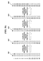
- FIGS. 9A and 9B show how reproducing tracks are automatically muted in response to designation of recording tracks.
- Each track can be designated as a recording track by turning on a corresponding one of the 16 recording track switches 263 (see FIG. 2) corresponding to the 16 tracks.
- a plurality of recording track switches can be turned on simultaneously. Therefore, when a plurality of tracks are designated as recording tracks, sounds based on recording input signals are recorded simultaneously on the respective tracks designated as recording tracks, in response to an instruction for starting the recording.
- FIG. 9A shows changes in the settings when recording tracks are increased by twos in the 24-bit mode.
- tracks are automatically muted (in descending order of the track number, i.e. the largest track number first) by a number corresponding to that of tracks inhibited from use for reproduction. More specifically, when the recording track switches 2 and 3 are turned on in a state 901 appearing on the left-hand side of FIG. 9A, where the track 1 is already in a recording state, the tracks 2 and 3 in addition to the track 1 are placed in a recording state, as shown by the following state 902 in the figure. At this time, since the number of recording tracks is thus increased to 3, the number of tracks available for reproduction is reduced to 12. Consequently, the tracks 13 to 16 having the largest track numbers are automatically muted, and the remaining twelve tracks 1 to 12 are used for reproduction.
- the tracks 4 and 5 in addition to the tracks 1 to 3 are placed in a recording state, as shown by the following state 903 in the figure.
- the number of recording tracks is thus increased to 5
- the number of tracks available for reproduction is reduced to 8. Consequently, the tracks 9 to 12 having the largest track numbers among the tracks 1 to 12 are automatically muted in addition to the tracks 13 to 16 already muted, and the remaining twelve tracks 1 to 8 are used for reproduction.
- the tracks 1 to 7 are placed in a recording state, as shown by the following state 904 in the figure.
- the number of recording tracks is thus increased to 7, but the number of tracks available for reproduction does not change.
- the eight tracks 1 to 8 remain available for reproduction, and hence in the state 904, it is not required to increase the number of muted tracks.
- the tracks 1 to 9 are placed in a recording state, as shown by the following state 905 in the figure. At this time, since the number of recording tracks is thus increased to 9, the number of tracks available for reproduction is reduced to 0. Consequently, all the tracks are automatically muted.
- FIG. 9B shows a state where 8 recording tracks and 2 muted tracks are set in the 16-bit mode, as well as changes which occur when 9 tracks are designated as recording tracks in this state.
- 6 muted tracks are automatically set in addition to the two already set. More specifically, when the recording track switches 1, 2, 5, 6, 7, 8, 11, 13 are turned on in a state 911 appearing on the left-hand side of FIG. 9B, where the tracks 4 and 5 are muted, the tracks corresponding to the recording track switches turned on are placed in a recording state, as shown by the following state 912 in the figure. At this time, the number of recording tracks is thus increased to 8, but all the 16 tracks are still available for reproduction. Consequently, since it is not required to increase muted tracks, there occurs no change in the status of the muting of tracks.
- the recording track switch 12 when the recording track switch 12 is turned on in the state 912, the number of recording tracks is increased to 9 as shown by the following state 913, and hence the number of tracks available for reproduction is reduced to 8. Consequently, the tracks 11 to 16 having the largest track numbers are automatically muted in addition to the tracks 4 and 5 already muted, and the remaining eight tracks 1 to 3 and 6 to 10 are used for reproduction.
- Transition from the state 913 to a state 914 shows a case of changing a track to be muted.
- muting of one track is started, and instead, the muting of another track is canceled.
- the number of muted tracks is larger than that of tracks inhibited from use for reproduction, it is possible to change one or more tracks to be muted, as desired.
- FIG. 10 shows a view of a QUICK REC screen displayed in response to operation of the QUICK REC key 267 appearing in FIG. 2. While the present apparatus allows flexible assignment by the input patch and the output patch, it takes time and labor to set the patching. To eliminate this inconvenience, the FIG. 10 QUICK REC screen is provided so as to allow a plurality of input channels, routings and tracks to be collectively set in a manner suited for an initial recording.
- the input patch is set such that each input displayed in the "INPUT CH” is inputted to one of the input channels displayed in the "MIXER CH", and at the same time the recording selector 318 is set such an input from each input channel displayed in the "MIXER CH” is inputted (via the direct-out connection) to one of the tracks of the internal recorder displayed in the "REC TR".
- the objects of the present invention may be accomplished by supplying a storage medium in which is stored a software program realizing the functions of the above-mentioned embodiments to a system or apparatus, and causing a computer (CPU or MPU) of the system or apparatus to read out and execute the program stored in the storage medium.
- a computer CPU or MPU
- the code of the program itself read out from the storage medium achieves the novel functions of the above embodiments, and the storage medium storing the program constitutes the present invention.
- the storage medium for supplying the program to the system or apparatus may be in the form of a floppy disk, a hard disk, an optical memory disk, an magneto-optical disk, a CD-ROM, a CD-R (CD-Recordable), DVD-ROM, a semiconductor memory, a magnetic tape, a nonvolatile memory card, or a ROM, for instance.
- the program code may be supplied from a server computer via a MIDI apparatus or a communication network.
- a CPU or the like arranged in the function extension board or the function extension unit may carry out part or whole of actual processing in response to the instructions of the code of the next program, thereby making it possible to achieve the functions of the above embodiments.
Landscapes
- Engineering & Computer Science (AREA)
- Multimedia (AREA)
- Signal Processing (AREA)
- Management Or Editing Of Information On Record Carriers (AREA)
- Circuit For Audible Band Transducer (AREA)
- Studio Circuits (AREA)
- Signal Processing For Digital Recording And Reproducing (AREA)
- Signal Processing Not Specific To The Method Of Recording And Reproducing (AREA)
- Indexing, Searching, Synchronizing, And The Amount Of Synchronization Travel Of Record Carriers (AREA)
Abstract
Description
Claims (4)
- A multi-track digital recording/reproducing apparatus for recording and reproducing digital audio data by using multiple tracks, comprising:recording track-designating means for designating at least one track for recording, from a plurality of tracks, as desired;reproducible track number-determining means for determining a number of tracks that can be reproduced, in response to the designation of the at least one track for recording; andreproducing track number-limiting means for limiting a number of tracks for reproduction to the number of tracks that can be reproduced, by automatically muting at least predetermined one of tracks designated for reproduction, when the number of tracks designated for reproduction is larger than the number of tracks that can be reproduced.
- A multi-track digital recording/reproducing apparatus according to claim 1, including reproducing track-changing means capable of changing any of the tracks designated for reproduction, so long as the number of tracks designated for reproduction is equal to or smaller than the number of tracks that can be reproduced.
- A multi-track digital recording/reproducing method using a multi-track digital recording/reproducing apparatus for recording and reproducing digital audio data by using multiple tracks,
the multi-track digital recording/reproducing method comprising the steps of:designating at least one track for recording, from a plurality of tracks, as desired;determining a number of tracks that can be reproduced, in response to the designation of the at least one track for recording; andlimiting a number of tracks for reproduction to the number of tracks that can be reproduced, by automatically muting at least predetermined one of tracks designated for reproduction, when the number of tracks designated for reproduction is larger than the number of tracks that can be reproduced. - A recording/reproducing program executed by a computer, the program using a multi-track digital recording/reproducing apparatus for recording and reproducing digital audio data by using multiple tracks,
the program comprising:a recording track-designating module that designates at least one track for recording, from a plurality of tracks, as desired;a reproducible track number-determining module that determines a number of tracks that can be reproduced, in response to the designation of the at least one track for recording; anda reproducing track number-limiting module that limits a number of tracks for reproduction to the number of tracks that can be reproduced, by automatically muting at least predetermined one of tracks designated for reproduction, when the number of tracks designated for reproduction is larger than the number of tracks that can be reproduced.
Applications Claiming Priority (2)
| Application Number | Priority Date | Filing Date | Title |
|---|---|---|---|
| JP2000232526A JP3480433B2 (en) | 2000-07-31 | 2000-07-31 | Multitrack digital recording / playback device |
| JP2000232526 | 2000-07-31 |
Publications (2)
| Publication Number | Publication Date |
|---|---|
| EP1178485A2 true EP1178485A2 (en) | 2002-02-06 |
| EP1178485A3 EP1178485A3 (en) | 2005-01-26 |
Family
ID=18725200
Family Applications (1)
| Application Number | Title | Priority Date | Filing Date |
|---|---|---|---|
| EP01117880A Withdrawn EP1178485A3 (en) | 2000-07-31 | 2001-07-23 | Multi-track digital recording/reproducing apparatus and method and multi-track digital recording/reproducing program |
Country Status (2)
| Country | Link |
|---|---|
| EP (1) | EP1178485A3 (en) |
| JP (1) | JP3480433B2 (en) |
Cited By (1)
| Publication number | Priority date | Publication date | Assignee | Title |
|---|---|---|---|---|
| US11227615B2 (en) | 2017-09-08 | 2022-01-18 | Sony Corporation | Sound processing apparatus and sound processing method |
Families Citing this family (1)
| Publication number | Priority date | Publication date | Assignee | Title |
|---|---|---|---|---|
| JP6056437B2 (en) | 2011-12-09 | 2017-01-11 | ヤマハ株式会社 | Sound data processing apparatus and program |
Family Cites Families (3)
| Publication number | Priority date | Publication date | Assignee | Title |
|---|---|---|---|---|
| JPS58105414A (en) * | 1981-12-16 | 1983-06-23 | Matsushita Electric Ind Co Ltd | Multi-channel digital recording and reproducing device |
| JPH04232666A (en) * | 1990-12-28 | 1992-08-20 | Casio Comput Co Ltd | Digital recorder |
| JP2000163867A (en) | 1997-12-22 | 2000-06-16 | Sony Corp | Data processing device |
-
2000
- 2000-07-31 JP JP2000232526A patent/JP3480433B2/en not_active Expired - Fee Related
-
2001
- 2001-07-23 EP EP01117880A patent/EP1178485A3/en not_active Withdrawn
Cited By (1)
| Publication number | Priority date | Publication date | Assignee | Title |
|---|---|---|---|---|
| US11227615B2 (en) | 2017-09-08 | 2022-01-18 | Sony Corporation | Sound processing apparatus and sound processing method |
Also Published As
| Publication number | Publication date |
|---|---|
| JP3480433B2 (en) | 2003-12-22 |
| EP1178485A3 (en) | 2005-01-26 |
| JP2002050124A (en) | 2002-02-15 |
Similar Documents
| Publication | Publication Date | Title |
|---|---|---|
| US7392101B2 (en) | Multi-track digital recording/reproducing apparatus and method, multi-track digital recording/reproducing program | |
| JP3700931B2 (en) | Multitrack digital recording and playback device | |
| US5225618A (en) | Method and apparatus for studying music | |
| US9619431B2 (en) | Music and audio playback system | |
| US7119267B2 (en) | Portable mixing recorder and method and program for controlling the same | |
| JP3659190B2 (en) | Playback control apparatus, method and program | |
| JP3478253B2 (en) | Multitrack digital recording / playback device | |
| JP3823705B2 (en) | Audio data mixing device including pad, control method thereof, and storage medium | |
| US20020015504A1 (en) | Mixing apparatus with recording/reproducing function | |
| US7308324B2 (en) | Data signal processing apparatus | |
| GB2343049A (en) | Digital audio or video playback arrangement and method of operation thereof | |
| JPH01501663A (en) | Control device | |
| JP3565150B2 (en) | Multitrack digital recording / playback device | |
| JP3480433B2 (en) | Multitrack digital recording / playback device | |
| JP3478254B2 (en) | Multitrack digital recording / playback device | |
| JP3982287B2 (en) | Digital recorder with mixer | |
| JP2004265579A (en) | Multi-track digital sound recording and reproducing device | |
| Smarties | Roland DM80 (SOS Jul 1992) | |
| Rothstein | Audio Matrix 16 Patch Bay by 360 Systems | |
| Center | Operator’s Manual | |
| JPH07141842A (en) | Audio editing equipment | |
| JPH0764581A (en) | Audio / video playback system | |
| JP2001043604A (en) | Recording and playback device | |
| JPH02166819A (en) | Digital signal processing method and circuit | |
| JPH08110784A (en) | Karaoke rendition player |
Legal Events
| Date | Code | Title | Description |
|---|---|---|---|
| PUAI | Public reference made under article 153(3) epc to a published international application that has entered the european phase |
Free format text: ORIGINAL CODE: 0009012 |
|
| 17P | Request for examination filed |
Effective date: 20010723 |
|
| AK | Designated contracting states |
Kind code of ref document: A2 Designated state(s): AT BE CH CY DE DK ES FI FR GB GR IE IT LI LU MC NL PT SE TR |
|
| AX | Request for extension of the european patent |
Free format text: AL;LT;LV;MK;RO;SI |
|
| PUAL | Search report despatched |
Free format text: ORIGINAL CODE: 0009013 |
|
| AK | Designated contracting states |
Kind code of ref document: A3 Designated state(s): AT BE CH CY DE DK ES FI FR GB GR IE IT LI LU MC NL PT SE TR |
|
| AX | Request for extension of the european patent |
Extension state: AL LT LV MK RO SI |
|
| AKX | Designation fees paid |
Designated state(s): DE GB IT |
|
| 17Q | First examination report despatched |
Effective date: 20061019 |
|
| RAP1 | Party data changed (applicant data changed or rights of an application transferred) |
Owner name: YAMAHA CORPORATION |
|
| STAA | Information on the status of an ep patent application or granted ep patent |
Free format text: STATUS: THE APPLICATION IS DEEMED TO BE WITHDRAWN |
|
| 18D | Application deemed to be withdrawn |
Effective date: 20140201 |