EP1178428A1 - Dot code and two-dimensional code - Google Patents
Dot code and two-dimensional code Download PDFInfo
- Publication number
- EP1178428A1 EP1178428A1 EP00913037A EP00913037A EP1178428A1 EP 1178428 A1 EP1178428 A1 EP 1178428A1 EP 00913037 A EP00913037 A EP 00913037A EP 00913037 A EP00913037 A EP 00913037A EP 1178428 A1 EP1178428 A1 EP 1178428A1
- Authority
- EP
- European Patent Office
- Prior art keywords
- code
- dots
- dot
- color
- column
- Prior art date
- Legal status (The legal status is an assumption and is not a legal conclusion. Google has not performed a legal analysis and makes no representation as to the accuracy of the status listed.)
- Ceased
Links
Images








Classifications
-
- G—PHYSICS
- G06—COMPUTING OR CALCULATING; COUNTING
- G06K—GRAPHICAL DATA READING; PRESENTATION OF DATA; RECORD CARRIERS; HANDLING RECORD CARRIERS
- G06K19/00—Record carriers for use with machines and with at least a part designed to carry digital markings
- G06K19/06—Record carriers for use with machines and with at least a part designed to carry digital markings characterised by the kind of the digital marking, e.g. shape, nature, code
- G06K19/06009—Record carriers for use with machines and with at least a part designed to carry digital markings characterised by the kind of the digital marking, e.g. shape, nature, code with optically detectable marking
- G06K19/06037—Record carriers for use with machines and with at least a part designed to carry digital markings characterised by the kind of the digital marking, e.g. shape, nature, code with optically detectable marking multi-dimensional coding
-
- G—PHYSICS
- G06—COMPUTING OR CALCULATING; COUNTING
- G06K—GRAPHICAL DATA READING; PRESENTATION OF DATA; RECORD CARRIERS; HANDLING RECORD CARRIERS
- G06K1/00—Methods or arrangements for marking the record carrier in digital fashion
- G06K1/12—Methods or arrangements for marking the record carrier in digital fashion otherwise than by punching
- G06K1/121—Methods or arrangements for marking the record carrier in digital fashion otherwise than by punching by printing code marks
Definitions
- the present invention relates to dot codes and two-dimensional codes.
- the invention relates to dot codes and two-dimensional codes printed to occupy a small area that can accurately be read.
- Fig. 1 shows one example of conventional two-dimensional codes. As shown in Fig. 1, this two-dimensional code is constituted of a collection of blocks each having a predetermined size. A predetermined code is represented by presence/absence of blocks at respective positions. The two-dimensional code can be printed on any printed matter or the like to allocate various types of information to the printed matter.
- the two-dimensional code has a problem that the printed code occupies a large area since the blocks mentioned above each consist of a plurality of pixels.
- dots could actually be printed at various positions as indicated by broken lines.
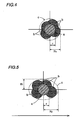
- Fig. 4 when one pixel (dot) is originally intended to be printed at a predetermined position a (indicated by a white circle), dots could actually be printed at various positions b (indicated by hatching).
- perimeter C indicated by dotted line
- radius R1 is larger than radius r, extended from the originally intended center, where the perimeter of the dot should be located.
- radius R1 in the main scanning direction (downward direction in Fig. 5) equal to that shown in Fig. 4 while radius R2 in the sub scanning direction (rightward direction in Fig. 5) is greater than radius R1.
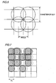
- each dot of the printer has its diameter set equal to or somewhat greater than pitch P0 corresponding to the highest resolution of the printer.
- pitch P0 corresponding to the highest resolution of the printer.
- Fig. 7 when no dot is printed in a central region and dots are printed in respective regions horizontally and vertically adjacent to the central region, the printed dots protrude from respective adjacent regions. Accordingly, when a resultant two-dimensional code is read, the code could be read erroneously such that a dot is present in the central region. This is more clearly seen when the deviation of dots as described with reference to Fig. 4 or 5 is considered.
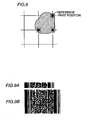
- Fig. 8 shows one example of the case as discussed above. Specifically, according to the example in Fig. 8, pixels represented by black circles in Fig. 8 are printed respectively at reference print positions represented by squares in Fig 8. Actually, however, printed three pixels are deviated from respective reference positions and thus seem to be one pixel.
- a two-dimensional code usually has an error correction code added thereto.
- the additional error correction code makes the print area larger as shown in Fig. 9B than that where no error correction code is added as shown in Fig. 9A.
- Pattern codes as described above are generally printed in monochrome. A problem here is that only one type of information can be allocated to a pattern code.
- a color code as shown in Fig. 10 for example is accordingly proposed that is represented by a pattern with a plurality of color elements such as cyan (C), white (W), black (BL) or magenta (M).
- this color code has black (BL), magenta (M), cyan (C) or white (W) to which code "00", "01", "10” or "11” is allocated. Only one code "101100100101” is thus allocated to the pattern "C", “W”, “BL”, “C”, “M”, “M” for example shown in Fig. 10.
- a problem of this conventional pattern code is that a secret code cannot be embedded in an original code for example.
- One object of the invention is to provide a code printed to occupy a small area that can correctly be read.
- Another object of the invention is to provide a code that can represent information of multiple types.
- Still another object of the invention is to provide a printing apparatus capable of supplying a pattern code to which a plurality of codes are allocated.
- a further object of the invention is to provide a reading apparatus capable of reading a plurality of codes from one pattern code, the codes being allocated to the pattern code.
- a dot code according to the present invention includes dots arranged on the basis of a pitch approximately twice as large as a diameter of a dot.
- the dots are arranged with a pitch twice as large as the diameter of a dot. Then, the dot code can be provided that is printed to occupy a relatively small area and can be read accurately.
- a dot code includes dots arranged with a minimum pitch in a region on a reference line and arranged with a pitch longer than the minimum pitch in a remaining region except for the region on the reference line.
- the dot code thus includes dots arranged with the minimum pitch in the region on the reference line and arranged with the pitch longer than the minimum pitch in a residual region except for the region on the reference line. Then, the dots arranged in the remaining region except for the region on the reference line can correctly be read.
- a dot code includes dots arranged at respective positions in a region on a reference line and arranged at respective positions corresponding to data in a remaining region except for the region on said reference line, and a region where none of said dots is arranged is formed between the reference line and the remaining region.
- the region without dot arranged therein is formed between the reference line and the remaining region. It is thus possible to accurately detect the reference line region and accurately read dots arranged in the remaining region.
- a dot code includes dots colored in colors corresponding to respective positions where the dots are arranged.
- the dots are colored in respective colors corresponding to the positions where the dots are arranged, erroneous reading of the dots can be prevented.
- a dot code includes a header section and a data section, and dots have a pitch in the header section set at a greater value than that of a pitch in the data section.
- the dot pitch for the header section is set at a value greater than that of the dot pitch for the data section, it is possible to prevent any important information included in the header section from being erroneously detected.
- a two-dimensional code has an error correction code for a header section with a higher correction capability than that of an error correction code for a data section.
- the error correction code for the header section has a higher correction capability than that of the error correction code for the data section, the total amount of the two-dimensional code can be reduced while any error in important information included in the header section can be corrected accurately.
- a dot code includes dots arranged in each column with a pitch approximately twice as large as a diameter of a dot, the dots are arranged in a first column and arranged in a second column adjacent to and apart from the first column by the pitch approximately twice as large as the diameter of a dot, the dots arranged in the second column each being displaced in the direction of the column by almost the diameter of a dot from a position of the dot arranged in the first column.
- the dots are arranged with the pitch approximately twice as large as the diameter of a dot in each column, the dots are arranged in a first column and in the adjacent second column apart from the first column by the pitch approximately twice as large as the dot diameter, and the dots arranged in the second column are each displaced in the direction of the column by almost the diameter of a dot from the position of the dot arranged in the first column. Accordingly, the dot code can be implemented that is printed to occupy a relatively small area and can accurately be read.
- a pattern code is constituted of a plurality of elements in predetermined colors, and the colors of the elements are determined to allow the pattern code read with light in a first color to provide a first code and allow the pattern code read with light in a second color to provide a second code.
- the elements of the pattern code has colors determined such that the first code is obtained when the pattern code is read with a first color and the second code is obtained when the pattern code is read with the second color. Then, one pattern code can be implemented to which a plurality of codes are allocated.
- a printing apparatus for printing a pattern code constituted of a plurality of elements in predetermined colors on a medium includes capture means for capturing a plurality of data, determination means for determining the predetermined colors by combining the plurality of data captured by the capture means, and print means for printing the pattern code of the elements in the colors determined by the determination means on the medium.
- the printing apparatus prints the pattern code with the elements in colors determined by combining a plurality of captured data. Then, the printing apparatus can be provided capable of supplying one pattern code to which a plurality of codes are allocated.
- a reading apparatus for reading a pattern code constituted of a plurality of elements in predetermined colors from a medium on which the pattern code is printed includes generation means for generating light in a plurality of colors, control means for controlling the generation means to generate light in a predetermined color among the plurality of colors, and reading means for reading a first code from the pattern code on the medium when light in a first color is generated by the generation means and reading a second code from the pattern code on the medium when light in a second color is generated by the generation means.
- the reading apparatus reads the first code with light in the first color and reads the second code with light in the second color. Then, the reading apparatus can be provided capable of reading a plurality of codes from one pattern code to which the codes are allocated.
- a printing apparatus includes a data processing unit 1 and a printing unit 2.
- Data e.g. audio data
- Data processing unit 1 converts the input data into a pattern of the two-dimensional code and outputs the resultant pattern to printing unit 2.
- Printing unit 2 accordingly makes a print of (prints) the print pattern supplied from data processing unit 1 on card 3 formed of paper, plastic or the like.
- Fig. 13 shows an exemplary card 3 on which two-dimensional codes are printed in the above-described manner.
- four two-dimensional codes 21a-21d are printed on this card (these two-dimensional codes 21a-21d are simply referred to as two-dimensional code 21 if distinctions among these codes are unnecessary, this reference is herein applied to other discussions).
- Two-dimensional code 21a is divided into a header section 22a and a data section 23a. On header section 22a, type, version and further information concerning data recorded on data section 23a are recorded. Audio data in this example is recorded on data section 23a.
- two-dimensional codes 21b-21d have data recorded on header and data sections.
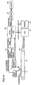
- Fig. 14 shows an example of a structure of a reading apparatus for reading card 3 on which two-dimensional code 21 is printed.
- Card 3 is placed on a belt 15 so that the upward-facing surface of card 3 has two-dimensional code 21 printed thereon.
- a motor 16 drives belt 15 to transport (move) card 3 from left to right as seen from Fig. 14.
- a light source 12 generates light according to a light source control signal supplied from an image data reading unit control circuit 13 to radiate card 3 with the generated light.
- a reading device 11 constituted of a CCD imaging unit for example is controlled by image data reading unit control circuit 13 to image the surface of card 3 on which two-dimensional code 21 is printed and thus output, to data processing unit 14, a resultant image signal obtained through the imaging.
- a synchronizing signal synchronized with an image reading operation is further supplied from image data reading unit control circuit 13. Synchronously with the synchronizing signal supplied from image data reading unit control circuit 13, data processing unit 14 binarizes and recognizes the image signal supplied from reading device 11 to generate a binary code in accordance with results of the recognition. Data processing unit 14 further converts the binary code into an analog audio signal to output the converted signal to a speaker 20 via an amplifier 19.
- a CPU 17 controls data processing unit 14 and motor 16. Data and program necessary for execution of various processes by CPU 17 are appropriately stored in a memory 18.
- CPU 17 also controls image data reading unit control circuit 13 to cause light source 12 to generate light to be emitted toward card 3.
- reading device 11 is controlled by image data reading unit control circuit 13 to read two-dimensional code 21 printed on card 3.
- Data processing unit 14 binarizes an image signal supplied from reading device 11, converts the binary signal into binary data and then converts the binary data into an analog audio signal.
- the analog audio signal is output to speaker 20 via amplifier 19.
- Printing unit 2 for printing of card 3 has the highest resolution corresponding to a pitch of value P0. Accordingly, pixels (dots) each have a diameter equal to or somewhat greater than value P0. Although dots are not perfect circles in terms of microscopic view, the dots are nearly circular.
- the diameter of a dot refers to the diameter of a corresponding circle of the dot.
- the dot diameter is herein defined to be equal to pitch value P0 corresponding to the highest resolution for convenience of description.
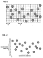
- Printing unit 2 prints a two-dimensional code on card 3 with print pitch P which is approximately twice as long as the dot diameter as shown in Fig. 15. Consequently, there are few dots adjacent to and overlapping each other even if printed dots are deviated from originally intended positions. Accordingly data can accurately be read.
- Fig. 16 shows scanning directions of reading device 11.
- card 3 is moved to the right relative to reading device 11 for reading of the two-dimensional code.
- the two-dimensional code is shown to be read by moving reading device 11 to the right (in sub scanning direction).
- the main scanning direction in Fig. 16 is accordingly the downward direction along reading device 11.
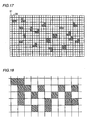
- Reading device 11 thus scans the code in the main and sub scanning directions and accordingly data processing unit 14 can obtain a resultant reading as shown in Fig. 17.
- a blackened cell indicates that a dot is detected while a white cell indicates that no dot is detected.
- the dimension of a cell in the vertical direction is defined by a pixel of the CCD imaging unit constituting reading device 11 and the dimension of the cell in the horizontal direction is defined by a speed per unit time in the sub scanning direction.
- data processing unit 14 determines, when two or more cells among 3 ⁇ 3 cells are blackened cells, that a dot is located at the 3 ⁇ 3 cells. This determination provides a result as shown in Fig. 18.
- One rectangle in Fig. 18 corresponds to a region formed of 3 ⁇ 3 cells in Fig. 15.
- a blackened region in Fig. 18 is a region where a dot is located as determined. In other words, the blackened regions in Fig. 18 correspond to black dots in Fig. 16.
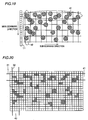
- a row of the two-dimensional code on at least one end thereof among rows in the sub scanning direction is defined as a reference row 41
- a column of the two-dimensional code on at least one end thereof among columns in the main scanning direction is defined as a reference column 42 (from which reading is started).
- dots are printed on all regions with a print pitch equal to pitch P0 of the highest resolution of printing unit 2.
- a resultant reading is the one as shown in Fig. 20.
- Dots must be printed with pitch P0 in reference row 41.
- the number of cells regarded as black cells in each row of cells (horizontally aligned cells) as a result of reading is counted to produce a histogram.
- the number of black cells in three rows belonging to reference row 41 is indicated by a histogram value that is considerably greater than the corresponding value regarding the number of black cells in rows of regions except for reference row 41. Accordingly, three rows of cells having black cells greater in number than a predetermined threshold can be detected as reference row 41.
- the number of black cells in each column of cells is counted to produce a histogram. Then, a histogram value for cells in three columns belonging to reference column 42 is greater than histogram values for cells in other columns. Accordingly, three columns having black cells greater in number than a predetermined threshold can be detected as columns of cells belonging to reference column 42.
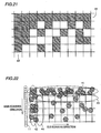
- Reference row 41 and reference column 42 are thus detected and thereafter grids 31 or grids 32 are arranged at every three rows or columns. Then, grids 31 and 32 corresponding to read pixels can be arranged.
- grids 31 and 32 are thus arranged and on the basis of which presence/absence of dots is determined to represent presence and absence of dots as black and white regions respectively.
- Regions corresponding to reference row 41 and reference column 42 are all black regions.
- Fig. 22 shows a structure of the two-dimensional code (dot code) having more accurately arranged grids 31 and 32 as an example.
- a reference row 43 is arranged inside a reference row 41 and a reference column 44 is arranged inside a reference column 42.
- No dot is arranged in reference row 43 and reference column 44.
- reference row 43 and reference column 44 are blank row and column respectively.
- Fig. 23 shows a resultant reading of the dot code shown in Fig. 22 by reading device 11. As shown in Fig. 23, each region of 3 ⁇ 3 cells in reference row 43 inside reference row 41 and in reference column 44 inside reference column 42 includes one or no black cell.
- the number of black cells in each column of cells shown in Fig. 23 is counted to represent the resultant numbers by means of a histogram as shown in Fig. 24.
- the number of black cells in a column of cells adjacent to reference column 42 is extremely smaller than that of black cells in the column of cells belonging to reference column 42. Then, the difference in number of black cells between columns adjacent to each other can be compared with a predetermined threshold to accurately detect reference column 42. In a similar manner, reference row 41 can more accurately be detected than that as shown by the example in Fig. 19.
- Fig. 25 shows a result of recognition by detecting reference rows 41 and 42 and reference columns 42 and 44 and arranging grids 31 and 32 to recognize presence/absence of dots.
- Fig. 26 shows another example of the two-dimensional code.
- This example has dots each printed in a color determined in advance depending on the position to allow the dots in different colors to alternately be arranged.
- This example also has a reference row 41 and a reference column 42.
- a dot D11 in a first color, a dot D12 in a second color, a dot D13 in the first color, a dot D14 in the second color, and a dot D 15 in the first color are alternately arranged in terms of color.
- the dot D11 in the first color, a dot D21 in the second color, a dot D31 in the first color, a dot D41 in the second color, and a dot D51 in the first color are alternately arranged in terms of color.
- dots in the first or second color are arranged as required according to data. The color of a dot is determined in advance depending on the position of the dot.
- the color of a dot is preliminarily determined according to the position of the dot, it is possible to decide the position of a printed dot from the color of the dot even if the printed dot is deviated from the originally intended position.
- Fig. 26 has dots of different colors printed in the pattern of a houndstooth check.
- the color of printed dots may be determined such that each column has its specific color as shown in Fig. 27 or each row has its specific color as shown in Fig. 28.
- Fig. 29 shows still another example of the two-dimensional code.
- dot pitch for a header section 22 and that for a data section 23 are set differently from each other.
- the dot pitch for header section 22 is set substantially greater than that for data section 23.
- a region of header section 22 corresponding to a 3 ⁇ 3-dot region of data section 23 has substantially one dot arranged therein. (3 ⁇ 3 dots in header section 22 are defined to be one dot.)
- the print pitch of header section 22 is six times as large as that of data section 23. Consequently, reading for header section 22 can more accurately be done than that for data section 23 to prevent the code from being erroneously detected.
- Data recorded on data section 23 is audio data for example. Even if the data on data section 23 is erroneously detected, the influence thereof is small. Dots are accordingly arranged in data section 23 at a relatively higher density.
- header section 22 It is desired that no error occurs for header section 22 since header section 22 usually has important information arranged therein. However, upon occurrence of any error, the error must be corrected. Then, as shown in Figs. 30A to 30C, it could be possible to add error correction codes to header section 22 and data section 23 to print the two-dimensional code.
- error correction codes having a high error correction capability are added to header section 22 and data section 23 respectively to ensure correction of any error for header section 22, the total code amount as shown in Fig. 30B is considerably greater than that of the two-dimensional code shown in Fig. 30A having no error correction code added thereto.
- Fig. 30C it would be possible to add an error correction code having a sufficient error correction capability to header section 22 and add an error correction code having a relatively lower error correction capability as compared with that for header section 22 to data section 23.
- the code amount of header section 22 is the same as that shown in Fig. 30B while the code amount of data section 23 can be made smaller than that shown in Fig. 30B. If data section 23 has audio data arranged therein, occurrence of any error exerts little influence. In such a case, the error correction code of data section 23 may have a relatively lower error correction capability than that of header section 22.
- the principle shown in Figs. 30A to 30C is applicable not only to dot code but also to barcode and other codes.
- a printing apparatus for printing data on a card and a reading apparatus for reading a card 3 on which a two-dimensional code is printed and a card 3 on which a two-dimensional code 21 is printed have the same structures as those of the first embodiment.
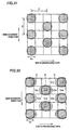
- a printing unit 2 of the second embodiment is the same as that of the first embodiment in that the two-dimensional code is printed on card 3 with print pitch P approximately twice as large as the dot diameter in both of the main and sub scanning directions as shown in Fig. 31.
- P0 pitch value
- the dot of cell C23 protrudes to a greater extent in the sub scanning direction (horizontal direction in Fig. 32) than that in the main scanning direction (vertical direction in Fig. 32).
- two cells C23 and C25 are adjacent to cell 24 in the sub scanning cells.
- One of the two adjacent cells, C25 has no dot arranged therein. Dot protrusion into cell 24 is thus not so considerable.
- respective dots in two cells C23 and C43 adjacent to cell C33 in the main scanning direction protrude into cell C33.
- the dots protrude to less extent in the main scanning direction than that in the sub scanning direction. Accordingly, respective dots in the cells adjacent to cell C33 protrude to a relatively small extent.
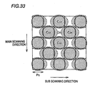
- Fig. 33 shows an arrangement of dots presented for comparison with the dot arrangement shown in Fig. 32.
- dots in each column are displaced by pitch P0 while the print pitch is P0 for both of the main and sub scanning direction.
- the dots are arranged in the pattern of a houndstooth check.
- Fig. 34 shows an example of a structure of a printing apparatus (printer) according to the third embodiment of the invention.
- This printing apparatus is basically the same as the printing apparatus of the first embodiment.
- a data processing unit 51 two types of data to be printed on a card 53 (e.g. data 1 corresponding to a code to be read by means of red radiation and data 2 corresponding to a code to be read by means of green radiation) are input.
- Data processing unit 51 combines the input data in a plurality of types to generate color patterns corresponding to respective combinations.
- Data regarding the generated color patterns is supplied to a printing unit 52.
- Printing unit 52 prints, on card 53, a pattern code formed of a color element corresponding to input data. In this case, a pattern code of a color element, cyan (C), white (W), black (BL), or magenta (M) is printed.
- White used here is the color of a sheet of paper (card) itself.
- Fig. 35 shows a principle on which colors are determined by data processing unit 51.
- code 1 corresponding to data 1 can be read by red radiation and code 2 corresponding to data 2 can be read by green radiation.
- code 1 and code 2 are “1"
- a color element to be printed is white (W).
- a color element to be printed is magenta (M).
- M magenta
- C cyan
- a color element to be printed is black (BL).
- Fig. 36 shows an example of a structure of a reading apparatus for reading card 53 on which a color pattern code is printed as described above.
- a light source 61 generates light in red (R) or green (G) according to a light source switch signal supplied from an image data reading unit control circuit 63 to emit the generated light onto the surface of card 53 with the color pattern code printed thereon.
- a reading device 62 constituted of a CCD imaging unit for example images the color pattern code on card 53 to output a resultant image signal to a data processing unit 64.
- a synchronizing signal synchronized with a reading operation is supplied from image data reading unit control circuit 63.
- Data processing unit 64 binarizes the image signal supplied from reading device 62 to make determination regarding the pattern.
- Reading apparatus When the reading apparatus is commanded by a user to start reading, light source 61 is controlled by image data reading unit control circuit 63 to generate radiation in red at first. Reading device 62 images a pattern code on card 53 irradiated with the red radiation and outputs a resultant image signal to data processing unit 64.
- Reading device 62 images the pattern code on card 53 irradiated with the green radiation and outputs a resultant image signal to data processing unit 64.
- a black pattern read by irradiating the color pattern code with red radiation is directly read as black while a cyan pattern, which is the complementary color of red, that is read with red radiation is also read as a black pattern.
- the color pattern code is read by irradiating the code with green radiation
- the black pattern is directly read as black while a magenta pattern which is the complementary color of green is also read as a black pattern.
- one pattern code can be correlated with two types of codes.
- One of the two codes is defined as an original code and the other is defined as a secret code. Then, copy of the pattern code can be prevented.
- blue radiation can be employed to print one color code by combination of three types of data as shown by an example in Fig. 39.
- code 1 can be read with red radiation
- code 2 can be read with green radiation
- code 3 can be read with blue radiation.
- code 1 and code 3 are all "1" an element is printed in white.
- code 1 and code 2 are “1” and code 3 is "0”, an element is printed in yellow (Y).
- code 1 is “1”
- code 2 is “0” and code 3 is “1”
- an element is printed in magenta (M).
- R red
- Yellow is the complementary color of blue. Then, when a color pattern code is read by irradiating the code with blue radiation, a black pattern is read directly as black while a pattern of yellow which is the complementary color of black is also read as a black pattern. In this case, three types of information can be read from one color pattern code to which the information is allocated.
- the present invention is applicable to pattern codes such as barcode, dot code and various types of two-dimensional codes.
Landscapes
- Physics & Mathematics (AREA)
- General Physics & Mathematics (AREA)
- Engineering & Computer Science (AREA)
- Theoretical Computer Science (AREA)
- Printers Characterized By Their Purpose (AREA)
Abstract
Description
Claims (10)
- A dot code constituted of a plurality of dots, wherein said dots are arranged on the basis of a pitch approximately twice as large as a diameter of a dot.
- A dot code constituted of a plurality of dots, wherein said dots are arranged with a minimum pitch in a region on a reference line and arranged with a pitch longer than the minimum pitch in a remaining region except for the region on the reference line.
- A dot code constituted of a plurality of dots, whereinsaid dots are arranged at respective positions in a region on a reference line and arranged at respective positions corresponding to data in a remaining region except for the region on said reference line, anda region where none of said dots is arranged is formed between said reference line and said remaining region.
- A dot code constituted of a plurality of dots, wherein said dots are colored in colors corresponding to respective positions where said dots are arranged.
- A dot code constituted of a plurality of dots, whereinsaid dot code includes a header section and a data section, andsaid dots have a pitch in said header section set at a greater value than that of a pitch in said data section.
- A two-dimensional code including a header section and a data section wherein an error correction code for said header section has a higher correction capability than that of an error correction code for said data section.
- A dot code constituted of a plurality of dots, wherein said dots are arranged in each column with a pitch approximately twice as large as a diameter of a dot, said dots are arranged in a first column and arranged in a second column adjacent to and apart from said first column by said pitch approximately twice as large as the diameter of a dot, said dots arranged in said second column each being displaced in the direction of said column by almost said diameter of a dot from a position of the dot arranged in said first column.
- A pattern code constituted of a plurality of elements in predetermined colors, whereinsaid colors of the elements are determined to allow said pattern code read with light in a first color to provide a first code and allow said pattern code read with light in a second color to provide a second code.
- A printing apparatus for printing a pattern code constituted of a plurality of elements in predetermined colors on a medium, comprising:capture means for capturing a plurality of data;determination means for determining the predetermined colors by combining the plurality of data captured by said capture means; andprint means for printing said pattern code of said elements in the colors determined by said determination means on said medium.
- A reading apparatus for reading a pattern code constituted of a plurality of elements in predetermined colors from a medium on which said pattern code is printed, comprising:generation means for generating light in a plurality of colors;control means for controlling said generation means to generate light in a predetermined color among the plurality of colors; andreading means for reading a first code from said pattern code on said medium when light in a first color is generated by said generation means and reading a second code from said pattern code on said medium when light in a second color is generated by said generation means.
Applications Claiming Priority (7)
| Application Number | Priority Date | Filing Date | Title |
|---|---|---|---|
| JP9461899 | 1999-04-01 | ||
| JP09461899A JP3642390B2 (en) | 1999-04-01 | 1999-04-01 | Dot code |
| JP11094617A JP2000293644A (en) | 1999-04-01 | 1999-04-01 | Dot code and two-dimensional code |
| JP11094619A JP2000293647A (en) | 1999-04-01 | 1999-04-01 | Pattern code, printing device, and reading device |
| JP9461799 | 1999-04-01 | ||
| JP9461999 | 1999-04-01 | ||
| PCT/JP2000/002093 WO2000060524A1 (en) | 1999-04-01 | 2000-03-31 | Dot code and two-dimensional code |
Publications (2)
| Publication Number | Publication Date |
|---|---|
| EP1178428A1 true EP1178428A1 (en) | 2002-02-06 |
| EP1178428A4 EP1178428A4 (en) | 2004-04-28 |
Family
ID=27307592
Family Applications (1)
| Application Number | Title | Priority Date | Filing Date |
|---|---|---|---|
| EP00913037A Ceased EP1178428A4 (en) | 1999-04-01 | 2000-03-31 | Dot code and two-dimensional code |
Country Status (2)
| Country | Link |
|---|---|
| EP (1) | EP1178428A4 (en) |
| WO (1) | WO2000060524A1 (en) |
Cited By (2)
| Publication number | Priority date | Publication date | Assignee | Title |
|---|---|---|---|---|
| WO2004010368A3 (en) * | 2002-07-12 | 2004-06-03 | Secrypt Gmbh Encryption And Ma | Method for processing a matrix code |
| WO2005055129A1 (en) | 2003-11-14 | 2005-06-16 | Sires Ltd. | Digital information carrier |
Family Cites Families (9)
| Publication number | Priority date | Publication date | Assignee | Title |
|---|---|---|---|---|
| JPS5453018A (en) * | 1977-10-03 | 1979-04-26 | Oki Electric Ind Co Ltd | Type |
| US4263504A (en) * | 1979-08-01 | 1981-04-21 | Ncr Corporation | High density matrix code |
| JPH01142073U (en) * | 1988-03-18 | 1989-09-28 | ||
| US5369261A (en) * | 1992-02-12 | 1994-11-29 | Shamir; Harry | Multi-color information encoding system |
| JPH0830977A (en) * | 1994-07-19 | 1996-02-02 | Olympus Optical Co Ltd | Information recording medium and information recording / reproducing system |
| JP2952170B2 (en) * | 1994-12-16 | 1999-09-20 | オリンパス光学工業株式会社 | Information reproduction system |
| JP3803411B2 (en) * | 1995-12-25 | 2006-08-02 | オリンパス株式会社 | Information reproducing system and information recording medium |
| JPH10283429A (en) * | 1997-04-10 | 1998-10-23 | Mitsubishi Chem Corp | Data code and method of forming the same |
| JP3953144B2 (en) * | 1997-07-16 | 2007-08-08 | オリンパス株式会社 | Code image quality inspection system |
-
2000
- 2000-03-31 EP EP00913037A patent/EP1178428A4/en not_active Ceased
- 2000-03-31 WO PCT/JP2000/002093 patent/WO2000060524A1/en not_active Ceased
Cited By (2)
| Publication number | Priority date | Publication date | Assignee | Title |
|---|---|---|---|---|
| WO2004010368A3 (en) * | 2002-07-12 | 2004-06-03 | Secrypt Gmbh Encryption And Ma | Method for processing a matrix code |
| WO2005055129A1 (en) | 2003-11-14 | 2005-06-16 | Sires Ltd. | Digital information carrier |
Also Published As
| Publication number | Publication date |
|---|---|
| WO2000060524A1 (en) | 2000-10-12 |
| EP1178428A4 (en) | 2004-04-28 |
Similar Documents
| Publication | Publication Date | Title |
|---|---|---|
| US8733874B2 (en) | Printing apparatus and image processing method | |
| EP0776120B1 (en) | Image processing apparatus | |
| US7880929B2 (en) | Image data conversion into substitute ink quantities to differentiate an area in a first image where a second image is embedded | |
| JPH0514683A (en) | Image processing device | |
| US20080317344A1 (en) | Printing apparatus and method with respect to medium | |
| KR100865292B1 (en) | Authenticity determination method, apparatus, and computer readable recording medium recording a program | |
| EP0905965A2 (en) | Ink-jet copier in which an original image is prescanned for optimized printing | |
| US8223392B2 (en) | Image processing device and image processing method | |
| JP5656370B2 (en) | Image processing apparatus, image processing system, image processing method, and program | |
| US10430974B2 (en) | Image processing apparatus, image processing method, and storage medium | |
| US20250001768A1 (en) | Image forming apparatus | |
| EP3467715B1 (en) | Two-dimensional code composed of a plurality of types of cells | |
| US12325234B2 (en) | Image forming apparatus | |
| JP5129539B2 (en) | RECORDING FAILURE DETECTING DEVICE, IMAGE RECORDING DEVICE, AND RECORDING FAILURE DETECTING METHOD | |
| US20040039982A1 (en) | Dot code and dot code reader | |
| WO2000060524A1 (en) | Dot code and two-dimensional code | |
| US11196898B2 (en) | Image reading apparatus, method of controlling image reading apparatus, and storage medium | |
| JP2005271369A (en) | Image forming device and method of correcting image forming position | |
| JP4872500B2 (en) | Image reading device | |
| US12028496B2 (en) | Multi-mode scanning camera system and method | |
| JP2000293644A (en) | Dot code and two-dimensional code | |
| JP2885799B2 (en) | Image processing device | |
| JP3642390B2 (en) | Dot code | |
| JP5222884B2 (en) | Optical character reader | |
| JP2007281791A (en) | Image reading apparatus and image reading method |
Legal Events
| Date | Code | Title | Description |
|---|---|---|---|
| PUAI | Public reference made under article 153(3) epc to a published international application that has entered the european phase |
Free format text: ORIGINAL CODE: 0009012 |
|
| 17P | Request for examination filed |
Effective date: 20011029 |
|
| AK | Designated contracting states |
Kind code of ref document: A1 Designated state(s): AT BE CH CY DE DK ES FI FR GB GR IE IT LI LU MC NL PT SE |
|
| RIN1 | Information on inventor provided before grant (corrected) |
Inventor name: CHUJO, HIDEKI OMRON CORP. 801, MINAMIFUDOUDOU-CHO Inventor name: MATSUMURA, MITSURU OM.CORP. 801 MINAMIFUDOUDOU-CH Inventor name: KAKIUCHI, TAKASHI OM. CORP. 801 MINAMIFUDOUDOU-CH Inventor name: NISHIO, GOKI OMRON CORP. 801, MINAMIFUDOUDOU-CHO |
|
| A4 | Supplementary search report drawn up and despatched |
Effective date: 20040311 |
|
| RIC1 | Information provided on ipc code assigned before grant |
Ipc: 7G 06K 19/06 A |
|
| RBV | Designated contracting states (corrected) |
Designated state(s): DE FR GB IT |
|
| 17Q | First examination report despatched |
Effective date: 20040826 |
|
| STAA | Information on the status of an ep patent application or granted ep patent |
Free format text: STATUS: THE APPLICATION HAS BEEN REFUSED |
|
| 18R | Application refused |
Effective date: 20051105 |