EP1178244A2 - Shift control system for automatic transmission - Google Patents
Shift control system for automatic transmission Download PDFInfo
- Publication number
- EP1178244A2 EP1178244A2 EP01118610A EP01118610A EP1178244A2 EP 1178244 A2 EP1178244 A2 EP 1178244A2 EP 01118610 A EP01118610 A EP 01118610A EP 01118610 A EP01118610 A EP 01118610A EP 1178244 A2 EP1178244 A2 EP 1178244A2
- Authority
- EP
- European Patent Office
- Prior art keywords
- lower limit
- gear ratio
- shift
- range
- automatic transmission
- Prior art date
- Legal status (The legal status is an assumption and is not a legal conclusion. Google has not performed a legal analysis and makes no representation as to the accuracy of the status listed.)
- Withdrawn
Links
Images





Classifications
-
- F—MECHANICAL ENGINEERING; LIGHTING; HEATING; WEAPONS; BLASTING
- F16—ENGINEERING ELEMENTS AND UNITS; GENERAL MEASURES FOR PRODUCING AND MAINTAINING EFFECTIVE FUNCTIONING OF MACHINES OR INSTALLATIONS; THERMAL INSULATION IN GENERAL
- F16H—GEARING
- F16H61/00—Control functions within control units of change-speed- or reversing-gearings for conveying rotary motion ; Control of exclusively fluid gearing, friction gearing, gearings with endless flexible members or other particular types of gearing
- F16H61/02—Control functions within control units of change-speed- or reversing-gearings for conveying rotary motion ; Control of exclusively fluid gearing, friction gearing, gearings with endless flexible members or other particular types of gearing characterised by the signals used
- F16H61/0202—Control functions within control units of change-speed- or reversing-gearings for conveying rotary motion ; Control of exclusively fluid gearing, friction gearing, gearings with endless flexible members or other particular types of gearing characterised by the signals used the signals being electric
- F16H61/0204—Control functions within control units of change-speed- or reversing-gearings for conveying rotary motion ; Control of exclusively fluid gearing, friction gearing, gearings with endless flexible members or other particular types of gearing characterised by the signals used the signals being electric for gearshift control, e.g. control functions for performing shifting or generation of shift signal
- F16H61/0213—Control functions within control units of change-speed- or reversing-gearings for conveying rotary motion ; Control of exclusively fluid gearing, friction gearing, gearings with endless flexible members or other particular types of gearing characterised by the signals used the signals being electric for gearshift control, e.g. control functions for performing shifting or generation of shift signal characterised by the method for generating shift signals
-
- F—MECHANICAL ENGINEERING; LIGHTING; HEATING; WEAPONS; BLASTING
- F16—ENGINEERING ELEMENTS AND UNITS; GENERAL MEASURES FOR PRODUCING AND MAINTAINING EFFECTIVE FUNCTIONING OF MACHINES OR INSTALLATIONS; THERMAL INSULATION IN GENERAL
- F16H—GEARING
- F16H61/00—Control functions within control units of change-speed- or reversing-gearings for conveying rotary motion ; Control of exclusively fluid gearing, friction gearing, gearings with endless flexible members or other particular types of gearing
- F16H61/66—Control functions within control units of change-speed- or reversing-gearings for conveying rotary motion ; Control of exclusively fluid gearing, friction gearing, gearings with endless flexible members or other particular types of gearing specially adapted for continuously variable gearings
- F16H61/662—Control functions within control units of change-speed- or reversing-gearings for conveying rotary motion ; Control of exclusively fluid gearing, friction gearing, gearings with endless flexible members or other particular types of gearing specially adapted for continuously variable gearings with endless flexible members
- F16H61/66254—Control functions within control units of change-speed- or reversing-gearings for conveying rotary motion ; Control of exclusively fluid gearing, friction gearing, gearings with endless flexible members or other particular types of gearing specially adapted for continuously variable gearings with endless flexible members controlling of shifting being influenced by a signal derived from the engine and the main coupling
- F16H61/66259—Control functions within control units of change-speed- or reversing-gearings for conveying rotary motion ; Control of exclusively fluid gearing, friction gearing, gearings with endless flexible members or other particular types of gearing specially adapted for continuously variable gearings with endless flexible members controlling of shifting being influenced by a signal derived from the engine and the main coupling using electrical or electronical sensing or control means
-
- F—MECHANICAL ENGINEERING; LIGHTING; HEATING; WEAPONS; BLASTING
- F16—ENGINEERING ELEMENTS AND UNITS; GENERAL MEASURES FOR PRODUCING AND MAINTAINING EFFECTIVE FUNCTIONING OF MACHINES OR INSTALLATIONS; THERMAL INSULATION IN GENERAL
- F16H—GEARING
- F16H61/00—Control functions within control units of change-speed- or reversing-gearings for conveying rotary motion ; Control of exclusively fluid gearing, friction gearing, gearings with endless flexible members or other particular types of gearing
- F16H61/66—Control functions within control units of change-speed- or reversing-gearings for conveying rotary motion ; Control of exclusively fluid gearing, friction gearing, gearings with endless flexible members or other particular types of gearing specially adapted for continuously variable gearings
- F16H2061/6604—Special control features generally applicable to continuously variable gearings
- F16H2061/6615—Imitating a stepped transmissions
- F16H2061/6616—Imitating a stepped transmissions the shifting of the transmission being manually controlled
-
- F—MECHANICAL ENGINEERING; LIGHTING; HEATING; WEAPONS; BLASTING
- F16—ENGINEERING ELEMENTS AND UNITS; GENERAL MEASURES FOR PRODUCING AND MAINTAINING EFFECTIVE FUNCTIONING OF MACHINES OR INSTALLATIONS; THERMAL INSULATION IN GENERAL
- F16H—GEARING
- F16H61/00—Control functions within control units of change-speed- or reversing-gearings for conveying rotary motion ; Control of exclusively fluid gearing, friction gearing, gearings with endless flexible members or other particular types of gearing
- F16H61/66—Control functions within control units of change-speed- or reversing-gearings for conveying rotary motion ; Control of exclusively fluid gearing, friction gearing, gearings with endless flexible members or other particular types of gearing specially adapted for continuously variable gearings
- F16H61/664—Friction gearings
- F16H2061/6641—Control for modifying the ratio control characteristic
- F16H2061/6643—Control for modifying the ratio control characteristic dependent on driver's choice
-
- F—MECHANICAL ENGINEERING; LIGHTING; HEATING; WEAPONS; BLASTING
- F16—ENGINEERING ELEMENTS AND UNITS; GENERAL MEASURES FOR PRODUCING AND MAINTAINING EFFECTIVE FUNCTIONING OF MACHINES OR INSTALLATIONS; THERMAL INSULATION IN GENERAL
- F16H—GEARING
- F16H59/00—Control inputs to control units of change-speed- or reversing-gearings for conveying rotary motion
- F16H59/14—Inputs being a function of torque or torque demand
- F16H59/24—Inputs being a function of torque or torque demand dependent on the throttle opening
-
- F—MECHANICAL ENGINEERING; LIGHTING; HEATING; WEAPONS; BLASTING
- F16—ENGINEERING ELEMENTS AND UNITS; GENERAL MEASURES FOR PRODUCING AND MAINTAINING EFFECTIVE FUNCTIONING OF MACHINES OR INSTALLATIONS; THERMAL INSULATION IN GENERAL
- F16H—GEARING
- F16H59/00—Control inputs to control units of change-speed- or reversing-gearings for conveying rotary motion
- F16H59/36—Inputs being a function of speed
- F16H59/44—Inputs being a function of speed dependent on machine speed, e.g. the vehicle speed
Definitions
- the present invention relates to a shift control system of an automatic transmission for a vehicle.
- Japanese Patent Application Laid-open No. 7-301321 discloses an example of a shift control system of an automatic transmission for a vehicle.
- this conventional system is provided with an automatic shift mode and a manual shift mode.
- a manual shift mode When a manual shift mode is selected, an upshift operation and a downshift operation are performed by the driver's shift operation, and thus gear ratios are continuously controlled by the driver's manual operation.
- gear ratios are continuously controlled by the driver's manual operation.
- a shift lever is placed in a neutral position between an upshift and a downshift, a gear ratio is fixed. This makes it possible to adjust driving force and engine braking force continuously and to perform a speed change operation in accordance with the driver's intention.
- the present invention has been made in view of the aforementioned problem, and its object is to provide a shift control system of an automatic transmission capable of performing a speed change operation in accordance with intention of a driver and also changing speed without performing a troublesome shift operation.
- a shift control system for an automatic transmission which has a gear ratio control means for controlling gear ratio of the automatic transmission by determining a target gear ratio from a drive point determined on the basis of at least a throttle opening and a vehicle speed, comprising a lower limit setting device provided in the gear ratio control means and setting a lower limit for inhibiting a gear ratio from changing to a gear ratio of an upshift side; and a lower limit variable control means in which a lower limit of the gear ratio can be changed to a downshift side or to an upshift side by an operation of a driver.
- the shift control system may change a control state between first state in which an automatic shift can be performed regardless of the lower limit and second state in which an automatic shift can be performed within a gear ratio range which is not below the lower limit.
- the lower limit setting device of the gear ratio control means sets a gear ratio at the time of changing from the first state in which an automatic shift can be performed regardless of the lower limit into the second state in which an automatic shift can be performed within a gear ratio range which is not below the lower limit, as the lower limit.
- the lower limit variable control means includes a lowest side limiting ratio for restricting a change range of a downshift side of the lower limit, a highest side limiting ratio for restricting a change range of an upshift side of the lower limit and a speed upper limit of a transmission input shaft within a change range of the lower limit, and when a speed of the transmission input shaft reaches the speed upper limit due to a gear ratio selected within the change range, the lower limit variable control means inhibits the lower limit from shifting from the selected gear ratio to a gear ratio of a downshift side, and when a speed of the transmission input shaft exceeds the speed upper limit, the lower limit variable control means shifts the lower limit to a gear ratio of an upshift side that does not cause the speed of said transmission input shaft to exceed said speed upper limit.
- an excessive engine brake can be suppressed, and also a so-called over revolution, that is, a state where the engine rotates excessively, can be inhibited.
- the shift control system is equipped with a speed changeable range indicating means for indicating an allowable shift range to a driver when the lower limit variable control means controls a lower limit variably.
- the driver can recognize a position of the lower limit and the allowable shift range.
- the shift control system is equipped with a gear ratio selecting means capable of selecting gear ratios by the driver's shift operation, and changeable a lower limit for the lower limit variable control means by the shift operation thereof; and a switching means for switching between a shift control by the gear ratio selecting means according to the shift operation and a shift control by the lower limit variable control means according to the shift operation.
- the shift control system is equipped with a selection condition indicating means for indicating whether the lower limit variable control is selected.
- the driver can recognize that a lower limit variable control is selected even during running in the "D" range.
- the lower limit variable control means inhibits a lower limit variable control at the time of activation of an anti lock brake system (ABS) for preventing wheels from being locked or slipping due to the drivers hard braking.
- ABS anti lock brake system
- the automatic transmission is a continuously variable transmission for selecting gear ratios continuously; and the lower limit variable control means changes a lower limit continuously in case where a lower limit change operation is continued for a certain period of time by the driver at the time of change of a lower limit of a gear ratio.
- the driver can change the lower limit continuously while feeling a desired engine braking force. Since shift operation is limited to the adjustment of engine braking force and others, moreover, this shift operation is not troublesome to the driver.
- Fig. 1 is a block diagram of a system of a vehicle to which a shift control system according to the embodiment of the invention is applied.
- a shift lever 3 selects a drive range ("D" range), a manual range ("M” range), a manual “+” range (“M+” range) and a manual "-” range ("M-” range).
- a change-over switch 7 switches a manual control and a limit line variable control and may be provided in a monitor of a navigation system mounted on a vehicle or may be provided in the shift lever 3.
- An ABS flag 9 outputs a signal for determining an inhibition of a limit line variable control at the time of activation of an ABS.
- a CVT control unit 14 controls a gear ratio of a belt-type continuously variable transmission (CVT) 1 to achieve a target gear ratio.
- the CVT control unit 14 determines a target gear ratio from a shift map 2, and outputs a command of achieving the target gear ratio to a hydraulic control valve unit 15 acting as a gear ratio actuator.
- This CVT control unit 14 constitutes a servo system performing a feedback control so that an actual gear ratio coincides with a target gear ratio.
- a shift range indicator 6 includes a limit line variable control selection condition indicator 8 and shows whether a limit line variable control is selected.
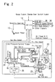
- Fig. 2 is a diagram showing a belt-type continuously variable transmission and a shift control system according to the embodiment.
- a torque converter 20 which includes a lock-up clutch 21 for connecting the engine and the belt-type CVT 1 directly by engagement.
- the output side of the torque converter 20 is coupled to a transmission input shaft 26.
- One end of this input shaft 26 is provided with primary pulleys 27, 28 of the belt-type CVT 1.
- the belt-type CVT 1 is comprised of the aforementioned primary pulleys 27, 28, secondary pulleys 29, 30 and a belt 31 transmitting torque of the primary pulleys 27, 28 to the secondary pulleys 29, 30.
- a movable primary pulley 28 can be moved in the axial direction of the input shaft 26 by primary hydraulic pressure acting on a primary pulley cylinder chamber 32.
- a movable secondary pulley 30 can be moved in the axial direction of an output shaft 34 by secondary hydraulic pressure acting on a secondary pulley cylinder chamber 33.
- To the output shaft 34 there is firmly fitted a not-shown drive gear which drives a drive shaft extending to wheels via a pinion mounted on an idler shaft, a final gear and a differential gear unit.
- a revolution speed of the secondary pulleys 29, 30 is proportional to a vehicle speed. Therefore, in the CVT control unit 14 a target gear ratio is calculated based on the primary revolution speed (revolution speed of the primary pulleys) obtained from the shift map 2.
- the control for changing the width of V-shaped pulley grooves of these primary pulleys 27, 28 and secondary pulleys 29, 30 is performed by supplying primary hydraulic pressure and secondary hydraulic pressure, which is produced by the hydraulic pressure control valve unit 15 in accordance with command from the CVT control unit 14, to the primary pulley cylinder chamber 32 and the second pulley cylinder chamber 33 respectively.
- the CVT control unit 14 receives a limit line variable control command from the change-over switch 7.
- This CVT control unit 14 receives a throttle opening signal from a throttle opening sensor 10, a switch signal from a kick-down switch 35, a vehicle speed signal from a vehicle speed sensor 36, a transmission oil temperature signal from an oil temperature sensor 37, a primary revolution speed signal from a primary speed sensor 22, a secondary revolution speed signal from a secondary speed sensor 23, a range signal from the shift lever 3 and others.
- the CVT control unit 14 performs arithmetic processing on the basis of these input signals and outputs a line pressure control signal to a line pressure solenoid 24 and outputs a gear ratio control signal to the hydraulic pressure control valve unit 15 and outputs an oil pump unit control signal to an oil pump unit 25.
- Fig. 3 is an enlarged view of the shift lever 3 according to the embodiment of the invention.
- the "M" range (manual mode) is selected by moving a shift knob 3a in a lateral direction from the "D" range position.
- the shift knob 3a has the change-over switch 7 for switching a normal manual mode to a limit line (a lower limit of gear ratio) variable mode. When this change-over switch 7 is ON, the shift knob 3a is moved to the "M+" range or the "M-" range so that a limit line of gear ratio can be varied.
- Fig. 5 is a flow chart showing a limit line variable control by the CVT control unit 14 according to the embodiment of the invention.
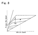
- step 101 it is determined whether the change over switch 7 for a limit line variable control is turned on. If turned ON, the routine proceeds to step 102. If turned OFF, the routine proceeds to step 114, and a normal manual shift control using a shift map as shown in Fig. 8 is performed.
- step 102 it is determined from the ABS flag 9 whether the ABS is not activated. If the result is affirmative, the routine proceeds to step 103. If the result is negative, the routine proceeds to the step 114.
- step 103 it is determined whether a range signal produced by the shift lever 3 is indicative of the "M" range position (manual mode). If the result is affirmative, the routine proceeds to step 104. If the signal is indicative of other positions, the routine proceeds to the step 106.
- step 104 it is determined whether the lever is positioned at the "M" range first time. If this is the case, the routine proceeds to step 105. If this is not the case, the routine proceeds to step 110.
- a value DRATIOlim of a gear ratio for limiting a high ratio side of a "D" range shift line is set as a highest limiting ratio.
- step 106 it is determined whether a range signal produced by the shift lever 3 is indicative of the "M-" range. If the result is affirmative, the routine proceeds to step 107. If the result is negative, the routine proceeds to step 108.
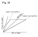
- a regulation control in a low ratio side is performed (see Figs. 6 and 10).
- step 108 it is determined whether a range signal produced by the shift lever 3 is indicative of the "M+" range. If the result is affirmative, the routine proceeds to step 109. If the result is negative, the routine proceeds to the step 114.
- a regulation control in a high ratio side is performed (see Figs. 7 and 10).
- step 111 it is determined whether the value of the gear ratio (DRATIOlim) is such that a primary revolution speed is kept under an upper limit value. If the result is affirmative, the routine proceeds to step 112. If the result is negative, the routine proceeds to step 113.
- DRATIOlim gear ratio
- a gear ratio command is executed.
- the value DRATIOlim is shifted to a high ratio side so that the primary revolution speed does not exceed the upper limit value (see Fig. 11B).
- a normal shift control is performed. More specifically, if the change-over switch 7 for switching between a limit line variable control and a manual mode is turned ON, it is determined from the ABS flag whether the ABS is activated. This is aimed that the wheels can be prevented from being locked when engine braking force is applied by means of the regulation of limit lines. If the ABS is activated or the change-over switch 7 is OFF, a normal shift control is performed, as shown in Fig. 8.
- a gear ratio DRATIOlim for limiting a high ratio side in the "D" range shift line is set as the highest limiting ratio. More specifically, if the driver turns the change-over switch 7 ON and merely selects the "M” range and never selects the "M+” range and the "M-” range, a gear ratio at that time is set as a highest gear ratio, and thereby shift shock at the time of switching controls can be eliminated.
- step 72 it is determined whether the value DRATIOlim is less than a lowest limiting ratio. If the result is affirmative, the routine proceeds to step 73, and it is commanded to shift the value DRATIOlim to a low ratio side. If the result is negative, the value DRATIOlim is maintained in step 74. In short, even if the driver attempts to shift a limit line to a low ratio side, the value DRATIOlim is limited to the lowest limiting ratio so as to prevent the engine brake from working excessively.
- step 92 it is determined whether the value DRATIOlim is more than the highest limiting ratio. If the result is affirmative, the routine proceeds to step 93 and it is commanded to shift the value DRATIOlim to a high ratio side. If the result is negative, the routine proceeds to step 94 to maintain the value DRATIOlim.
- the value DRATIOlim is limited to the highest limiting ratio, whereby a limit line can be prevented from being unnecessarily shifted to a higher ratio side than a shift range, as in the case where the value DRATIOlim is limited to the aforementioned lowest limiting ratio.
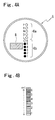
- the shift range indicator 6 is provided with a shift position indicator 6a for showing shift positions, a limit line variable control selection condition indicator 8 for showing whether a limit line variable control is selected, and a gear ratio indicator 6b for showing gear ratios.
- a shift range allowable in a limit line variable control is indicated. Thereby, the driver can recognize a position of a limit line and a shiftable range.
- Fig. 4B shows another example of gear ratio indicator.
- the lamps are constituted with rectangular segment lamps "a" to "n+1", number of which is larger than that of the gear ratio indicator 6b in Fig. 4A. Therefore, the shift range allowable in a limit line variable control is more precisely indicated.
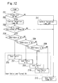
- Fig. 12 is a flow chart showing a control of an indicating system of case where a limit line variable control is performed.
- the gear ratio indicator shown in Fig.4B is controlled.
- step 201 it is determined whether the change-over switch 7 is turned ON. If turned ON, the routine proceeds to step 202. If turned OFF, the routine proceeds to step 211.
- a limit line variable control selection lamp is turned ON.
- step 203 it is determined whether the shift knob 3a is placed on the "M" range position. If the result is affirmative, the routine proceeds to step 204. If the result is negative, the routine proceeds to step 212.
- step 204 it is determined whether the value DRATIOlim is more than a gear ratio A. If the result is affirmative, the routine proceeds to step 205 and the lamp "a" of a gear ratio indicator is turned on. If this is not the case, the routine proceeds to step 206.
- step 206 it is determined whether the value DRATIOlim is more than a gear ratio B. If the result is affirmative, the routine proceeds to step 207 and the lamps "a" - “b" of the gear ratio indicator are turned on. Thereafter, such an operation is repeated, and lamps "a" - “n” of the gear ratio indicator are sequentially turned on according to the value DRATIOlim.
- step 211 the limit line variable control selection lamp is turned off. Then, the routine proceeds to step 212, and all lamps of the gear ratio indicator are turned off.
- a limit line for setting a lower limit for inhibiting a gear ratio from changing from a gear stage to an upshift side.
- the shift lever 3 can change the limit line to a downshift side or an upshift side.
- the driver can set a limit line and change the limit line to a downshift side or an upshift side with the shift lever 3, thereby controlling a lower limit of a gear ratio. Therefore, if a limit line is set with respect to a gear ratio, a "D" range running can be performed on a lower ratio side than the set gear ratio. Since a normal running in the "D" range can be also performed, the driver's shift operation can be simplified. By the provision of the belt-type CVT 1, the driver can change the limit lines continuously while feeling desired engine braking force. Since shift operations are limited to the adjustments of engine braking force and others, this shift operation is not troublesome to the driver.
- the limit line can be prevented from being unnecessarily changed to an upshift side rather than a shift range.
- a speed upper limit of the transmission input shaft within a change range of the limit line.
- the shift range indicator 8 indicates a shiftable range to the driver when a limit line is variably controlled, the driver can recognize the position of a limit line and the shiftable range.
- the conventional manual shift control device as it is can be used as a changing section for a limit line variable control, and both the conventional manual range and the limit line variable control can be operated with a single shift lever.
- the driver can recognize that the limit line variable control is selected, even during the running in the "D" range.
- the anti-lock brake system is activated to avoid the locking of wheels at the time of a sudden braking or a slipping state of the wheels.
- the wheels can be prevented from being locked due to an excessive engine braking force when the ABS is activated.
Landscapes
- Engineering & Computer Science (AREA)
- General Engineering & Computer Science (AREA)
- Mechanical Engineering (AREA)
- Control Of Transmission Device (AREA)
Abstract
Description
- The present invention relates to a shift control system of an automatic transmission for a vehicle.
- Japanese Patent Application Laid-open No. 7-301321 discloses an example of a shift control system of an automatic transmission for a vehicle. As disclosed, this conventional system is provided with an automatic shift mode and a manual shift mode. When a manual shift mode is selected, an upshift operation and a downshift operation are performed by the driver's shift operation, and thus gear ratios are continuously controlled by the driver's manual operation. On the other hand, when a shift lever is placed in a neutral position between an upshift and a downshift, a gear ratio is fixed. This makes it possible to adjust driving force and engine braking force continuously and to perform a speed change operation in accordance with the driver's intention.
- However, a problem with the aforementioned conventional shift control system of an automatic transmission is that shift operation must be always performed in order to obtain a desired engine speed and driving force while vehicle speed changes variously.
- The present invention has been made in view of the aforementioned problem, and its object is to provide a shift control system of an automatic transmission capable of performing a speed change operation in accordance with intention of a driver and also changing speed without performing a troublesome shift operation.
- In order to achieve the above object, according to an aspect of the invention, there is provided a shift control system for an automatic transmission which has a gear ratio control means for controlling gear ratio of the automatic transmission by determining a target gear ratio from a drive point determined on the basis of at least a throttle opening and a vehicle speed, comprising a lower limit setting device provided in the gear ratio control means and setting a lower limit for inhibiting a gear ratio from changing to a gear ratio of an upshift side; and a lower limit variable control means in which a lower limit of the gear ratio can be changed to a downshift side or to an upshift side by an operation of a driver.
- In the aspect of the invention, by setting a lower limit of a gear ratio and changing this lower limit by the driver's operation, engine braking force can be optionally obtained and a running in a "D" range can be performed at a lower ratio side than the set lower limit. In the automatic transmission having a conventional manual shift function, shift operation must be always performed in order to obtain a desired engine speed and driving force while vehicle speeds changes variously. On the other hand, according to the invention, even in case a lower limit of a selected gear ratio is set, a normal running in the "D" range can be performed within a range of a lower ratio side than the selected gear ratio, and therefore the driver's shift operation load can be reduced.
- In the preferred embodiment, the shift control system may change a control state between first state in which an automatic shift can be performed regardless of the lower limit and second state in which an automatic shift can be performed within a gear ratio range which is not below the lower limit.
- As a result, it is possible to perform gear ratio controls that reflect the driver's intention more sufficiently.
- Preferably, the lower limit setting device of the gear ratio control means sets a gear ratio at the time of changing from the first state in which an automatic shift can be performed regardless of the lower limit into the second state in which an automatic shift can be performed within a gear ratio range which is not below the lower limit, as the lower limit.
- As a result, it is possible to avoid occurrence of shift shocks when the automatic gear ratio control is shifted to the lower limit variable control.
- Further preferably, the lower limit variable control means includes a lowest side limiting ratio for restricting a change range of a downshift side of the lower limit, a highest side limiting ratio for restricting a change range of an upshift side of the lower limit and a speed upper limit of a transmission input shaft within a change range of the lower limit, and when a speed of the transmission input shaft reaches the speed upper limit due to a gear ratio selected within the change range, the lower limit variable control means inhibits the lower limit from shifting from the selected gear ratio to a gear ratio of a downshift side, and when a speed of the transmission input shaft exceeds the speed upper limit, the lower limit variable control means shifts the lower limit to a gear ratio of an upshift side that does not cause the speed of said transmission input shaft to exceed said speed upper limit.
- As a result, an excessive engine brake can be suppressed, and also a so-called over revolution, that is, a state where the engine rotates excessively, can be inhibited.
- Further preferably, the shift control system is equipped with a speed changeable range indicating means for indicating an allowable shift range to a driver when the lower limit variable control means controls a lower limit variably.
- As a result, the driver can recognize a position of the lower limit and the allowable shift range.
- Further preferably, the shift control system is equipped with a gear ratio selecting means capable of selecting gear ratios by the driver's shift operation, and changeable a lower limit for the lower limit variable control means by the shift operation thereof; and a switching means for switching between a shift control by the gear ratio selecting means according to the shift operation and a shift control by the lower limit variable control means according to the shift operation.
- Thereby, since the conventional manual shift device as it is becomes able to be used as a changing device for a lower limit variable control, both operations of a conventional manual range and a lower limit variable control can be performed with one shift lever.
- Further preferably, the shift control system is equipped with a selection condition indicating means for indicating whether the lower limit variable control is selected.
- As a result, the driver can recognize that a lower limit variable control is selected even during running in the "D" range.
- Further preferably, the lower limit variable control means inhibits a lower limit variable control at the time of activation of an anti lock brake system (ABS) for preventing wheels from being locked or slipping due to the drivers hard braking.
- As a result, it is possible to prevent the wheels from being locked or slipping due to an excessive engine braking force when the anti-lock brake system is activated.
- Still further preferably, the automatic transmission is a continuously variable transmission for selecting gear ratios continuously; and the lower limit variable control means changes a lower limit continuously in case where a lower limit change operation is continued for a certain period of time by the driver at the time of change of a lower limit of a gear ratio.
- As a result, the driver can change the lower limit continuously while feeling a desired engine braking force. Since shift operation is limited to the adjustment of engine braking force and others, moreover, this shift operation is not troublesome to the driver.
- The above and further objects and features of the invention will be more fully apparent from the following description when the same is considered with reference to the accompanying drawings.
-
- Fig. 1 is a block diagram showing a system of a vehicle to which a shift control system according to the embodiment of the invention is applied.
- Fig. 2 is a diagram showing a belt-type continuously variable transmission and a shift control system according to the embodiment of the invention.
- Fig. 3 is a schematic diagram of a shift lever according to the embodiment of the invention.
- Fig. s 4A and 4B are diagrams showing a shift range indicator according to the embodiment of the invention.
- Fig. 5 is a flow chart showing a limit line variable control according to the embodiment of the invention.
- Fig. 6 is a flow chart showing a regulation control of a low ratio side according to the embodiment of the invention.
- Fig. 7 is a flow chart showing a regulation control of a high ratio side according to the embodiment of the invention.
- Fig. 8 is a shift map for an ordinary control in a "D" range according to the embodiment of the invention.
- Fig. 9 is a shift map for a limit line variable control according to the embodiment of the invention.
- Fig. 10 is a shift map for a limit line variable control according to the embodiment of the invention.
- Fig.s 11A and 11B shows a change of limit line in a limit line variable control according to the embodiment of the invention.
- Fig. 12 is a flow chart showing a display control at the time of a limit line variable control according to the embodiment of the invention.
-
- Here will be described the embodiment of the invention with reference to the accompanying drawings.
- Fig. 1 is a block diagram of a system of a vehicle to which a shift control system according to the embodiment of the invention is applied.
- As shown in Fig. 1, a shift lever 3 (see Fig. 3) selects a drive range ("D" range), a manual range ("M" range), a manual "+" range ("M+" range) and a manual "-" range ("M-" range). A change-
over switch 7 switches a manual control and a limit line variable control and may be provided in a monitor of a navigation system mounted on a vehicle or may be provided in theshift lever 3. An ABS flag 9 outputs a signal for determining an inhibition of a limit line variable control at the time of activation of an ABS. - A
CVT control unit 14 controls a gear ratio of a belt-type continuously variable transmission (CVT) 1 to achieve a target gear ratio. TheCVT control unit 14 determines a target gear ratio from ashift map 2, and outputs a command of achieving the target gear ratio to a hydrauliccontrol valve unit 15 acting as a gear ratio actuator. ThisCVT control unit 14 constitutes a servo system performing a feedback control so that an actual gear ratio coincides with a target gear ratio. - A
shift range indicator 6 includes a limit line variable controlselection condition indicator 8 and shows whether a limit line variable control is selected. - Fig. 2 is a diagram showing a belt-type continuously variable transmission and a shift control system according to the embodiment.
- To an output shaft of the engine, there is coupled a
torque converter 20 which includes a lock-up clutch 21 for connecting the engine and the belt-type CVT 1 directly by engagement. - The output side of the
torque converter 20 is coupled to atransmission input shaft 26. One end of thisinput shaft 26 is provided with primary pulleys 27, 28 of the belt-type CVT 1. - The belt-
type CVT 1 is comprised of the aforementioned primary pulleys 27, 28,secondary pulleys belt 31 transmitting torque of the primary pulleys 27, 28 to thesecondary pulleys input shaft 26 by primary hydraulic pressure acting on a primarypulley cylinder chamber 32. Of thesecondary pulleys secondary pulley 30 can be moved in the axial direction of anoutput shaft 34 by secondary hydraulic pressure acting on a secondarypulley cylinder chamber 33. To theoutput shaft 34, there is firmly fitted a not-shown drive gear which drives a drive shaft extending to wheels via a pinion mounted on an idler shaft, a final gear and a differential gear unit. - By moving the movable primary pulley 28 and the movable
secondary pulley 30 in their respective axial directions and changing radii of these pulleys coming into contact with thebelt 31, a revolution speed ratio of the primary pulleys 27, 28 to thesecondary pulleys 29, 30(inverse of pulley ratio), that is, a gear ratio can be changed. - Since the
secondary pulleys output shaft 34 which is connected to the wheels, a revolution speed of thesecondary pulleys shift map 2. - The control for changing the width of V-shaped pulley grooves of these primary pulleys 27, 28 and
secondary pulleys control valve unit 15 in accordance with command from theCVT control unit 14, to the primarypulley cylinder chamber 32 and the secondpulley cylinder chamber 33 respectively. - The
CVT control unit 14 receives a limit line variable control command from the change-overswitch 7. ThisCVT control unit 14 receives a throttle opening signal from athrottle opening sensor 10, a switch signal from a kick-down switch 35, a vehicle speed signal from avehicle speed sensor 36, a transmission oil temperature signal from anoil temperature sensor 37, a primary revolution speed signal from aprimary speed sensor 22, a secondary revolution speed signal from asecondary speed sensor 23, a range signal from theshift lever 3 and others. TheCVT control unit 14 performs arithmetic processing on the basis of these input signals and outputs a line pressure control signal to aline pressure solenoid 24 and outputs a gear ratio control signal to the hydraulic pressurecontrol valve unit 15 and outputs an oil pump unit control signal to anoil pump unit 25. - Fig. 3 is an enlarged view of the
shift lever 3 according to the embodiment of the invention. The "M" range (manual mode) is selected by moving ashift knob 3a in a lateral direction from the "D" range position. Theshift knob 3a has the change-overswitch 7 for switching a normal manual mode to a limit line (a lower limit of gear ratio) variable mode. When this change-overswitch 7 is ON, theshift knob 3a is moved to the "M+" range or the "M-" range so that a limit line of gear ratio can be varied. - Fig. 5 is a flow chart showing a limit line variable control by the
CVT control unit 14 according to the embodiment of the invention. - At
step 101, it is determined whether the change overswitch 7 for a limit line variable control is turned on. If turned ON, the routine proceeds to step 102. If turned OFF, the routine proceeds to step 114, and a normal manual shift control using a shift map as shown in Fig. 8 is performed. - At the
step 102, it is determined from the ABS flag 9 whether the ABS is not activated. If the result is affirmative, the routine proceeds to step 103. If the result is negative, the routine proceeds to thestep 114. - At the
step 103, it is determined whether a range signal produced by theshift lever 3 is indicative of the "M" range position (manual mode). If the result is affirmative, the routine proceeds to step 104. If the signal is indicative of other positions, the routine proceeds to thestep 106. - At the
step 104, it is determined whether the lever is positioned at the "M" range first time. If this is the case, the routine proceeds to step 105. If this is not the case, the routine proceeds to step 110. - At the
step 105, a value DRATIOlim of a gear ratio for limiting a high ratio side of a "D" range shift line is set as a highest limiting ratio. - At the
step 106, it is determined whether a range signal produced by theshift lever 3 is indicative of the "M-" range. If the result is affirmative, the routine proceeds to step 107. If the result is negative, the routine proceeds to step 108. - At the
step 107, a regulation control in a low ratio side is performed (see Figs. 6 and 10). - At the
step 108, it is determined whether a range signal produced by theshift lever 3 is indicative of the "M+" range. If the result is affirmative, the routine proceeds to step 109. If the result is negative, the routine proceeds to thestep 114. - At the
step 109, a regulation control in a high ratio side is performed (see Figs. 7 and 10). - At the
step 110, it is commanded to maintain the value DRATIOlim. - At
step 111, it is determined whether the value of the gear ratio (DRATIOlim) is such that a primary revolution speed is kept under an upper limit value. If the result is affirmative, the routine proceeds to step 112. If the result is negative, the routine proceeds to step 113. - At the
step 112, a gear ratio command is executed. - At the
step 113, the value DRATIOlim is shifted to a high ratio side so that the primary revolution speed does not exceed the upper limit value (see Fig. 11B). - At the
step 114, a normal shift control is performed. More specifically, if the change-overswitch 7 for switching between a limit line variable control and a manual mode is turned ON, it is determined from the ABS flag whether the ABS is activated. This is aimed that the wheels can be prevented from being locked when engine braking force is applied by means of the regulation of limit lines. If the ABS is activated or the change-overswitch 7 is OFF, a normal shift control is performed, as shown in Fig. 8. - When the ABS is not activated and the
shift knob 3a is placed at the "M" range position, the number of times theshift knob 3a passed the "M" range position is checked. For instance, when the "D" range is switched to the "M" range and thelever 3 is not tilted neither toward the "M+" range nor toward the "M-" range, it is determined that theshift knob 3a passes the "M" range position first time. Also, if it is just after the ABS is activated, it is determined that theshift knob 3a passes the "M" range position first time. - If this is the case, a gear ratio DRATIOlim for limiting a high ratio side in the "D" range shift line is set as the highest limiting ratio. More specifically, if the driver turns the change-over
switch 7 ON and merely selects the "M" range and never selects the "M+" range and the "M-" range, a gear ratio at that time is set as a highest gear ratio, and thereby shift shock at the time of switching controls can be eliminated. - Next, when it is determined that the
shift lever 3 is placed at the "M-" range position, a regulation control on a low ratio side is performed as shown in Fig. 6. Atstep 72, it is determined whether the value DRATIOlim is less than a lowest limiting ratio. If the result is affirmative, the routine proceeds to step 73, and it is commanded to shift the value DRATIOlim to a low ratio side. If the result is negative, the value DRATIOlim is maintained instep 74. In short, even if the driver attempts to shift a limit line to a low ratio side, the value DRATIOlim is limited to the lowest limiting ratio so as to prevent the engine brake from working excessively. - Next, when it is determined that the
shift lever 3 is placed at the "M+" range position, a regulation control of a high ratio side is performed as shown in Fig. 7. Atstep 92, it is determined whether the value DRATIOlim is more than the highest limiting ratio. If the result is affirmative, the routine proceeds to step 93 and it is commanded to shift the value DRATIOlim to a high ratio side. If the result is negative, the routine proceeds to step 94 to maintain the value DRATIOlim. More specifically, even if the driver attempts to shift the limit line to a high ratio side, the value DRATIOlim is limited to the highest limiting ratio, whereby a limit line can be prevented from being unnecessarily shifted to a higher ratio side than a shift range, as in the case where the value DRATIOlim is limited to the aforementioned lowest limiting ratio. - It is determined whether these maintained value DRATIOlim or shifted value DRATIOlim causes a primary revolution speed to exceed a speed upper limit as shown with a dot in Fig. 11A. If the result is negative, a gear ratio command is executed. If the result is affirmative, the value DRATIOlim is shifted to a high ratio side as shown by an arrow in Fig. 11B, not so as to exceed the speed upper limit of the primary revolution speed, while vehicle speed is maintained. Thereby, engine speed can be prevented from rising excessively.
- As shown in Fig. 4A, the
shift range indicator 6 is provided with ashift position indicator 6a for showing shift positions, a limit line variable controlselection condition indicator 8 for showing whether a limit line variable control is selected, and agear ratio indicator 6b for showing gear ratios. - By determining which gear ratio is close to the set value DRATIOlim, a shift range allowable in a limit line variable control is indicated. Thereby, the driver can recognize a position of a limit line and a shiftable range.
- Fig. 4B shows another example of gear ratio indicator. In this example, the lamps are constituted with rectangular segment lamps "a" to "n+1", number of which is larger than that of the
gear ratio indicator 6b in Fig. 4A. Therefore, the shift range allowable in a limit line variable control is more precisely indicated. - Fig. 12 is a flow chart showing a control of an indicating system of case where a limit line variable control is performed. Here, the gear ratio indicator shown in Fig.4B is controlled.
- At
step 201, it is determined whether the change-overswitch 7 is turned ON. If turned ON, the routine proceeds to step 202. If turned OFF, the routine proceeds to step 211. - At the
step 202, a limit line variable control selection lamp is turned ON. - At
step 203, it is determined whether theshift knob 3a is placed on the "M" range position. If the result is affirmative, the routine proceeds to step 204. If the result is negative, the routine proceeds to step 212. - At the
step 204, it is determined whether the value DRATIOlim is more than a gear ratio A. If the result is affirmative, the routine proceeds to step 205 and the lamp "a" of a gear ratio indicator is turned on. If this is not the case, the routine proceeds to step 206. - At the
step 206, it is determined whether the value DRATIOlim is more than a gear ratio B. If the result is affirmative, the routine proceeds to step 207 and the lamps "a" - "b" of the gear ratio indicator are turned on. Thereafter, such an operation is repeated, and lamps "a" - "n" of the gear ratio indicator are sequentially turned on according to the value DRATIOlim. - At
step 211, the limit line variable control selection lamp is turned off. Then, the routine proceeds to step 212, and all lamps of the gear ratio indicator are turned off. - As described hereinbefore, in the shift control system of the continuously variable transmission according to the embodiment, there is provided in the shift map 2 a limit line for setting a lower limit for inhibiting a gear ratio from changing from a gear stage to an upshift side. The
shift lever 3 can change the limit line to a downshift side or an upshift side. - The driver can set a limit line and change the limit line to a downshift side or an upshift side with the
shift lever 3, thereby controlling a lower limit of a gear ratio. Therefore, if a limit line is set with respect to a gear ratio, a "D" range running can be performed on a lower ratio side than the set gear ratio. Since a normal running in the "D" range can be also performed, the driver's shift operation can be simplified. By the provision of the belt-type CVT 1, the driver can change the limit lines continuously while feeling desired engine braking force. Since shift operations are limited to the adjustments of engine braking force and others, this shift operation is not troublesome to the driver. - When an automatic shift control is changed to a limit line variable control, a gear ratio at that time is set as a limit line. Therefore shift shock at the time of changing controls can be prevented from occurring.
- Since the lowest limiting ratio is provided to restrict a change range of a downshift side of a limit line, excessive engine brake can be prevented. Also, since the highest limiting ratio is provided to restrict a change range of an upshift side of a limit line, the limit line can be prevented from being unnecessarily changed to an upshift side rather than a shift range.
- Further, there is provided a speed upper limit of the transmission input shaft within a change range of the limit line. When a vehicle speed is attained due to acceleration at a gear ratio selected within the change range and thereby the transmission input shaft speed reaches a speed upper limit, a limit line is prevented from changing to a downshift side that the selected gear ratio. As a result, even if the driver attempts to change a limit line in the state where engine speed is high, a so-called over rev, that is, a state where engine speed exceeds a predetermined speed, can be inhibited.
- Since the
shift range indicator 8 indicates a shiftable range to the driver when a limit line is variably controlled, the driver can recognize the position of a limit line and the shiftable range. - By providing the change-over
switch 7 for switching a shift control in which a gear ratio is selected by the driver's shift operation and a limit variable control, the conventional manual shift control device as it is can be used as a changing section for a limit line variable control, and both the conventional manual range and the limit line variable control can be operated with a single shift lever. - Since the limit line variable control
selection condition indicator 8 indicates whether a limit line variable control is selected, the driver can recognize that the limit line variable control is selected, even during the running in the "D" range. - Furthermore, with reference to the ABS flag 9, it is determined whether the anti-lock brake system is activated to avoid the locking of wheels at the time of a sudden braking or a slipping state of the wheels. By inhibiting a limit line variable control at the time of activation of the ABS, the wheels can be prevented from being locked due to an excessive engine braking force when the ABS is activated.
Claims (9)
- A shift control system for an automatic transmission which has a gear ratio control means for controlling gear ratio of said automatic transmission by determining a target gear ratio value from a drive point determined on the basis of at least a throttle opening and a vehicle speed, comprising:a lower limit setting device provided in said gear ratio control means and setting a lower limit for inhibiting a gear ratio from changing to a gear ratio of an upshift side; anda lower limit variable control means in which a lower limit of said gear ratio can be changed to a downshift side or to an upshift side by an operation of a driver.
- A shift control system for an automatic transmission according to claim 1, wherein
a shift control state can be changed over between first state in which an automatic shift can be performed regardless of said lower limit and second state in which an automatic shift can be performed within a gear ratio range which is not below said lower limit can be changed. - A shift control system for an automatic transmission according to claim 2, wherein
said lower limit setting device of said gear ratio control means sets a gear ratio at the time of changing from said first state in which an automatic shift can be performed regardless of said lower limit into said second in which an automatic shift can be performed within a gear ratio range which is not below said lower limit, as a lower limit. - A shift control system for an automatic transmission according to one of claims 1 to 3, wherein
said lower limit variable control means includes a lowest side limiting ratio for restricting a change range of a downshift side of a lower limit, a highest side limiting ratio for restricting a change range of an upshift side of a lower limit and a speed upper limit of a transmission input shaft within a change range of a lower limit, and when a speed of the transmission input shaft reaches said speed upper limit due to a gear ratio selected within said change range, said lower limit variable control means inhibits said lower limit from shifting from the selected gear ratio to a gear ratio of a downshift side, and when a speed of said transmission input shaft exceeds said speed upper limit, said lower limit variable control means shifts said lower limit to a gear ratio of an upshift side that does not cause the speed of said transmission input shaft to exceed said speed upper limit. - A shift control system for an automatic transmission according to one of claims 1 to 3, further comprising:a speed changeable range indicating means for indicating an allowable shift range to a driver when said lower limit variable control means controls a lower limit variably.
- A shift control system for an automatic transmission according to one of claims 1 to 3, further comprising:a gear ratio selecting means capable of selecting gear ratios by the driver's shift operation, and changeable a lower limit for said lower limit variable control means by the shift operation thereof; anda switching means for switching between a shift control by said gear ratio selecting means according to said shift operation and a shift control by said lower limit variable control means according to said shift operation.
- A shift control system for an automatic transmission according to one of claims 1 to 3, further comprising:a selection condition indicating means for indicating whether said lower limit variable control is selected.
- A shift control system for an automatic transmission according to one of claims 1 to 3, wherein
said lower limit variable control means inhibits a lower limit variable control at the time of activation of an anti lock brake system for preventing wheels from being locked or slipping due to the drivers hard braking. - A shift control system for an automatic transmission according to one of claims 1 to 3, wherein
said automatic transmission is a continuously variable transmission for selecting gear ratios continuously; and
said lower limit variable control means changes a lower limit continuously in case where a lower limit change operation is continued for a certain period of time by the driver at the time of change of a lower limit of a gear ratio.
Applications Claiming Priority (2)
| Application Number | Priority Date | Filing Date | Title |
|---|---|---|---|
| JP2000234252A JP2002048226A (en) | 2000-08-02 | 2000-08-02 | Transmission control device for automatic transmission |
| JP2000234252 | 2000-08-02 |
Publications (2)
| Publication Number | Publication Date |
|---|---|
| EP1178244A2 true EP1178244A2 (en) | 2002-02-06 |
| EP1178244A3 EP1178244A3 (en) | 2007-05-02 |
Family
ID=18726644
Family Applications (1)
| Application Number | Title | Priority Date | Filing Date |
|---|---|---|---|
| EP01118610A Withdrawn EP1178244A3 (en) | 2000-08-02 | 2001-08-02 | Shift control system for automatic transmission |
Country Status (3)
| Country | Link |
|---|---|
| US (1) | US6514174B2 (en) |
| EP (1) | EP1178244A3 (en) |
| JP (1) | JP2002048226A (en) |
Cited By (2)
| Publication number | Priority date | Publication date | Assignee | Title |
|---|---|---|---|---|
| EP1199498A3 (en) * | 2000-10-20 | 2005-01-12 | Dr.Ing. h.c.F. Porsche Aktiengesellschaft | Control device for transmission of a motor vehicle |
| CN104364134A (en) * | 2012-06-13 | 2015-02-18 | 日产自动车株式会社 | Driving force controller for vehicle |
Families Citing this family (21)
| Publication number | Priority date | Publication date | Assignee | Title |
|---|---|---|---|---|
| GB0229451D0 (en) * | 2002-12-19 | 2003-01-22 | Agco Sa | Transmission control system |
| US7686737B2 (en) * | 2005-09-30 | 2010-03-30 | Kubota Corporation | Speed control structure and method for work vehicle |
| JP4188360B2 (en) * | 2005-10-31 | 2008-11-26 | 本田技研工業株式会社 | Shift control device for automatic transmission |
| JP4584856B2 (en) * | 2006-03-29 | 2010-11-24 | ジヤトコ株式会社 | Shift control device for automatic transmission |
| US8177683B2 (en) * | 2007-03-30 | 2012-05-15 | Yamaha Hatsudoki Kabushiki Kaisha | Continuously variable transmission and straddle-type vehicle |
| US7962268B2 (en) * | 2007-05-21 | 2011-06-14 | Samuel Seungmin Cho | Method and apparatus for manual-mode shifting using voice commands in automobile transmissions |
| US20080293541A1 (en) * | 2007-05-25 | 2008-11-27 | Kanafani Fadi S | System and method for selecting a transmission gear ratio |
| JP4281832B2 (en) * | 2007-10-25 | 2009-06-17 | トヨタ自動車株式会社 | Control device for automatic transmission |
| JP2009156435A (en) * | 2007-12-27 | 2009-07-16 | Aisin Aw Co Ltd | Control device for automatic transmission |
| JP5407979B2 (en) * | 2010-03-26 | 2014-02-05 | アイシン精機株式会社 | Shift control device for automatic transmission |
| DE102010030495B3 (en) * | 2010-06-24 | 2011-11-03 | Zf Friedrichshafen Ag | Gear box device operating method for drive train of motor car, involves selecting gear transmission ratio as target transmission ratio when threshold value of selected ratio is larger than or equal to current gear box output speed |
| US8694217B2 (en) | 2010-10-05 | 2014-04-08 | Toyota Motor Engineering & Manufacturing North America, Inc. | Method and system for adjusting a gear map |
| US9429235B2 (en) | 2011-10-14 | 2016-08-30 | Polaris Industries Inc. | Primary clutch electronic CVT |
| WO2013088189A1 (en) * | 2011-12-15 | 2013-06-20 | Renault Trucks | Control method for an automated gearbox of an automotive vehicle, system for controlling such a gearbox and automotive vehicle equipped with such a system |
| US8862351B2 (en) * | 2012-05-31 | 2014-10-14 | Caterpillar Inc. | System and method for controlling shift hunting in variable transmissions |
| US10648554B2 (en) | 2014-09-02 | 2020-05-12 | Polaris Industries Inc. | Continuously variable transmission |
| US10323744B2 (en) | 2015-02-19 | 2019-06-18 | Jatco Ltd | Control device for continuously variable transmission |
| JP6819545B2 (en) | 2017-11-07 | 2021-01-27 | 株式会社豊田自動織機 | Shift control device for industrial vehicles |
| CN111836980A (en) | 2018-03-19 | 2020-10-27 | 北极星工业有限公司 | CVT |
| EP4010613A4 (en) * | 2019-08-08 | 2023-11-01 | Sigma Powertrain, Inc. | Rotational control assembly for a vehicle transmission |
| WO2022165160A1 (en) | 2021-01-29 | 2022-08-04 | Polaris Industries Inc. | Electronically-controlled continuously variable transmission for a utility vehicle |
Citations (1)
| Publication number | Priority date | Publication date | Assignee | Title |
|---|---|---|---|---|
| JPH07301321A (en) | 1994-05-02 | 1995-11-14 | Aisin Aw Co Ltd | Control device for vehicle transmission |
Family Cites Families (9)
| Publication number | Priority date | Publication date | Assignee | Title |
|---|---|---|---|---|
| US3927579A (en) * | 1974-03-14 | 1975-12-23 | Caterpillar Tractor Co | Down shift inhibitor system for automatic transmission control |
| US4817471A (en) * | 1987-07-16 | 1989-04-04 | Tury Edward L | Electrical control system for control of an automatic transmission apparatus |
| US5089965A (en) * | 1989-07-24 | 1992-02-18 | Eaton Corporation | Shift prohibiting for automatic shift preselection mode for mechanical transmission system with semi-automatic shift implementation |
| GB2256683B (en) * | 1991-06-15 | 1994-05-25 | Gen Motors France | Transmission control module |
| DE4120540C1 (en) * | 1991-06-21 | 1992-11-05 | Dr.Ing.H.C. F. Porsche Ag, 7000 Stuttgart, De | |
| DE4312718A1 (en) * | 1993-04-20 | 1994-11-10 | Zahnradfabrik Friedrichshafen | Switching device for a continuously variable transmission of a motor vehicle |
| DE4420930C2 (en) * | 1994-06-16 | 1997-05-22 | Daimler Benz Ag | Device and method for controlling an automatic shifting device of a gear change transmission of a motor vehicle |
| US6418236B1 (en) * | 1999-06-24 | 2002-07-09 | Chromavision Medical Systems, Inc. | Histological reconstruction and automated image analysis |
| JPH1120514A (en) * | 1997-07-01 | 1999-01-26 | Nissan Motor Co Ltd | Shift control device of automatic transmission for vehicle with anti-lock brake device |
-
2000
- 2000-08-02 JP JP2000234252A patent/JP2002048226A/en active Pending
-
2001
- 2001-08-02 EP EP01118610A patent/EP1178244A3/en not_active Withdrawn
- 2001-08-02 US US09/920,708 patent/US6514174B2/en not_active Expired - Fee Related
Patent Citations (1)
| Publication number | Priority date | Publication date | Assignee | Title |
|---|---|---|---|---|
| JPH07301321A (en) | 1994-05-02 | 1995-11-14 | Aisin Aw Co Ltd | Control device for vehicle transmission |
Cited By (4)
| Publication number | Priority date | Publication date | Assignee | Title |
|---|---|---|---|---|
| EP1199498A3 (en) * | 2000-10-20 | 2005-01-12 | Dr.Ing. h.c.F. Porsche Aktiengesellschaft | Control device for transmission of a motor vehicle |
| CN104364134A (en) * | 2012-06-13 | 2015-02-18 | 日产自动车株式会社 | Driving force controller for vehicle |
| EP2862763A4 (en) * | 2012-06-13 | 2015-06-24 | Nissan Motor | VEHICLE POWER FORCE CONTROLLER |
| CN104364134B (en) * | 2012-06-13 | 2016-08-24 | 日产自动车株式会社 | The driving-force control apparatus of vehicle |
Also Published As
| Publication number | Publication date |
|---|---|
| US6514174B2 (en) | 2003-02-04 |
| JP2002048226A (en) | 2002-02-15 |
| US20020028727A1 (en) | 2002-03-07 |
| EP1178244A3 (en) | 2007-05-02 |
Similar Documents
| Publication | Publication Date | Title |
|---|---|---|
| US6514174B2 (en) | Shift control system for automatic transmission | |
| EP2226532B1 (en) | Control apparatus and method for automatic transmission | |
| KR101033755B1 (en) | Control device of automatic transmission | |
| EP2428710B1 (en) | Continuously variable transmission and control method therefore | |
| EP1818575A2 (en) | Control device for a continuously variable transmission and control method thereof | |
| EP2074340B1 (en) | Apparatus and method for controlling continuously variable transmission and program for performing the control method | |
| EP1177934A2 (en) | Shift control system for continuously variable transmission | |
| JP2004092502A (en) | Engine output torque control device for vehicle transmission system | |
| EP0893627B1 (en) | Control system for continuously variable transmission | |
| JP4109426B2 (en) | Shift control device for automatic transmission | |
| US7179196B2 (en) | Input torque control system of belt-type continuously variable transmission for vehicle | |
| EP2902670B1 (en) | Continuously variable transmission and control method thereof | |
| US5924955A (en) | Continuously variable transmission controller | |
| US11236824B2 (en) | Continuously variable transmission control device and control method | |
| US10400893B2 (en) | Transmission and control method for transmission | |
| EP1164315A2 (en) | Control system for continuously variable automatic transmission | |
| US7510501B2 (en) | Hydraulic control system of belt-type continuously variable transmission for vehicle | |
| KR100331240B1 (en) | Speed change controller for a continuously variable transmission | |
| JP2012036949A (en) | Control device of continuously variable transmission for vehicle | |
| JP4680615B2 (en) | Shift control device for continuously variable transmission | |
| JP2004092503A (en) | Engine output torque control device for vehicle transmission system | |
| JPH1113875A (en) | Transmission control device for continuously variable transmission | |
| JPH1113870A (en) | Transmission control device for continuously variable transmission | |
| JP4835257B2 (en) | Shift control device for continuously variable transmission for vehicle | |
| JPH08178000A (en) | Controller for continuously variable automatic transmission |
Legal Events
| Date | Code | Title | Description |
|---|---|---|---|
| PUAI | Public reference made under article 153(3) epc to a published international application that has entered the european phase |
Free format text: ORIGINAL CODE: 0009012 |
|
| 17P | Request for examination filed |
Effective date: 20010802 |
|
| AK | Designated contracting states |
Kind code of ref document: A2 Designated state(s): AT BE CH CY DE DK ES FI FR GB GR IE IT LI LU MC NL PT SE TR |
|
| AX | Request for extension of the european patent |
Free format text: AL;LT;LV;MK;RO;SI |
|
| RAP1 | Party data changed (applicant data changed or rights of an application transferred) |
Owner name: JATCO LTD |
|
| PUAL | Search report despatched |
Free format text: ORIGINAL CODE: 0009013 |
|
| STAA | Information on the status of an ep patent application or granted ep patent |
Free format text: STATUS: THE APPLICATION HAS BEEN WITHDRAWN |
|
| AK | Designated contracting states |
Kind code of ref document: A3 Designated state(s): AT BE CH CY DE DK ES FI FR GB GR IE IT LI LU MC NL PT SE TR |
|
| AX | Request for extension of the european patent |
Extension state: AL LT LV MK RO SI |
|
| 18W | Application withdrawn |
Effective date: 20070402 |