EP1178224A2 - Container mounting bracket - Google Patents
Container mounting bracket Download PDFInfo
- Publication number
- EP1178224A2 EP1178224A2 EP01306578A EP01306578A EP1178224A2 EP 1178224 A2 EP1178224 A2 EP 1178224A2 EP 01306578 A EP01306578 A EP 01306578A EP 01306578 A EP01306578 A EP 01306578A EP 1178224 A2 EP1178224 A2 EP 1178224A2
- Authority
- EP
- European Patent Office
- Prior art keywords
- container
- fixing
- bin
- hook
- bracket
- Prior art date
- Legal status (The legal status is an assumption and is not a legal conclusion. Google has not performed a legal analysis and makes no representation as to the accuracy of the status listed.)
- Withdrawn
Links
- 238000000034 method Methods 0.000 claims abstract description 6
- 230000003019 stabilising effect Effects 0.000 claims abstract description 3
- 230000003014 reinforcing effect Effects 0.000 claims description 2
- 229920003023 plastic Polymers 0.000 description 3
- 239000004033 plastic Substances 0.000 description 3
- 239000002184 metal Substances 0.000 description 2
- 229910052751 metal Inorganic materials 0.000 description 2
- 230000015572 biosynthetic process Effects 0.000 description 1
- 239000000463 material Substances 0.000 description 1
- 150000002739 metals Chemical class 0.000 description 1
- 238000012986 modification Methods 0.000 description 1
- 230000004048 modification Effects 0.000 description 1
Images


Classifications
-
- B—PERFORMING OPERATIONS; TRANSPORTING
- B65—CONVEYING; PACKING; STORING; HANDLING THIN OR FILAMENTARY MATERIAL
- B65F—GATHERING OR REMOVAL OF DOMESTIC OR LIKE REFUSE
- B65F1/00—Refuse receptacles; Accessories therefor
- B65F1/14—Other constructional features; Accessories
- B65F1/141—Supports, racks, stands, posts or the like for holding refuse receptacles
Definitions
- This invention relates to a fixing, particularly one for securing in place a refuse bin.
- wheelie bins Current designs of refuse bins known as wheelie bins are well known. This design of bin has a pair of wheels at adjacent corners of the base of the bin, and a handle and lid at the top of the bin. When the bin is full, it can be tilted backwards around the pivot points provided by the wheels at the base by means of the handle, and wheeled to another location for picking up by a refuse collection service.
- the invention also provides a fixing for securing a container as claimed in claim 4, and an assembly as claimed in claim 9.
- the hook is positioned in use over or around the portion of the container engaged by the fixing.
- the hook is an inverted U-shape, and it typically engages a bar or handle of the container.
- the container is a refuse bin, such as a wheeled bin.
- the fixing is attached to the wall of a building or similar structure at a height where the hook is adapted to engage the handle of the bin.
- the container is engaged with the fixing by offering the bar or handle into the hook when the container is tilted at an angle and thereafter pivoting the container or bin optionally around the handle as it is engaged in the hook in order to force the handle into engagement with the hook and resist disengagement of these two components.
- the fixing may have reinforcing protrusion to control the amount of flexing of the hook and resist movement of the hook out of engagement with the bar or handle once the two have engaged.
- fixing it is not necessary for the fixing to be attached to the wall of a building, and a separate post, fence or similar structure may also be a good attachment point.
- inverted U-shape is not essential as the bar or handle of the container can simply be held in place by the hook, but the inverted U-shape does have an advantage in that it restricts movement of the container when attached.
- Other shapes that achieve this by restricting movement of the bar and effectively clamping the container in position against the ground will also work well.
- the fixing may be integral with the bin and may simply engage a formation on the wall.
- the hook engages either the bin or the wall so as to force the bin downwards against the surface on which it rests and restrain it from movement. This is normally achieved by mounting the fixing onto the wall with a downwardly facing hook into which the bar or handle is engaged by pivotal movement. However, an upwardly facing hook upon which the handle is located would also function well.
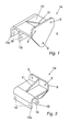
- a fixing is provided by a bracket 1a which has a back plate 5 with a flat rearward facing surface, through which holes 6 extend allowing the bracket 1a to be fixed to a wall W by means of screws or bolts etc.
- Extending at right angles from the plate 5 is an arm 10 having upper and lower braces 11 and 12 to resist flexing of the arm 10 relative to the plate 5.
- a U-shaped hook 15 is provided extending downwardly from the arm 10.
- the hook 15 has an outer limb 15o and an inner limb 15i which extend parallel to one another downwards from the arm 10.
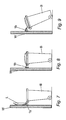
- the bracket 1a is typically formed of metal, but a plastics version of a similar bracket 1b is shown in Figs. 4 to 9, and has a back 5, arm 10, hook 15 and braces 11 and 12.
- the bracket 1 is mounted on a wall with the hook limbs 15o/15i facing downwards towards the ground.
- the bracket 1 is mounted at a height to receive between the hook legs 15o/15i a handle or bar of a wheeled refuse bin B.
- the handle H of the bin B is offered to the U-shaped hook 15 while the bin B is tilted as shown in Figs. 9 and 11.
- the base of the bin When the handle H is engaged between the limbs 15o/15i of the hook 15, the base of the bin is moved towards the wall W and the bin B pivots around the handle H until it is upright as shown in Figs. 7, 8 and 10. At that position, the handle H is restrained from outward movement away from the wall by the outer limb 15o of the hook, and is also restrained from moving towards the wall by the inner limb of the hook 15i. Therefore, the bin B is held securely in position and is wedged downwards against the ground G by the force of the bracket 1 pressing downwards. This restricts the bin's movements in the wind etc and prevents the bin from toppling over.
- the front of the bin B is simply lifted into the position shown in Fig. 11 or Fig. 9 so that the handle H can be disengaged from the hook 15 and the bin B removed from its position.
- the bracket has a degree of resilience that allows the hook 15 and arm 10 to flex up and down in order to accommodate the wedging action of the bin B as it is forced towards the wall W with the handle H between the limbs of the hook 15.
- the natural resilience of the plastic bin B or handle H can be used to prevent excessive stress on the bracket or on the fixing(s) securing it to the wall.
- the braces 11 and 12 can be built up or reduced in strength or size so as to permit or restrict the amount of flexing required.
- Typical embodiments of the invention can be made from plastics materials which incorporate a natural resilience or from appropriate metals that also have these properties.
- bracket 1 One advantage of certain embodiments of the bracket 1 is that the lid of the bin L can be opened while the bracket 1 is in place securing the bin B to the wall W.
- the brackets 1 can be mounted on the wall W as shown in the drawings or can be mounted the other way up with the limbs of the hook 15 directed upwards, and in that case the handle H can simply be hooked over the bracket to rest between the limbs 15i/15o of the hook 15 so as to secure the bin B to the wall W, without necessarily clamping it against the ground.
- a locking means can be provided to lock the bin or other container to the fixing or bracket.
- the bracket 1a, 1b can optionally have holes 16 in the limbs 15 to receive a padlock (not shown).
- the padlock can be secured through one or more of the holes 16 once the handle H of the bin B is in place between the limbs 15 of the bracket, preventing it from being withdrawn from the bracket 1a,1b, while the padlock is in place.
- the padlock does not need to be linked between two of the holes 16, but can be so linked if desired.
Landscapes
- Engineering & Computer Science (AREA)
- Mechanical Engineering (AREA)
- Binders And Loading Units For Sheaves (AREA)
- Refuse Receptacles (AREA)
Abstract
Description
Claims (10)
- A method of stabilising a container, the method comprising connecting the container to a support by means of a fixing having a hook, so that the hook on the fixing engages between a portion of the container and the support.
- A method as claimed in claim 1, further comprising the steps of moving the container into a first position in which it is misaligned with respect to the support, offering the container to the support in the first position, and moving the bin from the first position to a second position that is more aligned with the support, and in which the bin is clamped between the support and the surface on which it stands.
- A method as claimed in claim 1 or claim 2, wherein the container is a refuse container.
- A fixing for securing a container to a supporting, the fixing comprising a first portion adapted for attachment to the supporting structure, and a second portion for engaging a portion of the refuse bin, wherein the second portion comprises a hook.
- A fixing as claimed in claim 4, wherein the hook comprises an inverted U-shape.
- A fixing as claimed in claim 4 or claim 5, having a reinforcing protrusion to limit the amount of flexing of the hook.
- A fixing as claimed in claim 4, 5 or 6, wherein the fixing is integral with the container.
- A fixing as claimed in any one of claims 4-7, having a locking means to lock the container to the fixing.
- An assembly comprising a container secured to a support by means of a fixing comprising a hook, wherein the fixing is attached between the supporting structure and the container, and the container is clamped between the fixing and the ground.
- An assembly as claimed in claim 9, wherein the container is a wheeled refuse bin.
Applications Claiming Priority (2)
| Application Number | Priority Date | Filing Date | Title |
|---|---|---|---|
| GB0019195 | 2000-08-05 | ||
| GB0019195A GB0019195D0 (en) | 2000-08-05 | 2000-08-05 | Fixing |
Publications (2)
| Publication Number | Publication Date |
|---|---|
| EP1178224A2 true EP1178224A2 (en) | 2002-02-06 |
| EP1178224A3 EP1178224A3 (en) | 2003-04-16 |
Family
ID=9897007
Family Applications (1)
| Application Number | Title | Priority Date | Filing Date |
|---|---|---|---|
| EP01306578A Withdrawn EP1178224A3 (en) | 2000-08-05 | 2001-07-31 | Container mounting bracket |
Country Status (2)
| Country | Link |
|---|---|
| EP (1) | EP1178224A3 (en) |
| GB (1) | GB0019195D0 (en) |
Cited By (1)
| Publication number | Priority date | Publication date | Assignee | Title |
|---|---|---|---|---|
| WO2006032182A1 (en) * | 2004-09-24 | 2006-03-30 | China International Marine Containers(Group) Co., Ltd. | Pallet container |
Family Cites Families (5)
| Publication number | Priority date | Publication date | Assignee | Title |
|---|---|---|---|---|
| US3666223A (en) * | 1970-11-19 | 1972-05-30 | Arvel H Moore | Refuse container support |
| US4191297A (en) * | 1978-09-25 | 1980-03-04 | Hardman Olin A | Support and cover restraining device for refuse containers |
| GB2289083A (en) * | 1994-05-03 | 1995-11-08 | Harry Shann | A rubbish bin clamp having interlocking or hinged clamp plates |
| US5713499A (en) * | 1994-09-14 | 1998-02-03 | Daniel; John Thazhamana | Self detaching recycle bin and garbage drum attaching device |
| GB2342566A (en) * | 1998-09-14 | 2000-04-19 | Frederick Robert Mills | Securing device for the handle of a refuse container |
-
2000
- 2000-08-05 GB GB0019195A patent/GB0019195D0/en not_active Ceased
-
2001
- 2001-07-31 EP EP01306578A patent/EP1178224A3/en not_active Withdrawn
Cited By (1)
| Publication number | Priority date | Publication date | Assignee | Title |
|---|---|---|---|---|
| WO2006032182A1 (en) * | 2004-09-24 | 2006-03-30 | China International Marine Containers(Group) Co., Ltd. | Pallet container |
Also Published As
| Publication number | Publication date |
|---|---|
| GB0019195D0 (en) | 2000-09-27 |
| EP1178224A3 (en) | 2003-04-16 |
Similar Documents
| Publication | Publication Date | Title |
|---|---|---|
| US6148958A (en) | Ladder supported holding tray which extends outwardly from a ladder | |
| US2448456A (en) | Support for containers | |
| CA2465806C (en) | Vehicle hitch rack | |
| AU752848B1 (en) | Tailgate ramp and load locking accessories for a pickup truck | |
| US6877881B2 (en) | Worklight | |
| US5738261A (en) | Vehicle hitch for securing a hand truck, cart or other small load | |
| US20140145049A1 (en) | Tool holder | |
| US5213294A (en) | Locking support for refuse can | |
| WO2006055633A2 (en) | 23 gallon step-on receptacle with tip prevention | |
| US6382354B2 (en) | Ladder supported container | |
| US6173842B1 (en) | Multi-weeder rack for trucks/trailers | |
| MXPA00011474A (en) | Lift dolly for use with stand-mounted tools. | |
| US7527157B2 (en) | Wheel barrow rack and method of storing a wheel barrow | |
| CA2367676C (en) | Ladder levelling device | |
| US20170029208A1 (en) | Roll-out cart with lid latch | |
| US7874528B2 (en) | Lift and hold, anti-tipping trash container support system | |
| US7225933B1 (en) | Mounted storage device | |
| US7152835B1 (en) | Bracket assembly lock | |
| US9359134B1 (en) | Garbage can retaining device and method of use | |
| SE450713B (en) | SELF-LASING MANHALSLOCK | |
| WO1994029157A1 (en) | Additional sidepiece for a wheelbarrow | |
| US4184659A (en) | Receptacle support | |
| US20030052031A1 (en) | Storage system for detachable motorcycle windshield assemblies | |
| US4184660A (en) | Shelf and rod wall bracket | |
| US7849557B1 (en) | Backpack blower rack |
Legal Events
| Date | Code | Title | Description |
|---|---|---|---|
| PUAI | Public reference made under article 153(3) epc to a published international application that has entered the european phase |
Free format text: ORIGINAL CODE: 0009012 |
|
| AK | Designated contracting states |
Kind code of ref document: A2 Designated state(s): AT BE CH CY DE DK ES FI FR GB GR IE IT LI LU MC NL PT SE TR |
|
| AX | Request for extension of the european patent |
Free format text: AL;LT;LV;MK;RO;SI |
|
| PUAL | Search report despatched |
Free format text: ORIGINAL CODE: 0009013 |
|
| AK | Designated contracting states |
Designated state(s): AT BE CH CY DE DK ES FI FR GB GR IE IT LI LU MC NL PT SE TR |
|
| AX | Request for extension of the european patent |
Extension state: AL LT LV MK RO SI |
|
| RIC1 | Information provided on ipc code assigned before grant |
Ipc: 7F 16B 7/22 B Ipc: 7B 65F 1/14 B Ipc: 7B 65D 19/38 B Ipc: 7F 16B 7/04 A |
|
| 17P | Request for examination filed |
Effective date: 20031014 |
|
| AKX | Designation fees paid |
Designated state(s): AT BE CH CY DE DK ES FI FR GB GR IE IT LI LU MC NL PT SE TR |
|
| STAA | Information on the status of an ep patent application or granted ep patent |
Free format text: STATUS: THE APPLICATION IS DEEMED TO BE WITHDRAWN |
|
| 18D | Application deemed to be withdrawn |
Effective date: 20060201 |