EP1177982B1 - Label applicator head - Google Patents
Label applicator head Download PDFInfo
- Publication number
- EP1177982B1 EP1177982B1 EP01118486A EP01118486A EP1177982B1 EP 1177982 B1 EP1177982 B1 EP 1177982B1 EP 01118486 A EP01118486 A EP 01118486A EP 01118486 A EP01118486 A EP 01118486A EP 1177982 B1 EP1177982 B1 EP 1177982B1
- Authority
- EP
- European Patent Office
- Prior art keywords
- application
- motor
- labels
- goods
- head according
- Prior art date
- Legal status (The legal status is an assumption and is not a legal conclusion. Google has not performed a legal analysis and makes no representation as to the accuracy of the status listed.)
- Expired - Lifetime
Links
- 238000000034 method Methods 0.000 claims abstract description 9
- 238000002372 labelling Methods 0.000 abstract description 4
- 238000003825 pressing Methods 0.000 description 12
- 238000004519 manufacturing process Methods 0.000 description 2
- 239000000853 adhesive Substances 0.000 description 1
- 230000001070 adhesive effect Effects 0.000 description 1
- 239000012790 adhesive layer Substances 0.000 description 1
- 239000003795 chemical substances by application Substances 0.000 description 1
- 238000010586 diagram Methods 0.000 description 1
- 238000006073 displacement reaction Methods 0.000 description 1
- 238000004806 packaging method and process Methods 0.000 description 1
- 239000007787 solid Substances 0.000 description 1
- 239000000725 suspension Substances 0.000 description 1
Images

Classifications
-
- B—PERFORMING OPERATIONS; TRANSPORTING
- B65—CONVEYING; PACKING; STORING; HANDLING THIN OR FILAMENTARY MATERIAL
- B65C—LABELLING OR TAGGING MACHINES, APPARATUS, OR PROCESSES
- B65C9/00—Details of labelling machines or apparatus
- B65C9/26—Devices for applying labels
- B65C9/36—Wipers; Pressers
-
- B—PERFORMING OPERATIONS; TRANSPORTING
- B65—CONVEYING; PACKING; STORING; HANDLING THIN OR FILAMENTARY MATERIAL
- B65C—LABELLING OR TAGGING MACHINES, APPARATUS, OR PROCESSES
- B65C9/00—Details of labelling machines or apparatus
- B65C9/08—Label feeding
- B65C9/18—Label feeding from strips, e.g. from rolls
- B65C9/1865—Label feeding from strips, e.g. from rolls the labels adhering on a backing strip
- B65C9/1876—Label feeding from strips, e.g. from rolls the labels adhering on a backing strip and being transferred by suction means
- B65C9/1884—Label feeding from strips, e.g. from rolls the labels adhering on a backing strip and being transferred by suction means the suction means being a movable vacuum arm or pad
-
- Y—GENERAL TAGGING OF NEW TECHNOLOGICAL DEVELOPMENTS; GENERAL TAGGING OF CROSS-SECTIONAL TECHNOLOGIES SPANNING OVER SEVERAL SECTIONS OF THE IPC; TECHNICAL SUBJECTS COVERED BY FORMER USPC CROSS-REFERENCE ART COLLECTIONS [XRACs] AND DIGESTS
- Y10—TECHNICAL SUBJECTS COVERED BY FORMER USPC
- Y10T—TECHNICAL SUBJECTS COVERED BY FORMER US CLASSIFICATION
- Y10T156/00—Adhesive bonding and miscellaneous chemical manufacture
- Y10T156/17—Surface bonding means and/or assemblymeans with work feeding or handling means
- Y10T156/1702—For plural parts or plural areas of single part
- Y10T156/1744—Means bringing discrete articles into assembled relationship
- Y10T156/1746—Plural lines and/or separate means assembling separate sandwiches
-
- Y—GENERAL TAGGING OF NEW TECHNOLOGICAL DEVELOPMENTS; GENERAL TAGGING OF CROSS-SECTIONAL TECHNOLOGIES SPANNING OVER SEVERAL SECTIONS OF THE IPC; TECHNICAL SUBJECTS COVERED BY FORMER USPC CROSS-REFERENCE ART COLLECTIONS [XRACs] AND DIGESTS
- Y10—TECHNICAL SUBJECTS COVERED BY FORMER USPC
- Y10T—TECHNICAL SUBJECTS COVERED BY FORMER US CLASSIFICATION
- Y10T156/00—Adhesive bonding and miscellaneous chemical manufacture
- Y10T156/17—Surface bonding means and/or assemblymeans with work feeding or handling means
- Y10T156/1702—For plural parts or plural areas of single part
- Y10T156/1744—Means bringing discrete articles into assembled relationship
- Y10T156/1768—Means simultaneously conveying plural articles from a single source and serially presenting them to an assembly station
Definitions
- Such a box is known from EP 0 837 000 A.
- Packaged goods eg. As food, labels are nowadays provided. These labels are usually rolled from a dispenser over to Labeling goods placed and then pressed against these, so they firmly be liable.
- the currently available settling boxes have several drive units and are very elaborate and large in size.
- the drive means which is the means of transport and the means with which the contact pressure is shifted vertically, slip-free.
- This is particularly preferred Drive means a toothed belt or a chain.
- the means for vertical displacement of the pressing means can Pressing both lowered and raised.
- the Anpressstoff a Return spring on with the pressing means of a deflected end position in the starting position is pushed back.
- the contact pressure points in one preferred embodiment of a vertical guide. Preferably, this is Guide one or more ball sleeves.
- the transport means serves to place the labels over the label to be labeled Were.
- the means of transport must either have means by which the Stick labels on the transport or it must be an air flow and / or a Vacuum are generated, the / presses the labels against the transport and / or sucks.
- the transport is driven by a drive means.
- the means of transport is more Transport belts, which are 2 to 10 mm wide and essentially over the extend the entire width of the respective packaging machine.
- the transport belts have a distance of 2 to 10 mm.
- pressing means is any means by which the labels on the zu Labeling goods can be pressed, so that the adhesive layer, which is located under the labels, better comes into contact with the goods.
- the pressing means is a pressure plate, as described below.
- the means by which the pressing means is displaced vertically is in one preferred embodiment of a rotatable at one end about an axis Lever, a cam, which is driven by the drive means and the having a freewheel in a running direction of the drive means.
- a motor in particular a stepping motor is suitable, preferably is computer controlled.
- the settling box according to the invention has the advantage that it is simple and inexpensive is to produce and only has a drive unit. He is energy efficient and no compressed air is needed to press the labels. It only has one Aggregate be controlled by a controller.
- the pressing means is a pressure plate with a A plurality of punches which are displaceable relative to the pressure plate.
- the stamp are resilient, preferably stored in a sleeve.
- the Suspension can be done by screw or disc springs or by compressible Media, such as air done.
- Such a pressure plate has the advantage that bumps in the Contour of the goods to be labeled can be very well balanced.
- the Pressure plate is easy and inexpensive to manufacture.
- the inventive method has the advantage that it is simple and inexpensive and only one drive unit needed. It is energy efficient and no compressed air for pressing the labels must be provided. It only one unit must be controlled by a controller.
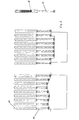
- FIG. 1 shows the settling box according to the invention.
- the goods to be packaged are moved in cycles, perpendicular to the paper level under the settling box according to the invention.
- the labels are released at the tear-off edge 11 of the label dispenser and transferred to the transport. Since there are usually several goods to be packed next to each other, several labels have to be handed over per cycle to the means of transport.
- the adhesive side of the labels is turned away from the conveyor belt.
- the transport means 2 are in this case a plurality of transport belts, which are arranged at such a distance from each other that the punch 10 of the pressure plate 3 between the conveyor belt 2 can be moved down through it to release the labels from the transport belt and to be packed on the Press on goods.
- the labels are pressed against the conveyor belts by a stream of air generated by a fan (not shown).
- the transport belts 2 are driven by the motor 5 via the toothed belt 6.
- the timing belt drives not only the transport belt, but also the drive means 4, a cam.
- the cam is rotatably mounted about the axis 12 and has a freewheel 14 in the direction of travel of the transport belt (label positioning). In the initial position, the cam 4 abuts against the stop 13.
- the running direction of the conveyor belt is shown by the arrow.
- the stamp solve the respective label from the transport belt and press against the goods to be labeled, so that a solid bond between label and goods is created.
- Figure 2 shows the mode of action of the stamp 10.
- a sleeve 15 is fixedly connected to a plate (not shown).
- a punch 10 is slidably installed in the sleeve.
- the punch is connected to the spring 16. Due to the resilient mounting of the stamp unevenness in the goods to be packaged can be compensated, so that the contact pressure is optimal everywhere.
- the pressure plate not only one, but preferably has a plurality of arranged in the paper plane successively rows of stamps.
Abstract
Description
Die vorliegende Erfindung betrifft einen Absetzkasten eines Etikettiergerätes mit:
- einem Transportmittel, mit dem die Etiketten über die zu etikettierenden Waren plaziert werden,
- einem vertikal verschiebbaren Anpressmittel, mit dem die Etiketten auf die zu etikettierenden Waren gedrückt werden,
- einem Mittel, mit dem das Anpressmittel vertikal verschoben wird,
- einem Motor mit Rechts- und Linkslauf und
- einem Antriebsmittel, das die Antriebsleistung des Motors auf das Mittel, mit dem das Anpressmittel vertikal verschoben wird, überträgt,
- a means of transport by which the labels are placed over the goods to be labeled,
- a vertically displaceable pressure means, with which the labels are pressed onto the goods to be labeled,
- a means by which the pressure medium is displaced vertically,
- a motor with clockwise and counterclockwise rotation and
- a drive means which transmits the drive power of the motor to the means by which the pressure means is displaced vertically,
Ein solchen Kasten ist aus EP 0 837 000 A bekannt. Verpackte Waren, z. B. Lebensmittel, werden heutzutage mit Etiketten versehen. Diese Etiketten werden in der Regel von einem Spender abgerollt, über den zu etikettierenden Waren plaziert und dann an diese angedrückt, so daß sie fest daran haften. Die derzeit verfügbaren Absetzkästen weisen mehrere Antriebsaggregate auf und sind sehr aufwendig und groß gestaltet.Such a box is known from EP 0 837 000 A. Packaged goods, eg. As food, labels are nowadays provided. These labels are usually rolled from a dispenser over to Labeling goods placed and then pressed against these, so they firmly be liable. The currently available settling boxes have several drive units and are very elaborate and large in size.
Es stellt sich deshalb die Aufgabe, einen Absetzkasten zur Verfügung zu stellen, der die Nachteile des Standes der Technik nicht aufweist und der einfach herzustellen ist.It is therefore the task to provide a settling box available, the does not have the disadvantages of the prior art and easy to manufacture is.
Die Aufgabe wird erfindungsgemäß durch einen Absetzkasten eines Etikettiergerätes mit:
- einem Transportmittel, mit dem die Etiketten über die zu etikettierenden Waren plaziert werden,
- einem vertikal verschiebbaren Anpressmittel, mit dem die Etiketten auf die zu etikettierenden Waren gedrückt werden,
- einem Mittel, mit dem das Anpressmittel vertikal verschoben wird,
- einem Motor mit Rechts- und Linkslauf und
- einem Antriebsmittel, das die Antriebsleistung des Motors auf das Mittel, mit dem das Anpressmittel vertikal verschoben wird, überträgt,
- a means of transport by which the labels are placed over the goods to be labeled,
- a vertically displaceable pressure means, with which the labels are pressed onto the goods to be labeled,
- a means by which the pressure medium is displaced vertically,
- a motor with clockwise and counterclockwise rotation and
- a drive means which transmits the drive power of the motor to the means by which the pressure means is displaced vertically,
Vorzugsweise ist das Antriebsmittel, das das Transportmittel und das Mittel, mit dem das Anpressmittel vertikal verschoben wird, schlupffrei. Besonders bevorzugt ist das Antriebsmittel ein Zahnriemen oder eine Kette.Preferably, the drive means, which is the means of transport and the means with which the contact pressure is shifted vertically, slip-free. This is particularly preferred Drive means a toothed belt or a chain.
Mit dem Mittel zur vertikalen Verschiebung des Anpressmittels kann das Anpressmittel sowohl abgesenkt als auch angehoben werden. In einer bevorzugten Ausführungsform der vorliegenden Erfindung weist das Anpressmittel jedoch eine Rückstellfeder auf, mit der das Anpressmittel von einer ausgelenkten Endstellung in die Ausgangsstellung zurückgedrückt wird. Das Anpressmittel weist in einer bevorzugten Ausführungsform eine vertikale Führung auf. Vorzugsweise ist diese Führung eine oder mehrere Kugelhülsen.With the means for vertical displacement of the pressing means can Pressing both lowered and raised. In a preferred Embodiment of the present invention, however, the Anpressmittel a Return spring on, with the pressing means of a deflected end position in the starting position is pushed back. The contact pressure points in one preferred embodiment of a vertical guide. Preferably, this is Guide one or more ball sleeves.
Das Transportmittel dient zur Plazierung der Etiketten über den zu etikettierenden Waren. Dafür muß das Transportmittel entweder Mittel aufweisen, durch die die Etiketten an dem Transportmittel haften oder es muß eine Luftströmung und/oder ein Unterdruck erzeugt werden, die/der die Etiketten gegen das Transportmittel drückt und/oder saugt. Das Transportmittel wird durch ein Antriebsmittel angetrieben. In einer bevorzugten Ausführungsform ist das Transportmittel mehrere Transportriemen, die 2 bis 10 mm breit sind und sich im wesentlichen über die gesamte Breite der jeweiligen Verpackungsmaschine erstrecken. Vorzugsweise haben die Transportriemen einen Abstand von 2 bis 10 mm.The transport means serves to place the labels over the label to be labeled Were. For this, the means of transport must either have means by which the Stick labels on the transport or it must be an air flow and / or a Vacuum are generated, the / presses the labels against the transport and / or sucks. The transport is driven by a drive means. In In a preferred embodiment, the means of transport is more Transport belts, which are 2 to 10 mm wide and essentially over the extend the entire width of the respective packaging machine. Preferably The transport belts have a distance of 2 to 10 mm.
Als Anpressmittel eignet sich jedes Mittel, mit dem die Etiketten auf die zu etikettierenden Waren gedrückt werden können, damit die Klebeschicht, die sich unter den Etiketten befindet, besser in Kontakt mit den Waren kommt. Vorzugsweise ist das Anpressmittel eine Anpressplatte, wie sie weiter unten beschrieben ist. As pressing means is any means by which the labels on the zu Labeling goods can be pressed, so that the adhesive layer, which is located under the labels, better comes into contact with the goods. Preferably the pressing means is a pressure plate, as described below.
Das Mittel, mit dem das Anpressmittel vertikal verschoben wird, ist in einer bevorzugten Ausführungsform ein an einem Ende um eine Achse drehbarer Hebelarm, eine Nocke, der/die durch das Antriebsmittel angetrieben wird und der einen Freilauf in eine Laufrichtung des Antriebsmittels aufweist.The means by which the pressing means is displaced vertically is in one preferred embodiment of a rotatable at one end about an axis Lever, a cam, which is driven by the drive means and the having a freewheel in a running direction of the drive means.
Als Motor ist insbesondere ein Schrittmotor geeignet, der vorzugsweise computergesteuert ist.As a motor, in particular a stepping motor is suitable, preferably is computer controlled.
Der erfindungsgemäße Absetzkasten hat den Vorteil, daß er einfach und günstig herzustellen ist und lediglich ein Antriebsaggregat aufweist. Er ist energieeffizient und es wird keine Druckluft zum Anpressen der Etiketten benötigt. Es muß lediglich ein Aggregat von einer Steuerung angesteuert werden.The settling box according to the invention has the advantage that it is simple and inexpensive is to produce and only has a drive unit. He is energy efficient and no compressed air is needed to press the labels. It only has one Aggregate be controlled by a controller.
Vorzugsweise ist das Anpressmittel eine Anpressplatte mit einer Mehrzahl von Stempeln, die relativ zu der Anpressplatte verschiebbar sind. Vorzugsweise sind die Stempel federnd, vorzugsweise in einer Hülse gelagert. Die Federung kann durch Schrauben- oder Tellerfedern oder durch kompressible Medien, beispielsweise Luft erfolgen.Preferably, the pressing means is a pressure plate with a A plurality of punches which are displaceable relative to the pressure plate. Preferably, the stamp are resilient, preferably stored in a sleeve. The Suspension can be done by screw or disc springs or by compressible Media, such as air done.
Eine solche Anpressplatte hat den Vorteil, daß Unebenheiten in der Kontur der zu etikettierenden Ware sehr gut ausgeglichen werden können. Die Anpressplatte ist einfach und günstig herzustellen.Such a pressure plate has the advantage that bumps in the Contour of the goods to be labeled can be very well balanced. The Pressure plate is easy and inexpensive to manufacture.
Ein weiterer Gegenstand der vorliegenden Erfindung ist ein Verfahren zur
Befestigung von Etiketten auf den zu etikettierenden Waren mit dem
erfindungsgemäßen Absetzkasten, das aus einer Abfolge der folgenden Schritte
besteht:
In einer bevorzugten Ausführungsform des erfindungsgemäßen Verfahrens wird das Transportmittel zwischen den Verfahrensschritten 1. und 2. und/oder 2. und 3. für 0 bis 1 Sekunde gestoppt.In a preferred embodiment of the method according to the invention is the Means of transport between method steps 1 and 2 and / or 2 and 3 for 0 stopped for 1 second.
Das erfindungsgemäße Verfahren hat den Vorteil, daß es einfach und günstig durchzuführen ist und lediglich ein Antriebsaggregat benötigt. Es ist energieeffizient und es muß keine Druckluft zum Anpressen der Etiketten bereitgestellt werden. Es muß lediglich ein Aggregat von einer Steuerung angesteuert werden.The inventive method has the advantage that it is simple and inexpensive and only one drive unit needed. It is energy efficient and no compressed air for pressing the labels must be provided. It only one unit must be controlled by a controller.
Im folgenden wird die Erfindung anhand der Figuren 1 und 2 erläutert. Diese Erläuterungen sind lediglich beispielhaft und schränken den allgemeinen Erfindungsgedanken nicht ein.
- Figur 1
- zeigt eine Prinzipskizze des erfindungsgemäßen Absetzkastens
- Figur 2
- zeigt die Funktionsweise der Stempel der Anpressplatte und eine bevorzugte Ausführungsform des Stempels
- FIG. 1
- shows a schematic diagram of the settling box according to the invention
- FIG. 2
- shows the operation of the punch of the pressure plate and a preferred embodiment of the punch
In Figur 1 ist der erfindungsgemäße Absetzkasten dargestellt. Die zu verpackenden
Waren werden taktweise, senkrecht zur Papierebene unter dem erfindungsgemäßen
Absetzkasten hindurch bewegt. Während des Etikettierens ist der Vorschub der
Waren gestoppt. Die Etiketten werden an der Abrißkante 11 von dem
Etikettenspender gelöst und an die Transportmittel übergeben. Da sich in der Regel
mehrere zu verpackende Waren nebeneinander befinden, müssen pro Takt mehrere
Etiketten an das Transportmittel übergeben werden. Die klebende Seite der Etiketten
ist von den Transportriemen abgewandt. Das Transportmittel 2 sind in diesem Fall
mehrere Transportriemen, die in einem solchen Abstand zueinander angeordnet
sind, daß die Stempel 10 der Anpressplatte 3 zwischen den Transportriemen 2
hindurch nach unten verschoben werden können, um die Etiketten von den
Transportriemen zu lösen und auf der zu verpackenden Ware anzudrücken. Die
Etiketten werden durch einen von einem Ventilator (nicht dargestellt) erzeugten
Luftstrom gegen die Transportriemen gedrückt. Die Transportriemen 2 werden über
den Zahnriemen 6 von dem Motor 5 angetrieben. Der Zahnriemen treibt nicht nur die
Transportriemen, sondern auch das Antriebsmittel 4, eine Nocke, an. Die Nocke ist
um die Achse 12 drehbar gelagert und weist einen Freilauf 14 in der Laufrichtung der
Transportriemen (Etikettenpositionierung) auf. In der Ausgangsstellung liegt die
Nocke 4 an dem Anschlag 13 an. Die Laufrichtung der Transportriemen ist durch den
Pfeil dargestellt. Bei dieser Laufrichtung überträgt der Zahnriemen 6 bedingt durch
den Freilauf 14 kein oder nur ein sehr kleines Drehmoment auf die Nocke 4. Sobald
die Etiketten ihre Position erreicht haben, wird die Laufrichtung des Motor 5
umgekehrt, so daß der Zahnriemen 6 nunmehr die Nocke 4 im Uhrzeigersinn nach
unten dreht und dabei die Anpressplatte 3 von der oberen Ausgangstellung 8 in die
untere Endstellung 9 verschiebt. Dabei lösen die Stempel die jeweilige Etikette von
den Transportriemen ab und drücken sie gegen die zu etikettierende Ware, so daß
ein fester Verbund zwischen Etikette und Ware entsteht. Sobald die Anpressplatte
ihre Endstellung erreicht hat, stoppt der Motor wieder und seine Drehrichtung wird
erneut umgedreht, so daß sich die Nocke 4 wieder gegen den Uhrzeigersinn nach
oben bis zum Anschlag 13 dreht. Sobald die Nocke 4 diese Stellung erreicht hat,
wirkt wiederum der Freilauf 14, so daß der Zahnriemen kein oder nur noch ein sehr
geringes Drehmoment auf die Nocke 4 ausübt. Gleichzeitig wird die Anpressplatte 3
durch die Federn 7 in die Ausgangsstellung zurückverschoben. Ebenfalls gleichzeitig
oder kurz danach beginnt der nächste Takt, so daß erneut Etiketten an die
Transportriemen übergeben und von diesen in ihre Position gebracht werden. Der
Fachmann erkennt, daß bei der Drehung der Nocke von der Ausgangs- in die
Endstellung, die Transportriemen und damit die Etiketten um einige Millimeter nach
links verschoben werden (Rücklauf Transportriemen). Diese Rückwärtsbewegung
kann jedoch entweder vernachlässigt oder durch die Computersteuerung des Motors
bei der Positionierung der Etiketten berücksichtigt und damit kompensiert werden. FIG. 1 shows the settling box according to the invention. The goods to be packaged are moved in cycles, perpendicular to the paper level under the settling box according to the invention. During labeling, the feed of the goods is stopped. The labels are released at the tear-
Figur 2 zeigt die Wirkweise der Stempel 10. Eine Hülse 15 ist fest mit einer Platte
(nicht dargestellt) verbunden. In der Hülse ist verschiebbar ein Stempel 10 eingebaut.
Der Stempel ist mit der Feder 16 verbunden. Durch die federnde Lagerung der
Stempel können Unebenheiten bei der zu verpackenden Ware ausgeglichen werden,
so daß der Anpressdruck überall optimal ist. Der Fachmann erkennt, daß die
Anpressplatte nicht nur eine, sondern vorzugsweise mehrere in
der Papierebene hintereinander angeordnete Stempelreihen aufweist. Figure 2 shows the mode of action of the
Claims (11)
- Head (1) of a label applicator with:a conveyor (2) with which the labels are placed over the goods to be labelled,a vertical movable means of application (3) with which the labels are pressed onto the goods to be labelled,a means (4) with which the means of application (3) is moved vertically,a motor (5) with clockwise and anti-clockwise rotation anda driving means (6), which transmits the driving power of the motor to the means (4), characterised in that the driving means (6) transfers the driving power of the motor (5) to the conveyor (2), and in that the means (4), with which the means of application is moved vertically, has a free-wheel (14) in one direction of rotation of the motor.
- Head according to claim 1, characterised in that the driving means (6) is a toothed belt or a chain.
- Head according to claim 1 or 2, characterised in that there is a return spring (7) on the means of application (3).
- Head according to one of the claims 1 to 3, characterised in that the conveyor (2) is made up of several conveyor belts, which are arranged so that there is a space of 2-10 cm between them.
- Head according to claims 1 to 4, characterised in that the means of application (3) has a vertical guide.
- Head according to one of the claims 1 to 5, characterised in that the means (4) is a cam.
- Head according to one of the claims 1 to 6, characterised in that the means of application (3) consists of an application plate to which is attached several stamps (10), which can be moved in relation to this application plate.
- Head according to claim 7, characterised in that the stamps (10) are spring mounted.
- Head according to one of the claims 1 to 8, characterised in that the motor is preferably a computer controlled step motor.
- Procedure for attaching labels to goods to be labelled using a head according to one of the claims 1 to 9, characterised in that it is made up of a sequence of the following steps:1. Positioning the labels over the goods to be labelled using the conveyor (2) driven by the motor (5),2. Reversal of the running direction of the driving means (6) until the means (4) has moved the means of application (3) from its upper starting position (8) into its lower final position (9) and while simultaneously applying the labels to the goods to be labelled and3. again reversal of the running direction of the driving means (6) in order to return the means (4), with which the means of application is moved vertically, and hence the means of application (3) to its starting position (8).
- Procedure according to claim 10, characterised in that the conveyor (2) is stopped for a short time between the first and second steps of the procedure and /or between the second and third steps of the procedure.
Applications Claiming Priority (2)
| Application Number | Priority Date | Filing Date | Title |
|---|---|---|---|
| DE10037864A DE10037864A1 (en) | 2000-08-01 | 2000-08-01 | Absetzkasten |
| DE10037864 | 2000-08-01 |
Publications (2)
| Publication Number | Publication Date |
|---|---|
| EP1177982A1 EP1177982A1 (en) | 2002-02-06 |
| EP1177982B1 true EP1177982B1 (en) | 2003-12-10 |
Family
ID=7651209
Family Applications (1)
| Application Number | Title | Priority Date | Filing Date |
|---|---|---|---|
| EP01118486A Expired - Lifetime EP1177982B1 (en) | 2000-08-01 | 2001-08-01 | Label applicator head |
Country Status (6)
| Country | Link |
|---|---|
| US (2) | US6634404B2 (en) |
| EP (1) | EP1177982B1 (en) |
| AT (1) | ATE256039T1 (en) |
| DE (2) | DE10037864A1 (en) |
| DK (1) | DK1177982T3 (en) |
| ES (1) | ES2214366T3 (en) |
Families Citing this family (8)
| Publication number | Priority date | Publication date | Assignee | Title |
|---|---|---|---|---|
| US20030056894A1 (en) * | 2001-09-25 | 2003-03-27 | John Getz | Applicator for adhesively-impregnated tape |
| US20060157202A1 (en) * | 2003-06-05 | 2006-07-20 | Arippol Giuseppe J | System to bring adhesive backed articles into assembled association with products |
| US6868887B2 (en) * | 2003-06-12 | 2005-03-22 | Koch Equipment Llc | Labeling device having enhanced sanitary design |
| US7318877B2 (en) * | 2005-11-23 | 2008-01-15 | Koch Equipment Llc | High speed labeling device and method |
| EP2666728B1 (en) | 2012-05-22 | 2016-12-07 | MULTIVAC Marking & Inspection GmbH & Co. KG | Labelling device and labelling method |
| ES2566364T3 (en) | 2012-09-28 | 2016-04-12 | Kronoplus Technical Ag | Apparatus and procedure for applying labels to boxes |
| DK3495280T3 (en) * | 2017-12-08 | 2021-07-05 | Multivac Marking & Inspection | Labeling machine with slider unit |
| DE102021105699A1 (en) | 2021-03-09 | 2022-09-15 | Multivac Marking & Inspection Gmbh & Co. Kg | Labeller with pusher assembly |
Family Cites Families (17)
| Publication number | Priority date | Publication date | Assignee | Title |
|---|---|---|---|---|
| US3340719A (en) * | 1964-10-28 | 1967-09-12 | Strick Corp | Apparatus and method of producing multiple corrugations simultaneously |
| US3420172A (en) | 1967-10-09 | 1969-01-07 | Label Matic Inc | Apparatus for feeding and attaching labels |
| US4046613A (en) * | 1976-03-08 | 1977-09-06 | Label-Aire Inc. | Matrix label applicator |
| DE7717056U1 (en) | 1977-05-28 | 1977-09-08 | Kronseder, Hermann, 8404 Woerth | DEVICE FOR PRESSING LABELS |
| DE3019506C2 (en) * | 1980-05-22 | 1983-12-22 | Max H. 4901 Hiddenhausen Klinger | Labeling device |
| US4397709A (en) * | 1982-08-26 | 1983-08-09 | Njm, Inc. | Labeling machine |
| US4557783A (en) * | 1983-12-05 | 1985-12-10 | Cincinnati Milacron Inc. | Composite tape laying machine and method |
| DE8706948U1 (en) | 1987-05-14 | 1987-07-02 | Klinger, Max H., 4901 Hiddenhausen, De | |
| US5281296A (en) * | 1991-07-30 | 1994-01-25 | Markem Corporation | Label applicator |
| US5300181A (en) * | 1991-10-09 | 1994-04-05 | Osaka Sealing Printing Co., Ltd. | Label sticking apparatus |
| IT1253216B (en) * | 1991-10-21 | 1995-07-11 | Gd Spa | DEVICE FOR THE APPLICATION OF ADHESIVE BANDS TO PACKAGES |
| DE4344787C2 (en) * | 1992-12-28 | 2001-06-07 | Fuji Photo Film Co Ltd | Sheet metal bending process and sheet bending device for two-stage bending of a thin metal plate |
| GB9604568D0 (en) * | 1996-03-04 | 1996-05-01 | Markem Syst Ltd | Label applicator |
| US5824183A (en) * | 1996-04-03 | 1998-10-20 | Crankshaw; Michael | High speed corner labeler |
| IT1284967B1 (en) * | 1996-10-16 | 1998-05-28 | Francesco Lupoli | LABEL APPLICATOR DEVICE |
| JP2000294172A (en) * | 1999-04-12 | 2000-10-20 | Kyoritsu Kogyo Kk | Sheet material affixing device |
| JP3725377B2 (en) * | 1999-10-01 | 2005-12-07 | アイダエンジニアリング株式会社 | Double acting hydraulic press |
-
2000
- 2000-08-01 DE DE10037864A patent/DE10037864A1/en not_active Withdrawn
-
2001
- 2001-08-01 EP EP01118486A patent/EP1177982B1/en not_active Expired - Lifetime
- 2001-08-01 DE DE50101116T patent/DE50101116D1/en not_active Expired - Lifetime
- 2001-08-01 US US09/920,031 patent/US6634404B2/en not_active Expired - Lifetime
- 2001-08-01 ES ES01118486T patent/ES2214366T3/en not_active Expired - Lifetime
- 2001-08-01 DK DK01118486T patent/DK1177982T3/en active
- 2001-08-01 AT AT01118486T patent/ATE256039T1/en not_active IP Right Cessation
-
2003
- 2003-06-24 US US10/604,064 patent/US20030234084A1/en not_active Abandoned
Also Published As
| Publication number | Publication date |
|---|---|
| DK1177982T3 (en) | 2004-04-13 |
| EP1177982A1 (en) | 2002-02-06 |
| DE50101116D1 (en) | 2004-01-22 |
| ES2214366T3 (en) | 2004-09-16 |
| US6634404B2 (en) | 2003-10-21 |
| US20020043345A1 (en) | 2002-04-18 |
| DE10037864A1 (en) | 2002-03-07 |
| ATE256039T1 (en) | 2003-12-15 |
| US20030234084A1 (en) | 2003-12-25 |
Similar Documents
| Publication | Publication Date | Title |
|---|---|---|
| DE60022093T2 (en) | CONTINUOUS WORKING DEVICE IN A FACILITY THAT MAKES GROUPS OF OBJECTS SHIPMENTS | |
| EP1177982B1 (en) | Label applicator head | |
| DE2716743A1 (en) | PRINTING DEVICE | |
| DD297378A5 (en) | METHOD AND ESTABLISHMENT FOR THE APPOINTMENT OF STUDENTS OF OPENING | |
| DE1586396A1 (en) | Automatic cradle and label printing machine | |
| CH660163A5 (en) | PACKING DEVICE. | |
| DE1936371C3 (en) | Device for conveying away finished stacks of printed matter | |
| DE2526529A1 (en) | SCREW HOLDER LOADING DEVICE | |
| DE3526711C2 (en) | ||
| DE3219770A1 (en) | METHOD AND DEVICE FOR LAMINATING SHEET MATERIALS | |
| DE2721507A1 (en) | METHOD AND DEVICE FOR EATING A PACK | |
| DE2528929C2 (en) | Labeling device, in particular for boxes | |
| DE2719957C3 (en) | Labeling device | |
| DE4209141A1 (en) | Packaging carton erection machine from blank - has prefolding die set above mouth of blank magazine, with pref. two folders in front of main folding die | |
| DE623478C (en) | ||
| DE1284891B (en) | Labeling machine | |
| DE3534919A1 (en) | BAGS OF STACKING AND INTERMITTENTLY MOVING CONVEYORS | |
| DE3245154A1 (en) | DEVICE FOR PROMOTING LABELS | |
| DE473328C (en) | Sample cutting and gluing machine | |
| CH663193A5 (en) | MACHINE FOR FEEDING PRINTED GOODS. | |
| DE2429292C3 (en) | Semi-automatic labeling device | |
| CH432339A (en) | Device for manufacturing, filling and closing packages | |
| EP0216989B1 (en) | Device for pulling a pile of thermoplastic bags from under a pile being formed | |
| DE845923C (en) | Method and device for locally limited surface treatment of objects conveyed on a belt | |
| DE1436050C (en) | Labeling device |
Legal Events
| Date | Code | Title | Description |
|---|---|---|---|
| PUAI | Public reference made under article 153(3) epc to a published international application that has entered the european phase |
Free format text: ORIGINAL CODE: 0009012 |
|
| AK | Designated contracting states |
Kind code of ref document: A1 Designated state(s): AT BE CH CY DE DK ES FI FR GB GR IE IT LI LU MC NL PT SE TR |
|
| AX | Request for extension of the european patent |
Free format text: AL;LT;LV;MK;RO;SI |
|
| 17P | Request for examination filed |
Effective date: 20020806 |
|
| AKX | Designation fees paid |
Free format text: AT BE CH CY DE DK ES FI FR GB GR IE IT LI LU MC NL PT SE TR |
|
| GRAH | Despatch of communication of intention to grant a patent |
Free format text: ORIGINAL CODE: EPIDOS IGRA |
|
| GRAS | Grant fee paid |
Free format text: ORIGINAL CODE: EPIDOSNIGR3 |
|
| GRAA | (expected) grant |
Free format text: ORIGINAL CODE: 0009210 |
|
| AK | Designated contracting states |
Kind code of ref document: B1 Designated state(s): AT BE CH CY DE DK ES FI FR GB GR IE IT LI LU MC NL PT SE TR |
|
| PG25 | Lapsed in a contracting state [announced via postgrant information from national office to epo] |
Ref country code: TR Free format text: LAPSE BECAUSE OF FAILURE TO SUBMIT A TRANSLATION OF THE DESCRIPTION OR TO PAY THE FEE WITHIN THE PRESCRIBED TIME-LIMIT Effective date: 20031210 Ref country code: CY Free format text: LAPSE BECAUSE OF FAILURE TO SUBMIT A TRANSLATION OF THE DESCRIPTION OR TO PAY THE FEE WITHIN THE PRESCRIBED TIME-LIMIT Effective date: 20031210 Ref country code: IE Free format text: LAPSE BECAUSE OF FAILURE TO SUBMIT A TRANSLATION OF THE DESCRIPTION OR TO PAY THE FEE WITHIN THE PRESCRIBED TIME-LIMIT Effective date: 20031210 |
|
| REG | Reference to a national code |
Ref country code: GB Ref legal event code: FG4D Free format text: NOT ENGLISH |
|
| REG | Reference to a national code |
Ref country code: CH Ref legal event code: EP |
|
| REG | Reference to a national code |
Ref country code: IE Ref legal event code: FG4D Free format text: GERMAN |
|
| REF | Corresponds to: |
Ref document number: 50101116 Country of ref document: DE Date of ref document: 20040122 Kind code of ref document: P |
|
| PG25 | Lapsed in a contracting state [announced via postgrant information from national office to epo] |
Ref country code: GR Free format text: LAPSE BECAUSE OF FAILURE TO SUBMIT A TRANSLATION OF THE DESCRIPTION OR TO PAY THE FEE WITHIN THE PRESCRIBED TIME-LIMIT Effective date: 20040310 |
|
| REG | Reference to a national code |
Ref country code: SE Ref legal event code: TRGR |
|
| GBT | Gb: translation of ep patent filed (gb section 77(6)(a)/1977) |
Effective date: 20040315 |
|
| REG | Reference to a national code |
Ref country code: DK Ref legal event code: T3 |
|
| REG | Reference to a national code |
Ref country code: IE Ref legal event code: FD4D |
|
| PG25 | Lapsed in a contracting state [announced via postgrant information from national office to epo] |
Ref country code: LU Free format text: LAPSE BECAUSE OF NON-PAYMENT OF DUE FEES Effective date: 20040801 |
|
| PG25 | Lapsed in a contracting state [announced via postgrant information from national office to epo] |
Ref country code: MC Free format text: LAPSE BECAUSE OF NON-PAYMENT OF DUE FEES Effective date: 20040831 |
|
| REG | Reference to a national code |
Ref country code: ES Ref legal event code: FG2A Ref document number: 2214366 Country of ref document: ES Kind code of ref document: T3 |
|
| ET | Fr: translation filed | ||
| PLBE | No opposition filed within time limit |
Free format text: ORIGINAL CODE: 0009261 |
|
| STAA | Information on the status of an ep patent application or granted ep patent |
Free format text: STATUS: NO OPPOSITION FILED WITHIN TIME LIMIT |
|
| 26N | No opposition filed |
Effective date: 20040913 |
|
| REG | Reference to a national code |
Ref country code: DK Ref legal event code: EBP |
|
| REG | Reference to a national code |
Ref country code: DK Ref legal event code: EGE |
|
| PGFP | Annual fee paid to national office [announced via postgrant information from national office to epo] |
Ref country code: ES Payment date: 20070925 Year of fee payment: 7 |
|
| PGFP | Annual fee paid to national office [announced via postgrant information from national office to epo] |
Ref country code: AT Payment date: 20070926 Year of fee payment: 7 Ref country code: CH Payment date: 20070924 Year of fee payment: 7 |
|
| PG25 | Lapsed in a contracting state [announced via postgrant information from national office to epo] |
Ref country code: PT Free format text: LAPSE BECAUSE OF NON-PAYMENT OF DUE FEES Effective date: 20040510 |
|
| PGFP | Annual fee paid to national office [announced via postgrant information from national office to epo] |
Ref country code: BE Payment date: 20070921 Year of fee payment: 7 Ref country code: SE Payment date: 20070924 Year of fee payment: 7 |
|
| REG | Reference to a national code |
Ref country code: CH Ref legal event code: PL |
|
| EUG | Se: european patent has lapsed | ||
| PG25 | Lapsed in a contracting state [announced via postgrant information from national office to epo] |
Ref country code: AT Free format text: LAPSE BECAUSE OF NON-PAYMENT OF DUE FEES Effective date: 20080801 |
|
| PG25 | Lapsed in a contracting state [announced via postgrant information from national office to epo] |
Ref country code: LI Free format text: LAPSE BECAUSE OF NON-PAYMENT OF DUE FEES Effective date: 20080831 Ref country code: CH Free format text: LAPSE BECAUSE OF NON-PAYMENT OF DUE FEES Effective date: 20080831 |
|
| PG25 | Lapsed in a contracting state [announced via postgrant information from national office to epo] |
Ref country code: BE Free format text: LAPSE BECAUSE OF NON-PAYMENT OF DUE FEES Effective date: 20080831 |
|
| REG | Reference to a national code |
Ref country code: ES Ref legal event code: FD2A Effective date: 20080802 |
|
| PG25 | Lapsed in a contracting state [announced via postgrant information from national office to epo] |
Ref country code: ES Free format text: LAPSE BECAUSE OF NON-PAYMENT OF DUE FEES Effective date: 20080802 |
|
| PG25 | Lapsed in a contracting state [announced via postgrant information from national office to epo] |
Ref country code: SE Free format text: LAPSE BECAUSE OF NON-PAYMENT OF DUE FEES Effective date: 20080802 |
|
| REG | Reference to a national code |
Ref country code: FR Ref legal event code: PLFP Year of fee payment: 16 |
|
| PGFP | Annual fee paid to national office [announced via postgrant information from national office to epo] |
Ref country code: FI Payment date: 20160921 Year of fee payment: 16 Ref country code: DK Payment date: 20160923 Year of fee payment: 16 |
|
| REG | Reference to a national code |
Ref country code: FR Ref legal event code: PLFP Year of fee payment: 17 |
|
| REG | Reference to a national code |
Ref country code: DK Ref legal event code: EBP Effective date: 20040831 Ref country code: DK Ref legal event code: EBP Effective date: 20170831 |
|
| PG25 | Lapsed in a contracting state [announced via postgrant information from national office to epo] |
Ref country code: FI Free format text: LAPSE BECAUSE OF NON-PAYMENT OF DUE FEES Effective date: 20170801 |
|
| PG25 | Lapsed in a contracting state [announced via postgrant information from national office to epo] |
Ref country code: DK Free format text: LAPSE BECAUSE OF NON-PAYMENT OF DUE FEES Effective date: 20170831 |
|
| REG | Reference to a national code |
Ref country code: FR Ref legal event code: PLFP Year of fee payment: 18 |
|
| PGFP | Annual fee paid to national office [announced via postgrant information from national office to epo] |
Ref country code: NL Payment date: 20200819 Year of fee payment: 20 |
|
| PGFP | Annual fee paid to national office [announced via postgrant information from national office to epo] |
Ref country code: DE Payment date: 20200819 Year of fee payment: 20 Ref country code: FR Payment date: 20200819 Year of fee payment: 20 Ref country code: GB Payment date: 20200824 Year of fee payment: 20 |
|
| PGFP | Annual fee paid to national office [announced via postgrant information from national office to epo] |
Ref country code: IT Payment date: 20200831 Year of fee payment: 20 |
|
| REG | Reference to a national code |
Ref country code: DE Ref legal event code: R071 Ref document number: 50101116 Country of ref document: DE |
|
| REG | Reference to a national code |
Ref country code: NL Ref legal event code: MK Effective date: 20210731 |
|
| REG | Reference to a national code |
Ref country code: GB Ref legal event code: PE20 Expiry date: 20210731 |
|
| PG25 | Lapsed in a contracting state [announced via postgrant information from national office to epo] |
Ref country code: GB Free format text: LAPSE BECAUSE OF EXPIRATION OF PROTECTION Effective date: 20210731 |