EP1177967A1 - Hydraulic power steering system with a pressure relief valve - Google Patents
Hydraulic power steering system with a pressure relief valve Download PDFInfo
- Publication number
- EP1177967A1 EP1177967A1 EP01114493A EP01114493A EP1177967A1 EP 1177967 A1 EP1177967 A1 EP 1177967A1 EP 01114493 A EP01114493 A EP 01114493A EP 01114493 A EP01114493 A EP 01114493A EP 1177967 A1 EP1177967 A1 EP 1177967A1
- Authority
- EP
- European Patent Office
- Prior art keywords
- pressure relief
- relief valve
- valve
- steering gear
- hydraulic power
- Prior art date
- Legal status (The legal status is an assumption and is not a legal conclusion. Google has not performed a legal analysis and makes no representation as to the accuracy of the status listed.)
- Granted
Links
Images


Classifications
-
- B—PERFORMING OPERATIONS; TRANSPORTING
- B62—LAND VEHICLES FOR TRAVELLING OTHERWISE THAN ON RAILS
- B62D—MOTOR VEHICLES; TRAILERS
- B62D5/00—Power-assisted or power-driven steering
- B62D5/06—Power-assisted or power-driven steering fluid, i.e. using a pressurised fluid for most or all the force required for steering a vehicle
- B62D5/062—Details, component parts
-
- Y—GENERAL TAGGING OF NEW TECHNOLOGICAL DEVELOPMENTS; GENERAL TAGGING OF CROSS-SECTIONAL TECHNOLOGIES SPANNING OVER SEVERAL SECTIONS OF THE IPC; TECHNICAL SUBJECTS COVERED BY FORMER USPC CROSS-REFERENCE ART COLLECTIONS [XRACs] AND DIGESTS
- Y10—TECHNICAL SUBJECTS COVERED BY FORMER USPC
- Y10T—TECHNICAL SUBJECTS COVERED BY FORMER US CLASSIFICATION
- Y10T137/00—Fluid handling
- Y10T137/7722—Line condition change responsive valves
- Y10T137/7837—Direct response valves [i.e., check valve type]
- Y10T137/7838—Plural
- Y10T137/7845—With common biasing means
-
- Y—GENERAL TAGGING OF NEW TECHNOLOGICAL DEVELOPMENTS; GENERAL TAGGING OF CROSS-SECTIONAL TECHNOLOGIES SPANNING OVER SEVERAL SECTIONS OF THE IPC; TECHNICAL SUBJECTS COVERED BY FORMER USPC CROSS-REFERENCE ART COLLECTIONS [XRACs] AND DIGESTS
- Y10—TECHNICAL SUBJECTS COVERED BY FORMER USPC
- Y10T—TECHNICAL SUBJECTS COVERED BY FORMER US CLASSIFICATION
- Y10T137/00—Fluid handling
- Y10T137/7722—Line condition change responsive valves
- Y10T137/7837—Direct response valves [i.e., check valve type]
- Y10T137/7838—Plural
- Y10T137/7846—Mechanically interconnected
-
- Y—GENERAL TAGGING OF NEW TECHNOLOGICAL DEVELOPMENTS; GENERAL TAGGING OF CROSS-SECTIONAL TECHNOLOGIES SPANNING OVER SEVERAL SECTIONS OF THE IPC; TECHNICAL SUBJECTS COVERED BY FORMER USPC CROSS-REFERENCE ART COLLECTIONS [XRACs] AND DIGESTS
- Y10—TECHNICAL SUBJECTS COVERED BY FORMER USPC
- Y10T—TECHNICAL SUBJECTS COVERED BY FORMER US CLASSIFICATION
- Y10T137/00—Fluid handling
- Y10T137/7722—Line condition change responsive valves
- Y10T137/7837—Direct response valves [i.e., check valve type]
- Y10T137/7866—Plural seating
Definitions
- the present invention relates to a hydraulic power steering system for turning steerable wheels of a vehicle.
- a known power steering gear for turning steerable wheels of a vehicle is hydraulically operated.
- the power steering gear is associated with a pump that may be powered by the vehicle engine.
- the power steering gear to aid the vehicle driver in turning the steerable wheels of the vehicle, utilizes pressurized hydraulic fluid from the pump.
- the power steering gear includes a hydraulic motor and a steering valve for controlling fluid flow to the hydraulic motor.
- the hydraulic motor includes two chamber portions that are separated by an axially movable piston. A fluid pressure difference in the respective chamber portions causes the piston to move axially resulting in movement of the steerable wheels of the vehicle. Resistance to movement of the steerable wheels results in an increased pressure in the inlet of the steering gear. This increased pressure may result in some instability in the vehicle steering and some audible noise.
- the present invention is a hydraulic power steering system for turning steerable wheels of a vehicle.
- the system comprises a steering gear that includes a hydraulic motor and a steering valve for controlling actuation of the hydraulic motor by controlling fluid flow to the hydraulic motor.
- the hydraulic motor when actuated turns steerable vehicle wheels.
- the steering gear has an inlet, in communication with a fluid source, and an outlet for directing the fluid from the steering gear to a reservoir.
- the steering gear is susceptible to pressure fluctuations that may cause noise during steering.
- the system further comprises a pressure relief valve having an unactuated condition and actuated conditions.
- the pressure relief valve in the unactuated condition, restricts fluid flow through the pressure relief valve. In an actuated condition, the pressure relief valve permits fluid flow through the pressure relief valve.
- the pressure relief valve progressively moves from the unactuated condition to an actuated condition as a pressure differential between the inlet and the outlet of the steering gear increases.
- the pressure relief valve when in an actuated condition, provides fluid communication between the inlet and the outlet of the steering gear to minimize pressure fluctuations in the steering gear.
- Fig. 1 is a schematic illustration of a hydraulic power steering system 10 embodying the present invention.
- the system 10 includes a hydraulic steering gear 12 and a pressure relief valve 14.
- the steering gear 12 and the pressure relief valve 14 are in parallel connection to one another in the system 10.
- Both the steering gear 12 and the pressure relief valve 14 receive fluid from a pump 16 that is connected to a fluid reservoir 18.
- a feed line 86 extends from the reservoir 18 to the inlet of the pump 16.
- the outlet of the pump 16 is in fluid communication with a conduit 88.
- Conduit 88 communicates with conduits 90 and 92 for directing fluid to the steering gear 12 and the pressure relief valve 14, respectively.
- the conduit 90 communicates with an inlet 38 of the steering gear 12, and conduit 92 communicates with an inlet 50 of the pressure relief valve 14.
- Conduit 94 is in fluid communication with outlets 40 and 52 of the steering gear 12 and the pressure relief valve 14, respectively.
- a first conduit 96 and a second conduit 98 extend from the outlets 40 and 52 of the steering gear 12 and the pressure relief valve 14, respectively, and communicate with the conduit 94.
- Conduit 94 communicates with the reservoir 18.
- Fig. 2 illustrates the steering gear 12 of the system 10.
- the steering gear 12 of Fig. 2 is for illustrative purposes only.
- the system 10 of the present invention may incorporate any suitable hydraulic steering gear.
- the steering gear 12 has a housing 20 with an inner cylindrical surface 22 defining a chamber.
- a piston 24 is located within the chamber and divides the chamber into opposite chamber portions 26 and 28.
- One chamber portion 26 or 28 is located on each end of the piston 24.
- the piston 24 creates a seal between the respective chamber portions 26 and 28 and is capable of axial motion within the chamber. This axial motion of the piston 24 is caused by a pressure differential across the piston (between chamber portions 26 and 28). As the piston 24 moves axially an increase in volume of one portion of the chamber 26 or 28 and a corresponding decrease in the volume of the other portion of the chamber 26 or 28 occurs.
- a series of rack teeth 30 is formed on the periphery of the piston 24.
- the rack teeth 30 mesh with the teeth 32 formed on a sector gear 34.
- the sector gear 34 is fixed on an output shaft 36 that extends outwardly through an opening (not shown) in the housing 20.
- the output shaft 36 is typically connected to a pitman arm (not shown) that is connected to the steering linkage (not shown) of the vehicle.
- the sector gear 34 rotates, the output shaft 36 is rotated to operate the steering linkage. As a result, the steerable wheels are turned.
- the housing 20 of the steering gear 12 includes the inlet 38 and the outlet 40.
- the inlet 38 is in fluid communication with the pump 16 and is in fluid communication with a directional control valve 42 of the steering gear 12.
- the directional control valve 42 is also known as a steering valve.
- the directional control valve 42 includes relatively rotatable valve members 42a, 42b.
- Valve member 42a rotates in response to rotation of the steering wheel of the vehicle.
- Valve member 42b rotates in a follow-up manner as is known.
- the valve members 42a, 42b direct the flow of hydraulic fluid to one of the chamber portions 26 or 28.
- the flow of hydraulic fluid to one of the chamber portions 26 or 28 increases the pressure within that chamber portion 26 or 28 and causes the piston 24 to move axially.
- the piston 24 moves axially until the pressure within the chamber portions 26 and 28 equalizes or until the piston moves to a limit.
- the valve member 42b rotates due to axial movement of the piston 24 that causes rotation of screw 42c, which is connected to and rotates valve member 42b.
- Hydraulic fluid flows from the chamber portion that is decreasing in volume to the directional control valve 42. This fluid exits from the directional control valve 42 and the housing 20 of the steering gear 12 through the outlet 40.
- Fig. 3 illustrates an embodiment of the pressure relief valve 14 of the system 10.
- the system 10 may incorporate a pressure relief valve of a different construction.
- the pressure relief valve 14 includes a valve body 44, a valve plug 46, and a valve stem assembly 48.
- the valve body 44 is a hollow, cylindrical body formed of an outer cylindrical surface 45 and an inner cylindrical surface 47.
- a cylindrical valve chamber 54 is defined by the inner cylindrical surface 47.
- the valve body 44 includes three openings.
- a first opening is threaded to receive the valve plug 46.
- the first opening is located on a first end 53 of the cylindrical valve body 44 and is defined by the inner cylindrical surface 47 of the valve body 44.
- the second and third openings form the valve inlet 50 and the valve outlet 52, respectively.
- the valve inlet 50 is an opening that extends through the cylindrical surfaces 45 and 47 of the valve body 44 and allows fluid flow into a cylindrical valve chamber 54.
- the valve outlet 52 is located on a second end 58 of the valve body 44 and allows fluid flow out of the chamber 54.
- a ledge 56 extends radially inwardly from the inner cylindrical surface 47 into the cylindrical valve chamber 54 at the second end 58 of the valve body 44 near the valve outlet 52.
- the ledge 56 extends axially approximately 20% of the length of the chamber 54.
- the ledge 56 has an axially extending, cylindrical ledge surface 57 and a radially extending, annular ledge surface 59.
- the diameter of the chamber 54 is reduced in the area containing the ledge 56 by 25% to 40%.
- the diameter of the valve outlet 52 is approximately 50% of the diameter of the chamber 54 in the area of the ledge 56.
- a groove 60 is located on the outer cylindrical surface 45 of the valve body 44 between the valve inlet 50 and the valve outlet 52. Preferably, the groove 60 is located in the area of the valve body 44 near the ledge 56. The groove 60 contains a seal for sealing between the valve body 44 and the conduit 98 that may be attached to the pressure relief valve 14.
- the valve plug 46 has a threaded portion 49 for connecting with the first opening of the valve body 44.
- a seal 62 is placed between the valve body 44 and the valve plug 46 to seal the threaded connection.
- the valve stem assembly 48 includes a valve stem 64, a flow disk 66, and a primary spring 68.
- the valve stem 64 is a long, cylindrical rod having a first end 65 that is threaded and a second end 67 with a sealing cylinder 70.
- the sealing cylinder 70 is a cylindrical portion of the valve stem 64 that extends radially outwardly from the cylindrical rod and has a diameter greater than the diameter of the valve outlet 52.
- the flow disk 66 has a central, circular opening 72 and a plurality of flow vanes 74.
- the flow vanes are four semi-circular openings that are equally spaced apart around the opening 72 and extend radially outwardly from the opening 72 and are in fluid communication with opening 72.
- the flow vanes are optional.
- the opening 72 of the flow disk 66 is sized to receive the cylindrical rod of the valve stem 64 but is small enough to be sealed by the sealing cylinder 70 when the sealing cylinder 70 engages the lower side of the flow disk 66, as viewed in Fig. 3. If flow vanes 74 are provided, the flow vanes 74 are not sealed by the engagement of the sealing cylinder 70 with the lower side of the flow disk 66, as viewed in Fig. 3.
- the flow disk 66 has an outer diameter that is larger than the diameter of the valve body 44 measured at the ledge 56 but is smaller than the diameter of the valve body 44 measured away from the ledge 56.
- the primary spring 68 is a helically wound compression spring.
- the diameter of the helix of the primary spring 68 is large enough to receive the cylindrical rod of the valve stem 64 but is small enough to fit within the chamber 54 of the valve body 44.
- valve stem 64 When the valve stem assembly 48 is assembled, the valve stem 64 is inserted into the opening 72 of the flow disk 66 so that the flow disk 62 rests on a first surface 76 of the sealing cylinder 70. The valve stem 64 is then inserted through the center of the helix of the primary spring 68 until an end of the primary spring 68 rests on the flow disk 66. A retaining nut 78 is threaded onto the first end 65 of the valve stem 64. The retaining nut 78 contacts the other end of the primary spring 68 and compresses the primary spring 68 between the retaining nut 78 and the flow disk 66. The retaining nut 78 can be tightened or loosened on the first end 65 of the valve stem 64 to adjust the level of compression of the primary spring 68. The compressed primary spring 68 forces the flow disk 66 against a first sealing face 76 of the sealing cylinder 70.
- a cylindrical, adjustable shim 80 is placed on the radially extending surface 59 of the ledge 56 of the valve body 44.
- the valve stem assembly 48 is then inserted into the chamber 54 so that the flow disk 66 is pressed against the adjustable shim 80.
- a secondary spring 84 is placed on the first end 65 of the valve stem 64 above the retaining nut 78 and is attached to the valve plug 46.
- the secondary spring 84 is a helical compression spring.
- the pump 16 draws hydraulic fluid from the reservoir 18 and pumps it into the conduit 88 and conduits 90 and 92.
- the fluid pressurizes the inlets 38 and 50 of the steering gear 12 and the pressure relief valve 14, respectively.
- the hydraulic fluid flows through the steering gear 12 and exits the steering gear through outlet 40 into the conduit 96. If the pressure relief valve 14 has flow vanes 74 in the flow disk 66 or the pressure relief valve 14 is in an actuated condition, fluid exits the pressure relief valve through conduit 98.
- the hydraulic fluid enters conduit 94 and is returned to the reservoir 18.
- the predetermined pressure differential at which the pressure relief valve actuates is also the pressure differential across the steering gear 12 because the pressure at the inlet 50 of the pressure relief valve 14 corresponds to the pressure at the inlet 38 of the steering gear and the pressure at the outlet 52 of the pressure relief valve corresponds with the pressure at the outlet 40 of the steering gear.
- the pressure relief valve 14 actuates when there is a predetermined pressure differential across the steering gear 12.
- valve stem 64 moves downward and away from the flow disk 66.
- the downward movement removes the sealing cylinder 70 from contact with the flow disk 66 allowing hydraulic fluid to flow through the opening 72 to the valve outlet 52.
- This flow of hydraulic fluid decreases the pressure differential between the inlets 38 and 50 and outlets 40 and 52 of the steering gear 12 and the pressure relief valve 14.
- the spring constant of the primary spring 68, the tension applied onto the primary spring 68 by the retaining nut 78, and the surface area of the sealing cylinder 70 subject to the pressure of the hydraulic fluid determine the predetermined pressure differential at which the valve stem 64 moves downward.
- the pressure relief valve 14 has a plurality of actuated positions.
- the pressure relief valve 14 is actuated when the valve stem 64 moves away from the flow disk 66.
- the valve stem 64 moves progressively away from the flow disk 66 and toward the second end 58 of the valve body 44.
- the first gap is formed between the first sealing face 76 of the sealing cylinder 70 and the flow disk 66.
- the second gap is formed between a second sealing face 82 of the sealing cylinder 70 and the second end 58 of the valve body 44.
- Valve gain is the pressure rise in chamber portion 26 or 28 for a given rotary displacement of the valve members 42a, 42b.
- Minor fluctuations in rotary displacement of the valve members 42a and 42b can result in large fluctuations in pressure in the chamber portions 26 or 28, particularly at high pressures. These pressure fluctuations can cause noise and some vehicle instability.
- the pressure relief valve 14 reduces the pressure fluctuations at high pressure by providing some fluid communication between the steering gear inlet 38 and steering gear outlet 40.
- the pressure fluctuations that are to be reduced may occur at different pressures in different vehicles.
- the adjustment of the primary spring 68 in the pressure relief valve 14 will change the pressure at which the pressure relief valve 14 actuates.
- the pressure relief valve 14 may be used in different vehicles and adjusted for the particular vehicle in which it is used.
Abstract
Description
- The present invention relates to a hydraulic power steering system for turning steerable wheels of a vehicle.
- A known power steering gear for turning steerable wheels of a vehicle is hydraulically operated. The power steering gear is associated with a pump that may be powered by the vehicle engine. The power steering gear, to aid the vehicle driver in turning the steerable wheels of the vehicle, utilizes pressurized hydraulic fluid from the pump.
- The power steering gear includes a hydraulic motor and a steering valve for controlling fluid flow to the hydraulic motor. The hydraulic motor includes two chamber portions that are separated by an axially movable piston. A fluid pressure difference in the respective chamber portions causes the piston to move axially resulting in movement of the steerable wheels of the vehicle. Resistance to movement of the steerable wheels results in an increased pressure in the inlet of the steering gear. This increased pressure may result in some instability in the vehicle steering and some audible noise.
- The present invention is a hydraulic power steering system for turning steerable wheels of a vehicle. The system comprises a steering gear that includes a hydraulic motor and a steering valve for controlling actuation of the hydraulic motor by controlling fluid flow to the hydraulic motor. The hydraulic motor when actuated turns steerable vehicle wheels. The steering gear has an inlet, in communication with a fluid source, and an outlet for directing the fluid from the steering gear to a reservoir. The steering gear is susceptible to pressure fluctuations that may cause noise during steering.
- The system further comprises a pressure relief valve having an unactuated condition and actuated conditions. The pressure relief valve, in the unactuated condition, restricts fluid flow through the pressure relief valve. In an actuated condition, the pressure relief valve permits fluid flow through the pressure relief valve. The pressure relief valve progressively moves from the unactuated condition to an actuated condition as a pressure differential between the inlet and the outlet of the steering gear increases. The pressure relief valve, when in an actuated condition, provides fluid communication between the inlet and the outlet of the steering gear to minimize pressure fluctuations in the steering gear.
- The foregoing and other features of the present invention will become apparent to those skilled in the art to which the present invention relates upon reading the following description of the present invention with reference to the accompanying drawings, in which:
- Fig. 1 is a schematic illustration of a vehicle steering system embodying the present invention;
- Fig. 2 is an illustration of a steering gear used in the system of the present invention;
- Fig. 3 is an illustration of an embodiment of the pressure relief valve of the system of the present invention;
- Fig. 4 is an illustration of a part of the pressure relief valve of the system of the present invention; and
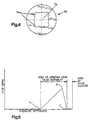
- Fig. 5 is a graph depicting the flow of hydraulic fluid through the pressure relief valve of the system of the present invention.
-
- Fig. 1 is a schematic illustration of a hydraulic
power steering system 10 embodying the present invention. Thesystem 10 includes ahydraulic steering gear 12 and apressure relief valve 14. Thesteering gear 12 and thepressure relief valve 14 are in parallel connection to one another in thesystem 10. Both thesteering gear 12 and thepressure relief valve 14 receive fluid from apump 16 that is connected to afluid reservoir 18. - A
feed line 86 extends from thereservoir 18 to the inlet of thepump 16. The outlet of thepump 16 is in fluid communication with aconduit 88.Conduit 88 communicates withconduits steering gear 12 and thepressure relief valve 14, respectively. Theconduit 90 communicates with aninlet 38 of thesteering gear 12, andconduit 92 communicates with aninlet 50 of thepressure relief valve 14. -
Conduit 94 is in fluid communication withoutlets steering gear 12 and thepressure relief valve 14, respectively. Afirst conduit 96 and asecond conduit 98 extend from theoutlets steering gear 12 and thepressure relief valve 14, respectively, and communicate with theconduit 94.Conduit 94 communicates with thereservoir 18. - Fig. 2 illustrates the
steering gear 12 of thesystem 10. As those skilled in the art will recognize, thesteering gear 12 of Fig. 2 is for illustrative purposes only. Thesystem 10 of the present invention may incorporate any suitable hydraulic steering gear. - The
steering gear 12 has ahousing 20 with an innercylindrical surface 22 defining a chamber. Apiston 24 is located within the chamber and divides the chamber intoopposite chamber portions chamber portion piston 24. Thepiston 24 creates a seal between therespective chamber portions piston 24 is caused by a pressure differential across the piston (betweenchamber portions 26 and 28). As thepiston 24 moves axially an increase in volume of one portion of thechamber chamber - A series of
rack teeth 30 is formed on the periphery of thepiston 24. Therack teeth 30 mesh with theteeth 32 formed on asector gear 34. Thesector gear 34 is fixed on anoutput shaft 36 that extends outwardly through an opening (not shown) in thehousing 20. Theoutput shaft 36 is typically connected to a pitman arm (not shown) that is connected to the steering linkage (not shown) of the vehicle. Thus, as thesector gear 34 rotates, theoutput shaft 36 is rotated to operate the steering linkage. As a result, the steerable wheels are turned. - The
housing 20 of thesteering gear 12 includes theinlet 38 and theoutlet 40. Theinlet 38 is in fluid communication with thepump 16 and is in fluid communication with adirectional control valve 42 of thesteering gear 12. - The
directional control valve 42 is also known as a steering valve. Thedirectional control valve 42 includes relativelyrotatable valve members member 42a rotates in response to rotation of the steering wheel of the vehicle. Valvemember 42b rotates in a follow-up manner as is known. Thevalve members chamber portions - The flow of hydraulic fluid to one of the
chamber portions chamber portion piston 24 to move axially. Thepiston 24 moves axially until the pressure within thechamber portions valve member 42b rotates due to axial movement of thepiston 24 that causes rotation ofscrew 42c, which is connected to and rotatesvalve member 42b. As the volume of onechamber portion other chamber portion directional control valve 42. This fluid exits from thedirectional control valve 42 and thehousing 20 of thesteering gear 12 through theoutlet 40. - Fig. 3 illustrates an embodiment of the
pressure relief valve 14 of thesystem 10. Those skilled in the art will recognize that thesystem 10 may incorporate a pressure relief valve of a different construction. - The
pressure relief valve 14 includes avalve body 44, avalve plug 46, and avalve stem assembly 48. Thevalve body 44 is a hollow, cylindrical body formed of an outercylindrical surface 45 and an innercylindrical surface 47. Acylindrical valve chamber 54 is defined by the innercylindrical surface 47. - The
valve body 44 includes three openings. A first opening is threaded to receive thevalve plug 46. The first opening is located on afirst end 53 of thecylindrical valve body 44 and is defined by the innercylindrical surface 47 of thevalve body 44. The second and third openings form thevalve inlet 50 and thevalve outlet 52, respectively. Thevalve inlet 50 is an opening that extends through thecylindrical surfaces valve body 44 and allows fluid flow into acylindrical valve chamber 54. Thevalve outlet 52 is located on asecond end 58 of thevalve body 44 and allows fluid flow out of thechamber 54. - A ledge 56 extends radially inwardly from the inner
cylindrical surface 47 into thecylindrical valve chamber 54 at thesecond end 58 of thevalve body 44 near thevalve outlet 52. The ledge 56 extends axially approximately 20% of the length of thechamber 54. The ledge 56 has an axially extending,cylindrical ledge surface 57 and a radially extending,annular ledge surface 59. The diameter of thechamber 54 is reduced in the area containing the ledge 56 by 25% to 40%. The diameter of thevalve outlet 52 is approximately 50% of the diameter of thechamber 54 in the area of the ledge 56. - A
groove 60 is located on the outercylindrical surface 45 of thevalve body 44 between thevalve inlet 50 and thevalve outlet 52. Preferably, thegroove 60 is located in the area of thevalve body 44 near the ledge 56. Thegroove 60 contains a seal for sealing between thevalve body 44 and theconduit 98 that may be attached to thepressure relief valve 14. - The
valve plug 46 has a threadedportion 49 for connecting with the first opening of thevalve body 44. Aseal 62 is placed between thevalve body 44 and thevalve plug 46 to seal the threaded connection. - The valve stem
assembly 48 includes avalve stem 64, aflow disk 66, and aprimary spring 68. The valve stem 64 is a long, cylindrical rod having afirst end 65 that is threaded and asecond end 67 with a sealingcylinder 70. The sealingcylinder 70 is a cylindrical portion of thevalve stem 64 that extends radially outwardly from the cylindrical rod and has a diameter greater than the diameter of thevalve outlet 52. - As shown in Fig. 4, the
flow disk 66 has a central,circular opening 72 and a plurality of flow vanes 74. The flow vanes are four semi-circular openings that are equally spaced apart around theopening 72 and extend radially outwardly from theopening 72 and are in fluid communication withopening 72. The flow vanes are optional. Theopening 72 of theflow disk 66 is sized to receive the cylindrical rod of thevalve stem 64 but is small enough to be sealed by the sealingcylinder 70 when the sealingcylinder 70 engages the lower side of theflow disk 66, as viewed in Fig. 3. If flow vanes 74 are provided, theflow vanes 74 are not sealed by the engagement of the sealingcylinder 70 with the lower side of theflow disk 66, as viewed in Fig. 3. - The
flow disk 66 has an outer diameter that is larger than the diameter of thevalve body 44 measured at the ledge 56 but is smaller than the diameter of thevalve body 44 measured away from the ledge 56. - The
primary spring 68 is a helically wound compression spring. The diameter of the helix of theprimary spring 68 is large enough to receive the cylindrical rod of thevalve stem 64 but is small enough to fit within thechamber 54 of thevalve body 44. - When the
valve stem assembly 48 is assembled, thevalve stem 64 is inserted into theopening 72 of theflow disk 66 so that theflow disk 62 rests on afirst surface 76 of the sealingcylinder 70. The valve stem 64 is then inserted through the center of the helix of theprimary spring 68 until an end of theprimary spring 68 rests on theflow disk 66. A retainingnut 78 is threaded onto thefirst end 65 of thevalve stem 64. The retainingnut 78 contacts the other end of theprimary spring 68 and compresses theprimary spring 68 between the retainingnut 78 and theflow disk 66. The retainingnut 78 can be tightened or loosened on thefirst end 65 of thevalve stem 64 to adjust the level of compression of theprimary spring 68. The compressedprimary spring 68 forces theflow disk 66 against afirst sealing face 76 of the sealingcylinder 70. - When the
pressure relief valve 14 is assembled, a cylindrical,adjustable shim 80 is placed on theradially extending surface 59 of the ledge 56 of thevalve body 44. The valve stemassembly 48 is then inserted into thechamber 54 so that theflow disk 66 is pressed against theadjustable shim 80. Asecondary spring 84 is placed on thefirst end 65 of thevalve stem 64 above the retainingnut 78 and is attached to thevalve plug 46. Thesecondary spring 84 is a helical compression spring. When thevalve plug 46 is threaded onto thevalve body 44, the secondary spring forces thevalve stem 64 away from thevalve plug 46 and toward thevalve outlet 52 such that theflow disk 66 seals against theadjustable shim 80. - During operation of the
power steering system 10 of the vehicle, thepump 16 draws hydraulic fluid from thereservoir 18 and pumps it into theconduit 88 andconduits inlets steering gear 12 and thepressure relief valve 14, respectively. The hydraulic fluid flows through thesteering gear 12 and exits the steering gear throughoutlet 40 into theconduit 96. If thepressure relief valve 14 hasflow vanes 74 in theflow disk 66 or thepressure relief valve 14 is in an actuated condition, fluid exits the pressure relief valve throughconduit 98. The hydraulic fluid entersconduit 94 and is returned to thereservoir 18. - When a pressure rise occurs in the
steering gear 12 due to resistance to turning of the steerable wheels of the vehicle, the pressure increases in theconduits steering gear inlet 38 and the pressurerelief valve inlet 50. The increase in pressure at theinlet 50 of thepressure relief valve 14 increases the pressure in thechamber 54 of thepressure relief valve 14. When a predetermined pressure differential is reached across the pressure relief valve 14(between theinlet 50 and the outlet 52), thepressure relief valve 14 actuates. The predetermined pressure differential at which the pressure relief valve actuates is also the pressure differential across thesteering gear 12 because the pressure at theinlet 50 of thepressure relief valve 14 corresponds to the pressure at theinlet 38 of the steering gear and the pressure at theoutlet 52 of the pressure relief valve corresponds with the pressure at theoutlet 40 of the steering gear. Thus, thepressure relief valve 14 actuates when there is a predetermined pressure differential across thesteering gear 12. - Operation of the
pressure relief valve 14 is described with reference to Figs. 3-5. In an unactuated condition, the first sealingface 76 of the sealingcylinder 70 is pressed against theflow disk 66 such that the first sealingface 76 completely blocks theopening 72 in theflow disk 66. If theflow disk 66 hasflow vanes 74, there is restricted fluid flow through thepressure relief valve 14 when thepressure relief valve 14 is in an unactuated condition since fluid flows through theflow vanes 74 of theflow disk 66. If theflow disk 66 does not haveflow vanes 74, all fluid flow through thepressure relief valve 14 is blocked when thepressure relief valve 14 is in an unactuated condition. - When the predetermined pressure differential between the
valve inlet 50 and thevalve outlet 52 is reached, thevalve stem 64, including the sealingcylinder 70, moves downward and away from theflow disk 66. The downward movement removes the sealingcylinder 70 from contact with theflow disk 66 allowing hydraulic fluid to flow through theopening 72 to thevalve outlet 52. This flow of hydraulic fluid decreases the pressure differential between theinlets outlets steering gear 12 and thepressure relief valve 14. The spring constant of theprimary spring 68, the tension applied onto theprimary spring 68 by the retainingnut 78, and the surface area of the sealingcylinder 70 subject to the pressure of the hydraulic fluid determine the predetermined pressure differential at which thevalve stem 64 moves downward. - The
pressure relief valve 14 has a plurality of actuated positions. Thepressure relief valve 14 is actuated when thevalve stem 64 moves away from theflow disk 66. As the pressure differential across thepressure relief valve 14 increases, thevalve stem 64 moves progressively away from theflow disk 66 and toward thesecond end 58 of thevalve body 44. - When in an actuated condition, the amount of flow through the
pressure relief valve 14 is limited by the smaller of two gaps. The first gap is formed between the first sealingface 76 of the sealingcylinder 70 and theflow disk 66. The second gap is formed between asecond sealing face 82 of the sealingcylinder 70 and thesecond end 58 of thevalve body 44. - As shown in Fig. 5, when the pressure differential across the
pressure relief valve 14 reaches the predetermined level (shown by A), thepressure relief valve 14 is actuated and fluid begins to flow through thepressure relief valve 14. The fluid flow through thepressure relief valve 14 increases as the pressure differential increases until a second predetermined pressure differential (shown by B) is reached. The second predetermined pressure differential occurs when there is an equal amount of fluid flow through both the first gap and the second gap. After the second predetermined pressure differential is reached, a further increase in the pressure differential causes the sealingcylinder 70 to move progressively closer to thesecond end 58 of thevalve body 44 and to begin to restrict the fluid flow through thepressure relief valve 14. When thepressure relief valve 14 is actuated such that the second sealing face 82 seals against thesecond end 58 of the valve body 44 (shown by C), fluid flow through thepressure relief valve 14 is completely blocked. - As the vehicle driver turns the steering wheel, there is relative rotary displacement of the
valve members chamber portion valve members valve members chamber portions pressure relief valve 14 reduces the pressure fluctuations at high pressure by providing some fluid communication between the steeringgear inlet 38 andsteering gear outlet 40. - The pressure fluctuations that are to be reduced may occur at different pressures in different vehicles. The adjustment of the
primary spring 68 in thepressure relief valve 14 will change the pressure at which thepressure relief valve 14 actuates. Thus, thepressure relief valve 14 may be used in different vehicles and adjusted for the particular vehicle in which it is used. - From the above description of the invention, those skilled in the art will perceive improvements, changes and modifications. Such improvements, changes and modifications within the skill of the art are intended to be covered by the appended claims.
Claims (12)
- A hydraulic power steering system for turning steerable wheels of a vehicle, the system comprising:a steering gear including a hydraulic motor actuatable to turn the steerable vehicle wheels and a steering valve for controlling actuation of the hydraulic motor by controlling fluid flow to the hydraulic motor, the steering gear having an inlet in communication with a fluid source and an outlet for directing fluid from the steering gear back to the fluid source, the steering gear being susceptible to pressure fluctuations that cause noise during steering; anda pressure relief valve having an unactuated condition and actuated conditions, the pressure relief valve in the unactuated condition restricting fluid flow through the pressure relief valve and in an actuated condition permitting fluid flow through the pressure relief valve, the pressure relief valve progressively moving from the unactuated condition to an actuated condition as a pressure differential between the inlet and the outlet of the steering gear increases, the pressure relief valve when in an actuated condition providing fluid communication between the inlet and the outlet of the steering gear while circumventing the steering gear to minimize the pressure fluctuations in the steering gear.
- The hydraulic power steering system in claim 1, further being defined by:
the pressure relief valve including a valve stem movable to control the fluid flow through the pressure relief valve. - The hydraulic power steering system in claim 2, further being defined by:
a spring being responsive to the pressure differential and controlling the movement of the valve stem. - The hydraulic power steering system in claim 3, further being defined by:
the pressure differential at which the valve stem moves being adjustable. - The hydraulic power steering system in claim 1, further being defined by:
the pressure relief valve when in the unactuated condition blocking fluid flow through the pressure relief valve. - The hydraulic power steering system in claim 5, further being defined by:
the pressure relief valve having a valve stem and a flow disk, in the unactuated condition the valve stem seating against the flow disk to block fluid flow through the pressure relief valve. - The hydraulic power steering system in claim 1, further being defined by:
the pressure relief valve when in the unactuated condition permitting restricted fluid flow through the pressure relief valve. - The hydraulic power steering system in claim 7, further being defined by:
the pressure relief valve having a valve stem and a flow disk, a plurality of flow vanes extending through the flow disk, in the unactuated condition the valve stem seating against the flow disk and allowing restricted fluid flow through the pressure relief valve. - The hydraulic power steering system in claim 1, further being defined by:
the pressure relief valve when in an actuated condition permitting fluid flow through the pressure relief valve. - The hydraulic power steering system in claim 9, further being defined by:
the pressure relief valve having a valve stem and a flow disk, in an actuated condition the valve stem being separated from the flow disk to permit fluid flow through the pressure relief valve. - The hydraulic power steering system in claim 1, further being defined by:
the pressure relief valve when in an actuated condition blocking fluid flow through the pressure relief valve. - The hydraulic power steering systsm in claim 11, further being defined by:
the pressure relief valve having a valve body and a valve stem, the valve body defining a chamber and having an end with a valve outlet, the valve stem being located within the chamber of the valve body, in an actuated condition the valve stem seating against the end of the valve body to block fluid flow through the valve outlet.
Applications Claiming Priority (2)
| Application Number | Priority Date | Filing Date | Title |
|---|---|---|---|
| US09/595,836 US6394219B1 (en) | 2000-06-16 | 2000-06-16 | Hydraulic power steering system with a pressure relief valve |
| US595836 | 2000-06-16 |
Publications (2)
| Publication Number | Publication Date |
|---|---|
| EP1177967A1 true EP1177967A1 (en) | 2002-02-06 |
| EP1177967B1 EP1177967B1 (en) | 2005-11-30 |
Family
ID=24384871
Family Applications (1)
| Application Number | Title | Priority Date | Filing Date |
|---|---|---|---|
| EP01114493A Expired - Lifetime EP1177967B1 (en) | 2000-06-16 | 2001-06-15 | Hydraulic power steering system with a pressure relief valve |
Country Status (5)
| Country | Link |
|---|---|
| US (1) | US6394219B1 (en) |
| EP (1) | EP1177967B1 (en) |
| BR (1) | BR0102389A (en) |
| DE (1) | DE60115340T2 (en) |
| ES (1) | ES2256120T3 (en) |
Families Citing this family (6)
| Publication number | Priority date | Publication date | Assignee | Title |
|---|---|---|---|---|
| US20070137923A1 (en) * | 2005-12-19 | 2007-06-21 | Dennis Kenneth J | Method and apparatus for enhancing vehicle performance |
| US20070175523A1 (en) * | 2006-01-31 | 2007-08-02 | Levey Kenneth R | Pressure relief assembly |
| AU2007100088A4 (en) * | 2006-02-06 | 2007-03-08 | Truck Whisperer Limited | Method and apparatus for enhancing car performance |
| US20080277187A1 (en) * | 2007-05-11 | 2008-11-13 | Trw Automotive U.S. Llc | Power steering apparatus |
| US20100018796A1 (en) * | 2008-07-22 | 2010-01-28 | Trw Automotive U.S. Llc | Apparatus for controlling a power-assisted steering gear in response to vehicle conditions |
| US9156494B2 (en) * | 2013-10-18 | 2015-10-13 | GM Global Technology Operations LLC | Vehicle steering systems |
Citations (4)
| Publication number | Priority date | Publication date | Assignee | Title |
|---|---|---|---|---|
| US2030902A (en) * | 1930-10-20 | 1936-02-18 | Harry F Vickers | Hydraulic steering gear |
| US3242824A (en) * | 1963-07-31 | 1966-03-29 | Zahnradfabrik Friedrichshafen | Hydraulic power steering system |
| DE1810550A1 (en) * | 1968-11-23 | 1970-06-04 | Ernst Heinkel Ag | Cone seat valve |
| EP0818380A2 (en) * | 1996-07-09 | 1998-01-14 | Toyota Jidosha Kabushiki Kaisha | Power steering apparatus having an easily adjustable counter force mechanism |
Family Cites Families (14)
| Publication number | Priority date | Publication date | Assignee | Title |
|---|---|---|---|---|
| US2688978A (en) * | 1950-06-20 | 1954-09-14 | Detroit Controls Corp | Liquid flow check valve |
| US2769457A (en) * | 1953-06-01 | 1956-11-06 | Nat Presto Ind | Combined venting and overpressure release valve |
| US3892254A (en) * | 1972-02-01 | 1975-07-01 | Johnson Service Co | Diaphragm valve apparatus and control systems employing such valve apparatus |
| US4394945A (en) * | 1981-08-06 | 1983-07-26 | Loctite Corporation | Valve having suck-back feature |
| US4542768A (en) * | 1984-03-12 | 1985-09-24 | Rotron, Inc. | Pressure relief valve |
| US4609330A (en) * | 1985-04-04 | 1986-09-02 | Federal Supply And Equipment Company | Modular unloading sequencing switching valve assembly for hydraulic system |
| US4633853A (en) * | 1985-05-06 | 1987-01-06 | Leonard Prill | Hot water tank check valve |
| JPS62152972A (en) * | 1985-12-27 | 1987-07-07 | Toyoda Mach Works Ltd | Hydraulic reactional controller for steering force |
| US5183075A (en) * | 1986-04-12 | 1993-02-02 | Stein Guenter | Check valve |
| US4773303A (en) * | 1987-12-21 | 1988-09-27 | Trw Inc. | Apparatus and method for readjusting pressure relief poppet valves |
| IL110288A0 (en) * | 1994-07-12 | 1994-10-21 | Bron Dan | Self-cleaning inlet head for a fluid |
| US5553683A (en) * | 1995-01-20 | 1996-09-10 | Applied Power Inc. | Variable assist power steering system with electro-hydraulic working pressure and directional pressure control |
| US6123101A (en) * | 1997-05-14 | 2000-09-26 | Magne-Flo Corporation | Spring body excess flow valve |
| JP2000072011A (en) * | 1998-09-04 | 2000-03-07 | Showa Corp | Dumper valve for hydraulic power steering |
-
2000
- 2000-06-16 US US09/595,836 patent/US6394219B1/en not_active Expired - Fee Related
-
2001
- 2001-06-13 BR BR0102389-6A patent/BR0102389A/en not_active IP Right Cessation
- 2001-06-15 EP EP01114493A patent/EP1177967B1/en not_active Expired - Lifetime
- 2001-06-15 DE DE60115340T patent/DE60115340T2/en not_active Expired - Fee Related
- 2001-06-15 ES ES01114493T patent/ES2256120T3/en not_active Expired - Lifetime
Patent Citations (4)
| Publication number | Priority date | Publication date | Assignee | Title |
|---|---|---|---|---|
| US2030902A (en) * | 1930-10-20 | 1936-02-18 | Harry F Vickers | Hydraulic steering gear |
| US3242824A (en) * | 1963-07-31 | 1966-03-29 | Zahnradfabrik Friedrichshafen | Hydraulic power steering system |
| DE1810550A1 (en) * | 1968-11-23 | 1970-06-04 | Ernst Heinkel Ag | Cone seat valve |
| EP0818380A2 (en) * | 1996-07-09 | 1998-01-14 | Toyota Jidosha Kabushiki Kaisha | Power steering apparatus having an easily adjustable counter force mechanism |
Also Published As
| Publication number | Publication date |
|---|---|
| DE60115340D1 (en) | 2006-01-05 |
| BR0102389A (en) | 2002-02-19 |
| ES2256120T3 (en) | 2006-07-16 |
| US6394219B1 (en) | 2002-05-28 |
| EP1177967B1 (en) | 2005-11-30 |
| DE60115340T2 (en) | 2006-08-24 |
Similar Documents
| Publication | Publication Date | Title |
|---|---|---|
| JP4004545B2 (en) | Piston pump | |
| US20080034910A1 (en) | Dynamic adjustment of a steering system yoke | |
| EP0321756B1 (en) | Apparatus and method for readjusting pressure relief poppet valves | |
| US5419235A (en) | Power steering gear assembly | |
| US6394219B1 (en) | Hydraulic power steering system with a pressure relief valve | |
| GB2044697A (en) | Valve Assembly for Power Assisted Steering Gear | |
| US6993904B2 (en) | Integrated valve system | |
| US4410059A (en) | Fluid-operated control apparatus for power-assisted steering system of automotive vehicle | |
| EP1295779B1 (en) | Rack and pinion steering gear with powdered metal bushing | |
| US5582207A (en) | Steering control valve with flow gaps which change relative size for noise suppression | |
| EP0592095B1 (en) | Steering control valve with contoured control surfaces | |
| US4418779A (en) | Control apparatus for vehicle steering system | |
| US5857478A (en) | Demand responsive flow control valve | |
| US4487281A (en) | Power-assisted rack-and-pinion steering mechanism | |
| EP0585107A1 (en) | Steering control valve with contoured control surfaces | |
| US5562124A (en) | Steering control valve with different size flow gaps for noise suppression | |
| EP0752361B1 (en) | Flow control device | |
| US6152179A (en) | Manually operable hydraulic pilot control | |
| US6213730B1 (en) | Flow control apparatus for a hydraulic pump | |
| JP3944454B2 (en) | Damper valve for hydraulic power steering system | |
| US2893505A (en) | Hydraulic reaction control in a power steering system | |
| US20040195036A1 (en) | Power steering motor having a noise dampening piston assembly | |
| US9315209B1 (en) | Hydraulically assisted steering system | |
| CA2172018C (en) | Steering control valve with flow gaps which change relative size for noise suppression | |
| EP0405860A1 (en) | Power assisted steering mechanism |
Legal Events
| Date | Code | Title | Description |
|---|---|---|---|
| PUAI | Public reference made under article 153(3) epc to a published international application that has entered the european phase |
Free format text: ORIGINAL CODE: 0009012 |
|
| AK | Designated contracting states |
Kind code of ref document: A1 Designated state(s): DE ES FR GB Kind code of ref document: A1 Designated state(s): AT BE CH CY DE DK ES FI FR GB GR IE IT LI LU MC NL PT SE TR |
|
| AX | Request for extension of the european patent |
Free format text: AL;LT;LV;MK;RO;SI |
|
| 17P | Request for examination filed |
Effective date: 20020729 |
|
| AKX | Designation fees paid |
Free format text: DE ES FR GB |
|
| 17Q | First examination report despatched |
Effective date: 20030520 |
|
| RAP1 | Party data changed (applicant data changed or rights of an application transferred) |
Owner name: TRW AUTOMOTIVE U.S. LLC |
|
| GRAP | Despatch of communication of intention to grant a patent |
Free format text: ORIGINAL CODE: EPIDOSNIGR1 |
|
| GRAS | Grant fee paid |
Free format text: ORIGINAL CODE: EPIDOSNIGR3 |
|
| GRAA | (expected) grant |
Free format text: ORIGINAL CODE: 0009210 |
|
| AK | Designated contracting states |
Kind code of ref document: B1 Designated state(s): DE ES FR GB |
|
| REG | Reference to a national code |
Ref country code: GB Ref legal event code: FG4D |
|
| REF | Corresponds to: |
Ref document number: 60115340 Country of ref document: DE Date of ref document: 20060105 Kind code of ref document: P |
|
| PGFP | Annual fee paid to national office [announced via postgrant information from national office to epo] |
Ref country code: GB Payment date: 20060505 Year of fee payment: 6 |
|
| PGFP | Annual fee paid to national office [announced via postgrant information from national office to epo] |
Ref country code: FR Payment date: 20060605 Year of fee payment: 6 |
|
| PGFP | Annual fee paid to national office [announced via postgrant information from national office to epo] |
Ref country code: ES Payment date: 20060616 Year of fee payment: 6 |
|
| REG | Reference to a national code |
Ref country code: ES Ref legal event code: FG2A Ref document number: 2256120 Country of ref document: ES Kind code of ref document: T3 |
|
| ET | Fr: translation filed | ||
| PLBE | No opposition filed within time limit |
Free format text: ORIGINAL CODE: 0009261 |
|
| STAA | Information on the status of an ep patent application or granted ep patent |
Free format text: STATUS: NO OPPOSITION FILED WITHIN TIME LIMIT |
|
| 26N | No opposition filed |
Effective date: 20060831 |
|
| GBPC | Gb: european patent ceased through non-payment of renewal fee |
Effective date: 20070615 |
|
| REG | Reference to a national code |
Ref country code: FR Ref legal event code: ST Effective date: 20080229 |
|
| PG25 | Lapsed in a contracting state [announced via postgrant information from national office to epo] |
Ref country code: GB Free format text: LAPSE BECAUSE OF NON-PAYMENT OF DUE FEES Effective date: 20070615 |
|
| REG | Reference to a national code |
Ref country code: ES Ref legal event code: FD2A Effective date: 20070616 |
|
| PG25 | Lapsed in a contracting state [announced via postgrant information from national office to epo] |
Ref country code: FR Free format text: LAPSE BECAUSE OF NON-PAYMENT OF DUE FEES Effective date: 20070702 |
|
| PG25 | Lapsed in a contracting state [announced via postgrant information from national office to epo] |
Ref country code: ES Free format text: LAPSE BECAUSE OF NON-PAYMENT OF DUE FEES Effective date: 20070616 |
|
| PGFP | Annual fee paid to national office [announced via postgrant information from national office to epo] |
Ref country code: DE Payment date: 20080630 Year of fee payment: 8 |
|
| PG25 | Lapsed in a contracting state [announced via postgrant information from national office to epo] |
Ref country code: DE Free format text: LAPSE BECAUSE OF NON-PAYMENT OF DUE FEES Effective date: 20100101 |