EP1177855A2 - Indexing mechanism - Google Patents
Indexing mechanism Download PDFInfo
- Publication number
- EP1177855A2 EP1177855A2 EP01306591A EP01306591A EP1177855A2 EP 1177855 A2 EP1177855 A2 EP 1177855A2 EP 01306591 A EP01306591 A EP 01306591A EP 01306591 A EP01306591 A EP 01306591A EP 1177855 A2 EP1177855 A2 EP 1177855A2
- Authority
- EP
- European Patent Office
- Prior art keywords
- detent
- disc
- pawl
- indexing device
- lever
- Prior art date
- Legal status (The legal status is an assumption and is not a legal conclusion. Google has not performed a legal analysis and makes no representation as to the accuracy of the status listed.)
- Withdrawn
Links
Images


Classifications
-
- B—PERFORMING OPERATIONS; TRANSPORTING
- B23—MACHINE TOOLS; METAL-WORKING NOT OTHERWISE PROVIDED FOR
- B23Q—DETAILS, COMPONENTS, OR ACCESSORIES FOR MACHINE TOOLS, e.g. ARRANGEMENTS FOR COPYING OR CONTROLLING; MACHINE TOOLS IN GENERAL CHARACTERISED BY THE CONSTRUCTION OF PARTICULAR DETAILS OR COMPONENTS; COMBINATIONS OR ASSOCIATIONS OF METAL-WORKING MACHINES, NOT DIRECTED TO A PARTICULAR RESULT
- B23Q16/00—Equipment for precise positioning of tool or work into particular locations not otherwise provided for
- B23Q16/02—Indexing equipment
- B23Q16/04—Indexing equipment having intermediate members, e.g. pawls, for locking the relatively movable parts in the indexed position
- B23Q16/06—Rotary indexing
-
- B—PERFORMING OPERATIONS; TRANSPORTING
- B23—MACHINE TOOLS; METAL-WORKING NOT OTHERWISE PROVIDED FOR
- B23Q—DETAILS, COMPONENTS, OR ACCESSORIES FOR MACHINE TOOLS, e.g. ARRANGEMENTS FOR COPYING OR CONTROLLING; MACHINE TOOLS IN GENERAL CHARACTERISED BY THE CONSTRUCTION OF PARTICULAR DETAILS OR COMPONENTS; COMBINATIONS OR ASSOCIATIONS OF METAL-WORKING MACHINES, NOT DIRECTED TO A PARTICULAR RESULT
- B23Q16/00—Equipment for precise positioning of tool or work into particular locations not otherwise provided for
- B23Q16/02—Indexing equipment
- B23Q16/04—Indexing equipment having intermediate members, e.g. pawls, for locking the relatively movable parts in the indexed position
- B23Q16/046—Indexing equipment having intermediate members, e.g. pawls, for locking the relatively movable parts in the indexed position with a continuous drive
-
- B—PERFORMING OPERATIONS; TRANSPORTING
- B23—MACHINE TOOLS; METAL-WORKING NOT OTHERWISE PROVIDED FOR
- B23Q—DETAILS, COMPONENTS, OR ACCESSORIES FOR MACHINE TOOLS, e.g. ARRANGEMENTS FOR COPYING OR CONTROLLING; MACHINE TOOLS IN GENERAL CHARACTERISED BY THE CONSTRUCTION OF PARTICULAR DETAILS OR COMPONENTS; COMBINATIONS OR ASSOCIATIONS OF METAL-WORKING MACHINES, NOT DIRECTED TO A PARTICULAR RESULT
- B23Q5/00—Driving or feeding mechanisms; Control arrangements therefor
- B23Q5/22—Feeding members carrying tools or work
- B23Q5/34—Feeding other members supporting tools or work, e.g. saddles, tool-slides, through mechanical transmission
-
- Y—GENERAL TAGGING OF NEW TECHNOLOGICAL DEVELOPMENTS; GENERAL TAGGING OF CROSS-SECTIONAL TECHNOLOGIES SPANNING OVER SEVERAL SECTIONS OF THE IPC; TECHNICAL SUBJECTS COVERED BY FORMER USPC CROSS-REFERENCE ART COLLECTIONS [XRACs] AND DIGESTS
- Y10—TECHNICAL SUBJECTS COVERED BY FORMER USPC
- Y10T—TECHNICAL SUBJECTS COVERED BY FORMER US CLASSIFICATION
- Y10T74/00—Machine element or mechanism
- Y10T74/14—Rotary member or shaft indexing, e.g., tool or work turret
- Y10T74/1418—Preselected indexed position
-
- Y—GENERAL TAGGING OF NEW TECHNOLOGICAL DEVELOPMENTS; GENERAL TAGGING OF CROSS-SECTIONAL TECHNOLOGIES SPANNING OVER SEVERAL SECTIONS OF THE IPC; TECHNICAL SUBJECTS COVERED BY FORMER USPC CROSS-REFERENCE ART COLLECTIONS [XRACs] AND DIGESTS
- Y10—TECHNICAL SUBJECTS COVERED BY FORMER USPC
- Y10T—TECHNICAL SUBJECTS COVERED BY FORMER US CLASSIFICATION
- Y10T74/00—Machine element or mechanism
- Y10T74/14—Rotary member or shaft indexing, e.g., tool or work turret
- Y10T74/1494—Locking means
Definitions
- the present invention relates to an indexing mechanism for providing discrete predetermined positions of rest for an object or objects.
- the mechanism of the invention relates particularly but not exclusively to the field of optical measurement, or spectroscopic analysis.
- Indexing mechanisms of various forms are known.
- One common approach for rotating indexing is to use a rotary encoder and stop rotation when a certain angular position is reached.
- indexing table used to support optical elements
- a mechanism is supplemented by an arrangement including a sprung ball biased into a recess to positively hold the table in one indexed position.
- this recess may be ramped, the force of the bias on the ball is difficult to overcome when resumption of rotation is carried out, and a high torque is required to push the ball out of the recess to resume turning. Additionally the bias force on the ball has a bending moment on the table support bearings which can cause positional errors.
- Preferred embodiments of the invention address at least the above problems.
- an indexing mechanism comprising a member movable in a first direction relative to a fixed structure and in a second direction opposite to said first direction;
- the member is a disc rotatable about a central axis.
- the member is moved with respect to the fixed structure by a motor and drive means.
- the driving means may comprise a lever pivoted on a fixed surface, wherein the lever interacts with a plurality of elements disposed about the axis of the disc; wherein if the lever is moved in a first direction, a first surface of the lever contacts a first surface of an element and pushes the disc in the first direction and wherein if the lever moves in a second direction, a second surface of the lever contacts a second surface of an element and pushes the disc in the second direction.
- Movement of the lever may be controlled by a wire attached to the lever at one end and to a fixed point at the other end, wherein the length of the wire is altered by applying heat to the wire.
- a stop is provided on the member adjacent each detent wherein the stop defines the position of the pawl relative to the member.
- Point contact is made between the first element and second element.
- Point contact may be made between the second element and the stop.
- first element and/or second element are profiled to prevent sliding contact therebetween at locations where point contact takes place.
- a rotary table for supporting optical elements, the table being indexable by means of ratchet mechanism.
- a first embodiment of the invention which comprises an indexable table 2 which in use will be used to support objects, e.g. optical apparatus.
- the table which can be used in any orientation, is indexable to one of a number (in this case 6) positions, so that objects can be brought into use at one of the positions, and reintroduced subsequently in that exact same position.
- Exact rotational movement of the table is obtained by a precision bearing 6 and angular positioning is obtained using a mechanism shown in Fig 3 and discussed below.
- the bearing 6 may be of the type described in our copending UK patent application GB 0019200.5 filed on 5th August 2000.
- Bearing 6 is mounted to table support 4 which is in turn fixed to spectroscopic analysis apparatus or the like.
- the table is driven to rotate principally unidirectionally in the direction of arrow A by motor 12.
- the motor 12 is also fixed to the apparatus.
- a drive belt 16 operatively connects the motor 12 to the table 2.
- the table 2 has detents 8 at its periphery which in use co-operate with a fixed resilient pawl element 14.
- the detents may be mounted to the table in slots and may be secured in the slots with adhesive.
- the detents shown are in the form of a cylinder in this case a hardened steel roller.
- the pawl 14 is displaced to ride over a detent 8 as the table is driven and then into register with a detent 8 at detent/pawl contact point 9.
- the pawl to detent contact is obtained by reversing the direction of rotation of the table 2. This reversal may be effected by a change in motor driving direction. If the motor is reversed and the table is driven in the direction of arrow B a tension will be generated in the belt side 20, which will hold the pawl in contact with the detent when the motor is stopped.
- a slipping clutch may be used in the motor drive to prevent excessive loading on the pawl when reversing the motor drive after pawl/detent contact has been made.
- a light loading of the pawl/detent may be maintained either by residual tension in the belt and/or by reverse powering the motor, with or without a clutch.
- the table can be indexed to any one of six positions associated with detents 8.
- Motor 12 will be linked to a controller (not shown) which will include a table position monitoring device, for example a rotary encoder.
- a controller not shown
- the position of the table is known to the controller and repositioning to a suitable index position can be effected by rotation in direction A followed by a short rotation in direction B.
- a wear relief shoulder 24 is provided mounted on the outer end of detent 8.
- the shoulder has lips 26 which permit sliding contact only with the outer portions of the end of the pawl 14 and prevent rubbing at the contact region 9. In this way the contact portion of the pawl is not worn by sliding contact.
- the pawl 14 is positioned relative to the table by its mounting 18 and a stop 10 adjacent each detent 8. The pawl is biased by its resilience towards the stop so that it rests against the stop 10 when at an indexed position. The stop allows repeatable positioning of the table because the pawl will be in exactly the same place each time the table returns to one of its indexing positions.
- the ball may be fixed in a slot in the table and possibly secured with adhesive.
- the stops 10 shown are in the form of a sphere, in this case a hardened steel ball.
- Pawl 14 makes substantially point contact with each detent 8 and makes point contact with each stop 10, thus providing accurate and repeatable index positions.
- An indexing mechanism has the advantages of: low wear on position defining surfaces which gives high repeatability over many cycles of use; low torque drive requirements in comparison to prior art devices; a simple drive coupling; and low cost components providing an overall low manufacturing cost.
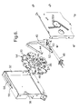
- An indexable wheel 30 is mounted in a housing 32 via a central bearing 34 (i.e. a high precision bearing).
- the wheel 30 has a plurality of apertures 36 evenly spaced on a circle about the central axis of the wheel to accommodate objects such as lenses.
- the housing 32 is provided with a window 38 such that the wheel 30 may be rotated to align each object in its aperture 36 with the window 38 in the housing 32.
- a lever 40 is provided which has the dual purpose of driving the wheel 30 to rotate about its axis such that successive apertures 36 are aligned with the window 38 on the housing 32 and also holding the wheel in a desired position.
- the lever 40 is pivoted at a pivot point 42 on the housing 32. At the distil end from the pivot point 42 the lever is provided with a shaped portion 44.
- the wheel 30 is provided with a number of protrusions 46 corresponding to the number of apertures 36.
- the protrusions 46 are also evenly spaced on a circle about the central axis of the wheel.
- Each protrusion has two edges 46A and 46B.
- the shaped portion 44 of the lever 40 has two surfaces 44A and 44B which are positioned to be contactable with the corresponding edges 46A,46B of each protrusion 46.
- the shaped portion 44 may be angled from the main body of the lever 40 to bring it to the correct position in relation to the wheel 30.
- a coiled spring 50 is provided which is attached at one end to the housing 32 and at another end to an arm 52 protruding from the lever 40. This coiled spring biases the lever in the direction of arrow B, shown in Fig 5.
- the lever may be biased in the direction of arrow B by other means, for example by using a weight under gravity.
- the lever is actuated by a memory wire 48 which is attached towards an end of the lever 40 remote from the shaped portion 44 at one end and fixed to the housing 32 at its other end.
- a current may be passed through the memory wire which reduces its length by approximately 3% by heating the wire above a transition temperature. When no current is passed through the wire and it cools below a transition temperature it returns to its unextended length.
- the lever may be actuated by other means, for example a solenoid or motor.
- the wheel 30 is provided with a set of stops 54 which extend from the circumference of the wheel 30, again evenly spaced on a circle about its central axis.
- the upper surface of the housing 32 has an aperture 56 and adjacent this aperture a u-shaped cut-out defines a spring 58.
- the stops 54 are positioned relative to protrusions 46 such that when surface 44B of the shaped portion 44 abuts edge 44B on a protrusion 46, the corresponding stop 54 abuts the spring 58.
- the position of the wheel is precisely defined by the combination of the lever 40 pulling the protrusion 46 in direction B and the stop 54 abutting spring 58. This precise position is held when no current passes through the memory wire 48 and it is cooled below its transition temperature.
- Stops 54 each have a rounded surface 54B on one side. This enables the wheel 30 to rotate in direction A without being impeded by the spring 58. In this direction the rounded surface 54B of the stop 54 is able to deflect the spring 58 as it passes, the spring 58 returning to its rest position once the stop 54 has passed.
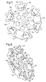
- Figs 7 and 8 show the wheel used in the invention.
- This wheel may be made from a flat sheet of metal which is folded into the desired configuration. Apertures and cut-outs may first be formed by, for example, chemi-etching.
- the apertures 36 are able to receive different shaped objects, for example a round object 70 or a square object 72 as shown in Figs 7 and 8.
- the object is inserted between surfaces 60,62 of the wheel 30.
- Surface 62 is a sprung surface and holds the object against surface 60.
- a stop 64 defines one end of the aperture. Sprung sides 66,68 of the aperture are deflected by the object as it is inserted into the aperture. These sprung sides are biased towards the object and hold it in position in the aperture.
Landscapes
- Engineering & Computer Science (AREA)
- Mechanical Engineering (AREA)
- Transmission Devices (AREA)
- Grinding And Polishing Of Tertiary Curved Surfaces And Surfaces With Complex Shapes (AREA)
- Lens Barrels (AREA)
- Microscoopes, Condenser (AREA)
- Machine Tool Positioning Apparatuses (AREA)
Abstract
Description
and wherein when the member is moved in the second direction the pawl abuts a detent to define an index position and the member is biased or driven in the second direction to retain this position.
Claims (13)
and wherein when the member (2,30) is moved in the second direction the pawl abuts a detent to define an index position;
characterised in that the member is biased or driven in the second direction to retain this position.
Applications Claiming Priority (2)
| Application Number | Priority Date | Filing Date | Title |
|---|---|---|---|
| GBGB0019199.9A GB0019199D0 (en) | 2000-08-05 | 2000-08-05 | Indexing mechanism |
| GB0019199 | 2000-08-05 |
Publications (2)
| Publication Number | Publication Date |
|---|---|
| EP1177855A2 true EP1177855A2 (en) | 2002-02-06 |
| EP1177855A3 EP1177855A3 (en) | 2003-01-15 |
Family
ID=9897011
Family Applications (1)
| Application Number | Title | Priority Date | Filing Date |
|---|---|---|---|
| EP01306591A Withdrawn EP1177855A3 (en) | 2000-08-05 | 2001-08-01 | Indexing mechanism |
Country Status (4)
| Country | Link |
|---|---|
| US (1) | US20020017161A1 (en) |
| EP (1) | EP1177855A3 (en) |
| JP (1) | JP2002137147A (en) |
| GB (1) | GB0019199D0 (en) |
Cited By (1)
| Publication number | Priority date | Publication date | Assignee | Title |
|---|---|---|---|---|
| US6860637B2 (en) | 2000-08-05 | 2005-03-01 | Renishaw Plc | Bearing arrangement |
Families Citing this family (2)
| Publication number | Priority date | Publication date | Assignee | Title |
|---|---|---|---|---|
| DE102007043778B4 (en) * | 2007-09-13 | 2016-04-28 | Felsomat Gmbh & Co. Kg | Gear hobbing machine with motor drive for applying holding force to a drum |
| CN110531477A (en) * | 2019-08-30 | 2019-12-03 | 北京临近空间飞行器系统工程研究所 | A kind of multicomponent high density filling device |
Family Cites Families (4)
| Publication number | Priority date | Publication date | Assignee | Title |
|---|---|---|---|---|
| US3158920A (en) * | 1963-01-16 | 1964-12-01 | Cincinnati Milling Machine Co | Automatically indexed tool turret |
| FR1575569A (en) * | 1968-02-07 | 1969-07-25 | ||
| DE2500638A1 (en) * | 1975-01-09 | 1976-07-15 | Wilfried Philipp | Pneumatically operated rotary indexing table - of low height with division plate and setting ring co-planar |
| US5647137A (en) * | 1993-04-22 | 1997-07-15 | Renishaw Plc | Probe arm for machine tool |
-
2000
- 2000-08-05 GB GBGB0019199.9A patent/GB0019199D0/en not_active Ceased
-
2001
- 2001-07-31 US US09/917,948 patent/US20020017161A1/en not_active Abandoned
- 2001-08-01 EP EP01306591A patent/EP1177855A3/en not_active Withdrawn
- 2001-08-03 JP JP2001236345A patent/JP2002137147A/en active Pending
Cited By (2)
| Publication number | Priority date | Publication date | Assignee | Title |
|---|---|---|---|---|
| US6860637B2 (en) | 2000-08-05 | 2005-03-01 | Renishaw Plc | Bearing arrangement |
| US7228641B2 (en) | 2000-08-05 | 2007-06-12 | Renishaw Plc | Bearing arrangement |
Also Published As
| Publication number | Publication date |
|---|---|
| EP1177855A3 (en) | 2003-01-15 |
| JP2002137147A (en) | 2002-05-14 |
| GB0019199D0 (en) | 2000-09-27 |
| US20020017161A1 (en) | 2002-02-14 |
Similar Documents
| Publication | Publication Date | Title |
|---|---|---|
| US5797317A (en) | Universal chuck for holding plates of various sizes | |
| US5682026A (en) | Multiple carousel carrier and carousel handling mechanism | |
| DE60209410D1 (en) | Shift position indicator for a bicycle | |
| EP1177855A2 (en) | Indexing mechanism | |
| US5680649A (en) | Lens driving device for auto-focus camera | |
| US6106068A (en) | Automatic device for index guiding a movable part pivotably mounted about an axis on a part considered to be stationary relative to said axis | |
| CA1099937A (en) | Variable step size impulse drive | |
| NO992937D0 (en) | Lawn mower with special wheel mechanism | |
| JP2003279827A (en) | Zoom lens barrel | |
| KR20030033111A (en) | Turn signal switching unit | |
| CA2299541C (en) | Bi-directional spring holder assembly for an actuator | |
| JP3861363B2 (en) | Optical element switching mechanism | |
| JPH073373Y2 (en) | Focus adjustment mechanism | |
| RU97101284A (en) | TAPE SWITCHING DEVICE WITH REVERSE | |
| US5586088A (en) | Metronome mechanism | |
| US7350693B2 (en) | Indexing mechanism | |
| US20050141071A1 (en) | Device for shifting the position of a swiveling holder | |
| JPS5936346Y2 (en) | work table equipment | |
| JPH0516350B2 (en) | ||
| US20040108641A1 (en) | Substrate holder | |
| JPH062073Y2 (en) | Rack and pinion transmission | |
| KR930001012Y1 (en) | Intermittent Rotation Transmission Device | |
| JPH0627438Y2 (en) | Track-type flexible parallel ruler, etc. | |
| US4729251A (en) | Stepping mechanism | |
| JPS61251722A (en) | Diffraction grating switching mechanism of spectrometer |
Legal Events
| Date | Code | Title | Description |
|---|---|---|---|
| PUAI | Public reference made under article 153(3) epc to a published international application that has entered the european phase |
Free format text: ORIGINAL CODE: 0009012 |
|
| AK | Designated contracting states |
Kind code of ref document: A2 Designated state(s): AT BE CH CY DE DK ES FI FR GB GR IE IT LI LU MC NL PT SE TR |
|
| AX | Request for extension of the european patent |
Free format text: AL;LT;LV;MK;RO;SI |
|
| PUAL | Search report despatched |
Free format text: ORIGINAL CODE: 0009013 |
|
| AK | Designated contracting states |
Kind code of ref document: A3 Designated state(s): AT BE CH CY DE DK ES FI FR GB GR IE IT LI LU MC NL PT SE TR |
|
| AX | Request for extension of the european patent |
Free format text: AL;LT;LV;MK;RO;SI |
|
| 17P | Request for examination filed |
Effective date: 20030715 |
|
| AKX | Designation fees paid |
Designated state(s): AT BE CH CY DE DK ES FI FR GB GR IE IT LI LU MC NL PT SE TR |
|
| 17Q | First examination report despatched |
Effective date: 20031205 |
|
| STAA | Information on the status of an ep patent application or granted ep patent |
Free format text: STATUS: THE APPLICATION IS DEEMED TO BE WITHDRAWN |
|
| 18D | Application deemed to be withdrawn |
Effective date: 20040616 |