EP1177810B1 - Appareil d'aide à la ventilation d'un patient - Google Patents
Appareil d'aide à la ventilation d'un patient Download PDFInfo
- Publication number
- EP1177810B1 EP1177810B1 EP01402065A EP01402065A EP1177810B1 EP 1177810 B1 EP1177810 B1 EP 1177810B1 EP 01402065 A EP01402065 A EP 01402065A EP 01402065 A EP01402065 A EP 01402065A EP 1177810 B1 EP1177810 B1 EP 1177810B1
- Authority
- EP
- European Patent Office
- Prior art keywords
- gas
- pressure
- assisting
- valve
- ventilation according
- Prior art date
- Legal status (The legal status is an assumption and is not a legal conclusion. Google has not performed a legal analysis and makes no representation as to the accuracy of the status listed.)
- Expired - Lifetime
Links
Images




Classifications
-
- A—HUMAN NECESSITIES
- A61—MEDICAL OR VETERINARY SCIENCE; HYGIENE
- A61M—DEVICES FOR INTRODUCING MEDIA INTO, OR ONTO, THE BODY; DEVICES FOR TRANSDUCING BODY MEDIA OR FOR TAKING MEDIA FROM THE BODY; DEVICES FOR PRODUCING OR ENDING SLEEP OR STUPOR
- A61M16/00—Devices for influencing the respiratory system of patients by gas treatment, e.g. ventilators; Tracheal tubes
- A61M16/20—Valves specially adapted to medical respiratory devices
-
- A—HUMAN NECESSITIES
- A61—MEDICAL OR VETERINARY SCIENCE; HYGIENE
- A61M—DEVICES FOR INTRODUCING MEDIA INTO, OR ONTO, THE BODY; DEVICES FOR TRANSDUCING BODY MEDIA OR FOR TAKING MEDIA FROM THE BODY; DEVICES FOR PRODUCING OR ENDING SLEEP OR STUPOR
- A61M16/00—Devices for influencing the respiratory system of patients by gas treatment, e.g. ventilators; Tracheal tubes
- A61M16/0057—Pumps therefor
- A61M16/0066—Blowers or centrifugal pumps
- A61M16/0069—Blowers or centrifugal pumps the speed thereof being controlled by respiratory parameters, e.g. by inhalation
-
- A—HUMAN NECESSITIES
- A61—MEDICAL OR VETERINARY SCIENCE; HYGIENE
- A61M—DEVICES FOR INTRODUCING MEDIA INTO, OR ONTO, THE BODY; DEVICES FOR TRANSDUCING BODY MEDIA OR FOR TAKING MEDIA FROM THE BODY; DEVICES FOR PRODUCING OR ENDING SLEEP OR STUPOR
- A61M16/00—Devices for influencing the respiratory system of patients by gas treatment, e.g. ventilators; Tracheal tubes
- A61M16/20—Valves specially adapted to medical respiratory devices
- A61M16/201—Controlled valves
- A61M16/202—Controlled valves electrically actuated
- A61M16/203—Proportional
- A61M16/204—Proportional used for inhalation control
-
- A—HUMAN NECESSITIES
- A61—MEDICAL OR VETERINARY SCIENCE; HYGIENE
- A61M—DEVICES FOR INTRODUCING MEDIA INTO, OR ONTO, THE BODY; DEVICES FOR TRANSDUCING BODY MEDIA OR FOR TAKING MEDIA FROM THE BODY; DEVICES FOR PRODUCING OR ENDING SLEEP OR STUPOR
- A61M16/00—Devices for influencing the respiratory system of patients by gas treatment, e.g. ventilators; Tracheal tubes
- A61M16/20—Valves specially adapted to medical respiratory devices
- A61M16/201—Controlled valves
- A61M16/202—Controlled valves electrically actuated
- A61M16/203—Proportional
- A61M16/205—Proportional used for exhalation control
-
- A—HUMAN NECESSITIES
- A61—MEDICAL OR VETERINARY SCIENCE; HYGIENE
- A61M—DEVICES FOR INTRODUCING MEDIA INTO, OR ONTO, THE BODY; DEVICES FOR TRANSDUCING BODY MEDIA OR FOR TAKING MEDIA FROM THE BODY; DEVICES FOR PRODUCING OR ENDING SLEEP OR STUPOR
- A61M16/00—Devices for influencing the respiratory system of patients by gas treatment, e.g. ventilators; Tracheal tubes
- A61M16/20—Valves specially adapted to medical respiratory devices
- A61M16/208—Non-controlled one-way valves, e.g. exhalation, check, pop-off non-rebreathing valves
-
- A—HUMAN NECESSITIES
- A61—MEDICAL OR VETERINARY SCIENCE; HYGIENE
- A61M—DEVICES FOR INTRODUCING MEDIA INTO, OR ONTO, THE BODY; DEVICES FOR TRANSDUCING BODY MEDIA OR FOR TAKING MEDIA FROM THE BODY; DEVICES FOR PRODUCING OR ENDING SLEEP OR STUPOR
- A61M16/00—Devices for influencing the respiratory system of patients by gas treatment, e.g. ventilators; Tracheal tubes
- A61M16/10—Preparation of respiratory gases or vapours
- A61M16/12—Preparation of respiratory gases or vapours by mixing different gases
-
- A—HUMAN NECESSITIES
- A61—MEDICAL OR VETERINARY SCIENCE; HYGIENE
- A61M—DEVICES FOR INTRODUCING MEDIA INTO, OR ONTO, THE BODY; DEVICES FOR TRANSDUCING BODY MEDIA OR FOR TAKING MEDIA FROM THE BODY; DEVICES FOR PRODUCING OR ENDING SLEEP OR STUPOR
- A61M16/00—Devices for influencing the respiratory system of patients by gas treatment, e.g. ventilators; Tracheal tubes
- A61M16/0003—Accessories therefor, e.g. sensors, vibrators, negative pressure
- A61M2016/0027—Accessories therefor, e.g. sensors, vibrators, negative pressure pressure meter
-
- A—HUMAN NECESSITIES
- A61—MEDICAL OR VETERINARY SCIENCE; HYGIENE
- A61M—DEVICES FOR INTRODUCING MEDIA INTO, OR ONTO, THE BODY; DEVICES FOR TRANSDUCING BODY MEDIA OR FOR TAKING MEDIA FROM THE BODY; DEVICES FOR PRODUCING OR ENDING SLEEP OR STUPOR
- A61M2205/00—General characteristics of the apparatus
- A61M2205/16—General characteristics of the apparatus with back-up system in case of failure
-
- A—HUMAN NECESSITIES
- A61—MEDICAL OR VETERINARY SCIENCE; HYGIENE
- A61M—DEVICES FOR INTRODUCING MEDIA INTO, OR ONTO, THE BODY; DEVICES FOR TRANSDUCING BODY MEDIA OR FOR TAKING MEDIA FROM THE BODY; DEVICES FOR PRODUCING OR ENDING SLEEP OR STUPOR
- A61M2205/00—General characteristics of the apparatus
- A61M2205/82—Internal energy supply devices
- A61M2205/8206—Internal energy supply devices battery-operated
-
- A—HUMAN NECESSITIES
- A61—MEDICAL OR VETERINARY SCIENCE; HYGIENE
- A61M—DEVICES FOR INTRODUCING MEDIA INTO, OR ONTO, THE BODY; DEVICES FOR TRANSDUCING BODY MEDIA OR FOR TAKING MEDIA FROM THE BODY; DEVICES FOR PRODUCING OR ENDING SLEEP OR STUPOR
- A61M2230/00—Measuring parameters of the user
- A61M2230/40—Respiratory characteristics
- A61M2230/43—Composition of exhalation
Definitions
- the invention relates to a device for aiding ventilation of a patient.
- the invention relates more particularly to a device help with ventilation of a patient who breathes through cycles successive stages, each of which includes an inspiratory phase and a expiratory phase.
- respirators There are many types of assistive devices to the ventilation, also called respirators, which allow to overcome breathing disorders by providing in particular to the patient Inflammatory help during inspiratory phases.
- the patient usually wears on the face a mask which covers the nose and mouth and to which the inspiratory circuit is connected in particular to force the inspiration of the patient.
- the ventilation device In order to be used for several types of pathologies, the ventilation device must be able to operate according to types of ventilation assistance modes different, including a volumetric ventilation mode, a mode of the type percussion ventilation and a mode of the type barometric ventilation.
- the assistive device must transmit to the patient a volume of air constant and / or determined.
- the air flow supplied to the patient at during the inspiratory phase can be constant, decreasing, growing, sinusoidal, etc ...
- the value of the flow rate to be transmitted to the patient may vary in a wide range of values that can range from 5 to 150 liters per minute. In any case, it must be perfectly control.
- the duration of the increase in flow during transition from the expiratory phase to the inspiratory phase of patient, as well as the duration of the flow reduction during transition from the inspiratory phase to the expiratory phase of patient should be as short as possible.
- the assistive device must transmit to the patient gas, and in particular a volume of gas, under pressure constant throughout the inspiratory phase of the patient.
- the flow of pressurized gas is more important than in the volumetric ventilation mode.
- the gas pressure rise time must be the shortest possible. Ventilation devices, especially home ventilation devices, make it difficult to reduce this time to a minimum.
- the ventilation aid shall transmit to the patient a gas flow that is amplitude modulated during the different phases of ventilation.
- the frequency of oscillations which can be between 1 and 10 strokes per second, is hardly obtained by the assistive devices of the known type. Indeed, the inertia of the inspiratory valves does not allow not always meet the requirements described above.
- the ventilation assistance apparatus requires a power supply to enable operation elements such as the source of pressurized gas that can be a bellows or a turbine.
- Ventilation devices including ventilation, do not always allow the use of three aforementioned modes.
- Such an apparatus may be used in a hospital environment or home of the patients. In either case, he can to be used by patients who can move, so as not to not to hinder their mobility, and it is then interesting to provide self-help devices for ventilation.
- FIG. 1 illustrates a device for assisting ventilation of a patient made according to the state of the art.
- the apparatus 10 firstly comprises a source of air under pressure 12 which is for example made in the form of a motor fan or turbine, with electric motor, which provides constantly pressurized air to inspiratory driving 14, a downstream end of which is for example connected to a mask 15 which covers the upper airways of the patient, that is, the nose and mouth.
- a source of air under pressure 12 which is for example made in the form of a motor fan or turbine, with electric motor, which provides constantly pressurized air to inspiratory driving 14, a downstream end of which is for example connected to a mask 15 which covers the upper airways of the patient, that is, the nose and mouth.
- a valve has been interposed inspiratory 16 which is here performed in the form of a valve pneumatic balloon.
- the inspiratory valve 16 is open during the inspiratory phases of the patient, and she is closed during expiratory phases.
- driving bypass 18 bypasses the inspiratory valve 16 so as to allow the passage in the inspiratory pipe 14 even during expiratory phases, with a slight leakage rate that allows for example to compensate for air leaks at the level of mask 15 of the patient.
- a non-return valve 20 Downstream of the inspiratory valve 16, we find successively in the inspiratory pipe 14 a non-return valve 20, which prevents the expired gas from the patient from rising towards the source of air under pressure, and a sensor of flow and pressure 22.
- a solenoid valve 24 which has three inputs 24-1, 24-2 and 24-3 each of which is connected by a pipe respectively to the balloon of the inspiratory valve 16, at the exit of the pressurized air source 12, and the inspiratory pipe 14 downstream of the inspiratory valve 16.
- the solenoid valve 24 for controlling the inspiratory valve 16 can place his 24-1 entry with its entrance 24-2, ie its entrance 24-1 with its entrance 24-3.
- the pressure in the valve balloon inspiratory 16 is then that provided by the source of pressure 12, causing the inspiratory valve 16 to close.
- the solenoid valve 24 puts in communication its Inlets 24-1 and 24-3, according to Figure 1, the valve inspiratory 16 opens and allows the air or the mixture under pressure provided by the pressure source 12 to be routed to the patient.
- the breathing aid apparatus 10 also comprises an expiratory conduit 26, an upstream end 28 of which is example connected to the mask 15 of the patient and one end downstream 30 opens for example in the atmosphere.
- an expiratory valve 32 made in the form of a balloon valve, is interposed in the pipe expiratory 26.
- the expiratory valve 32 is closed during inspiratory phases of the patient, and she is open, partially or totally, during expiratory phases.
- the pressure in the balloon of the expiration valve 32 which determines the opening or closing of the valve 32, is controlled by a control circuit 34.
- valve balloon expiratory 32 is inflated.
- the expiratory valve 32 is closed, thus preventing any flow of gas into the expiratory conduct 26.
- valve balloon expiratory 32 is deflated so as to allow the circulation of gas in the expiratory conduit 26.
- the exhalation valve 32 opens only when the force exerted by the exhaled air by the patient, upstream of the valve expiratory 32 in expiratory conduct 26, becomes superior to a threshold value that can be adjusted by adjusting the pressure expiratory valve balloon 32.
- Ventilation aids are also known portable devices, as described and represented in the document WO-A-96/11717. This document notably describes a device unique that has the ability to adapt to different modes of help to the ventilation previously described. This solution provides for vary the air flow by acting directly on the speed of rotation of a compressor rotor constituting the air source compressed.
- This valve consists in particular of a body tubular having, in its wall, an opening which allows the transmission of the gas stream from the outlet of the source of gas at the first free end of the main inspiratory, and it has a bushel that is mounted mobile in rotation in the tubular body, which is closed to one of its axial ends and which has a hole made in its wall axial way so as to cause, during the rotation of the bushel, the gradual variation of the passage section of the opening allowing the transmission of the gas flow.
- the system described in this document allows to vary the flow of zero maximum by turning the bushel a few degrees around its longitudinal axis.
- the apparatus for ventilating the patient comprises a distribution block 50 of the flow of the gas under pressure which includes a transmission circuit 52 which connects the port of output of the gas source 12 under pressure at a first free end 54 of the main inspiratory line 14 on the second end of which is attached the mask 15 for to be worn by the patient.
- FIG. Figure 2 Such a fan aid 10 is shown in FIG. Figure 2.
- an inspiratory valve 54 is interposed in the transmission circuit 52.
- the inspiratory valve 54 is controlled by a circuit of control, not shown, of the apparatus, in particular according to values of the flow and the pressure of the gas in the circuit of transmission 52.
- the control circuit includes circuits electronic devices that allow the treatment of the elaboration of electrical signals.
- first measuring means 56 allow to determine the pressure loss caused by the valve 54.
- the first means of measurement 56 transmit to the control circuit representative information of the pressure difference between upstream and downstream of the valve inspiratory 54.
- the measuring means 56 may consist of a differential pressure sensor that is attached to the block of distribution 50, and which is connected to the transmission circuit 52 by a first channel and a second channel or passage, no represented, upstream and downstream of the inspiratory valve 54 respectively.
- Second measuring means 58 make it possible to determine the pressure that prevails near the downstream end of the transmission circuit 52.
- the second measurement means 58 transmit to the control circuit a piece of information representative of the pressure in the inspiratory conduct 14.
- the second measuring means 58 may consist of in a pressure sensor which is connected to the transmission circuit 52.
- the differential pressure sensor can also consist of a pressure sensor differential similar to that used for the first means 56.
- the use of such a sensor makes it possible to reduce the number of components of the ventilation aid apparatus 10, and therefore reduce its manufacturing cost.
- the differential pressure sensor has two outlets pressure, one being connected, by a channel not shown, to the transmission circuit 52, the other sensor being connected directly to the atmosphere.
- Third measuring means 60 make it possible to determine the flow rate of the gas flow flowing in the circuit of transmission 52 and which corresponds substantially to the flow of gas which is transmitted to the mask 15 of the patient.
- the measurement means 60 have two pressure sensors located on each side else of an organ whose function is to provoke a fall pressure.
- the inspiratory valve 54 is of the type rotary ball.
- the inspiratory valve 54 is in the form of a rotary distributor which then comprises a tubular body 62 which is aligned axially with the outlet of the gas source 12 of axis X-X.
- the tubular body 62 is tightly received in a first hole 64 of the block of distribution 50.
- the tubular body 62 has, in its cylindrical wall annular, a first oblong opening, or light 66, axial orientation.
- a recess 68 is made in the block of distribution 50, vis-à-vis the oblong opening 66.
- the oblong opening 66 and the recess 68 allow thus to connect the inside of the tubular body 62 and a second hole 70 made axially in the distribution block 50.
- the two holes 64 and 70 are parallel and superimposed on each other.
- the oblong opening 66 defines the maximum section of flow of gas through the inspiratory valve 54. maximum passage section so defined is greater than the passage section necessary for the transmission of the volume of maximum gas when the ventilation aid 10 operates in ventilator-assisted ventilation mode volumetric.
- a bushel 72 is movably mounted in rotation around the X-X axis.
- the movable bushel 72 has a skirt or shirt 74 which extends axially from a rear transverse wall 76 for closing the downstream end 78 of the tubular body 62.
- the skirt 74 thus extends axially from the wall transversal rear 76 towards the upstream end of the first since the hole 64. Its maximum axial dimension is defined so that a front part of the skirt 74 can, in the closed position, completely close the oblong opening 66 of the tubular body 62.
- the outlet orifice of the gas source 12 is mounted in a sealed manner directly inside an orifice 82 of the upstream free end of the tubular body 62.
- the front axial end edge 80 of the skirt 74, which is opposed to the transverse wall 76, is profiled.
- the profile of the axial end edge 80 has two areas.
- a first zone consists of an axial groove 84 which extends to near the rear transverse wall 76 of the bushel 72, so that when the bushel 72 is in a so-called full opening angular position, the axial groove 84 extends towards the oblong opening 66 so that the flow passage section corresponds to the passage section defined above.
- the width of the groove axial 84 may correspond to a corner sector of about twenty degrees.
- the second zone corresponds to a shaped curve general spiral 86 which extends between the two axial edges parallel of the groove 84.
- Figure 11 shows an example of the development of the skirt 74 more clearly showing the two zones and in particular the profile of the spiral 86.
- the rotation of the bushel causes a clogging of the oblong opening 66 so as to vary the section of passage of the gas flow.
- the bushel 72 has a tail 88 which extends axially from the transverse wall 76, in one direction rear opposite the source of gas 12 under pressure.
- a hole 90 axis X-X is made in the tail 88 so as to allow the passage of a body 92 for rotating the bushel 72.
- the member 92 is immobilized in rotation with respect to the tail 88.
- the member 92 is tightly mounted in the other axial hole 90.
- the member 92 which rotates the plug 72, is here the output shaft of an electric motor 94 of the step type.
- the rotation of the motor 94 is controlled by the circuit of control of the device 10.
- a transverse web 96 is arranged on the tail 88.
- the veil 96 has on the periphery of its faces radial devices for identifying its position angular.
- the veil 96 can then correspond to a coding wheel which cooperates with an optical device 98, partially shown in Figure 9.
- the optical device 98 transmits information to the control circuit representative of the angular position of the bushel 72.
- the operation of the ventilation aid apparatus 10, as well as the regulation of the gas flow transmitted to the tracks upper airway of the patient by the inspiratory valve 52 are The following.
- the plug 72 of the valve 52 is in a so-called closed position, represented in Figure 12.
- the skirt 74 completely closes the oblong opening 66.
- the end edge before 80 of the skirt 74 does not completely close the first oblong opening 66 so as to circulate in permanently, through the passage section, a flow of gas called leak rate.
- the leakage flow that flows in the inspiratory pipe 14 makes it possible to compensate for leaks at the level of mask 15 of the patient.
- the motor 94 rotates the bushel 72 to a predetermined position, shown in FIG. 13, so as to increase the section of passage of the gas in the oblong opening 66.
- the transition from the closed position to the predetermined position must be as fast as possible. Indeed it is at the beginning of the inspiratory phase as the flow of gas inspired by the patient is the most important. When moving from the closed position to the predetermined position is not fast enough, the patient must make an effort to inspire, causing discomfort.
- the speed of movement depends on several parameters, including the inertia of moving parts, characteristics of the motor 94, as well as the angle of rotation to perform.
- the moving parts are made in materials and shapes that reduce maximum mass and inertia.
- the motor 94 allows a great acceleration so as to reach as fast as possible its maximum speed.
- the angle of rotation to be made by the bushel 72 depends the profile of its front end edge 80 as well as the type of ventilation required by the patient.
- the ventilation aid apparatus 10 When the ventilation aid apparatus 10 operates in breathing mode by volumetric ventilation, it must provide the patient with a predetermined volume of gas.
- the flow of transmitted gas to the patient can be constant, certain pathologies require an evolution of the flow which can be for example increasing, decreasing or sinusoidal.
- control circuit of the apparatus 10 controls the pressure of the gas at the outlet of the source of gas so that the pressure difference between the upstream and downstream of the inspiratory valve 52 is maintained constant.
- control circuit of the apparatus 10 controls the rotation of the plug 72 so that the section of passage of the oblong orifice 66 allows the transmission of the predetermined gas volume.
- the motor 94 positions the bushel 72 in the predetermined position allowing the transmission of the volume of predetermined gas.
- the angle of rotation bushel 72 which depends of the profile of the front end edge 80, is always less than a lap.
- the motor 94 positions the bushel 72 in a initial position, then it causes its rotation during the phase inspiratory so that the volume of gas transmitted, during the inspiratory phase, corresponds to the volume of gas predetermined.
- the ventilation aid apparatus 10 When the ventilation aid apparatus 10 operates in mode of respiratory assistance by barometric ventilation, it must provide the patient with gas under a predetermined pressure.
- the flow of gas transmitted to the patient can be Student. Moreover, it is at the beginning of the inspiratory phase that the gas call, and therefore the gas flow, by the patient is the most important.
- the inspiratory valve 52 allows quickly the passage of the maximum flow of gas through the oblong opening 66.
- the motor 94 causes the rotation of the bushel 72 of a few degrees so that the groove 84 is opposite the oblong opening 66.
- a slight rotation of the motor 94 allows to move from the closed position of the valve inspiratory 52, in the full open position allowing the transmission of the maximum flow.
- the source of gas 12 is controlled by the control circuit, from the value of the pressure in the inspiratory pipe 14 provided by the second measuring means 58.
- the oblong opening 66 is widened to one of its axial ends so as to increase the flow of the gas in the passage section.
- the enlargement is carried out on the section of the oblong opening 66 that is not discovered by the skirt 74 only when the inspiratory valve 52 is in the position of full opening.
- the maximum flow that passes through it is increased in barometric mode, while in volumetric, the accuracy of regulation is not diminished.
- the control circuit of the apparatus 10 controls a oscillation of the position of the bushel 72 around a position predetermined angle corresponding to the predetermined flow rate.
- the control circuit also allows the control of the pressure supplied by the gas source 12 so as to ensure a constant pressure difference between upstream and downstream of the inspiratory valve 52.
- the ventilation aid apparatus 10 allows precise and fast regulation of the gas flow under pressure transmitted to the patient.
- the assistive device ventilation 10 also has two venting valves 99 free. So, if the source 12 of pressurized gas or the valve inspiratory 52 was breaking down and blocking the circulation of the air flow in the distribution block 50 when the patient is in the inspiratory phase, the 99 venting valves free can open when the value of the depression in the second hole 70 is less than a predetermined value. The patient can thus suck outside air. In this case, a exhalation valve of the apparatus 10 is in the open position, way the patient can breathe out the air he has sucked through the valves 99.
- the source of gas 12 under pressure comprises a rotating electrical machine 100, of axis Y-Y, a free end of the rotor 102 is fixed on a wheel with blades 104.
- the impeller 104 is rotatably mounted about the axis Y-Y, in a guiding volute 106 of a casing 108
- the rotating electrical machine 100 When the rotating electrical machine 100 is powered electrically, it causes the rotation of the impeller 104 which causes, in the guiding volute 106, a gas flow from an axial intake of air suction 105 to the orifice of output 107. The flow of gas is transmitted to the patient. The source of gas 12 then operates in "fan" mode.
- the casing 108 comprises at least one point 110, opening into the volute 106, injection of at least a gas that is supplied by an upstream source of gas under pressure, not shown, under a second pressure greater than the first gas pressure transmitted to the patient who is here called assist gas.
- the gas injected into the volute 106, at the injection point 110, under the second pressure, can then then allow to drive in rotation the impeller 104, as well as the rotor 102 of the rotary electric machine 100.
- the rotary electrical machine 100 then operates in electric power generator mode.
- the flow of less a gas under a second pressure is injected into the casing 108 in a direction substantially tangential to the volute 106.
- Such a gas source 12 then makes it possible to increase the autonomy of the ventilation aid apparatus 10.
- the electrical energy produced can be used by all consumer bodies of electrical energy such as the motor 94 and the control circuit.
- electrical energy produced can be used to power and charge the batteries of electric accumulators of the apparatus 10.
- the source of upstream pressure consists, for example, in less partially, in a pressurized gas circuit available in hospital.
- the upstream pressure source can also provide the device a therapeutic gas such as oxygen.
- the dosage of the quantity of therapeutic gas injected is advantageously carried out by a dosing valve having a body and a plug, similar to the valve 52.
- the opening of this dosing valve Therapeutic gas can be proportionally controlled at the opening of the inspiratory valve 52.
- the electrical energy produced by the rotating electrical machine 100 may be sufficient at operation of the ventilation support apparatus 10.
- the power supply of the apparatus 10 by the sector may to be deleted. This facilitates the manipulation of the apparatus 10 since it is not connected to the mains by a wire electric.
- the upstream pressure source can also be a reservoir of pressurized gas that can be arranged close to the ventilating aid 10.
- the upstream pressure source can also be integrated into the device 10.
- pressure regulating means are interposed between the source of pressure upstream and injection point 110.
- the source of pressure upstream can supply gas at a higher pressure than under which it must be injected into injection point 110, the means of regulating the pressure making it possible to adapt the pressure of the injected gas, so as to allow a yield optimum of the rotating electrical machine 100.
- the pressure regulating means may be a gas regulator.
- the ventilation aid apparatus 10 can to be used by a wide variety of patients, ie as well by patients with some mobility such as valid patients treated at home by patients particularly in hospitals, the invention proposes that the fan aid 10 is of modular design.
- ventilation aid apparatus 10 is intended especially to patients with certain mobility and requiring a simple, light, handy and robust material.
- the ventilation aid apparatus 10 which then comprises a circuit said "simple circuit" 118, that is to say that the inspiratory 14 has close to the patient an expiratory valve 120, according to Figure 13.
- the expiratory valve 120 is piloted so as to remain closed during the inspiratory phase and to open during the expiratory phase.
- the distribution block includes means for 122 which on the one hand open and close the expiratory valve 120 during expiratory and inspiratory phases of the patient and, on the other hand, to pilot the value of the pressure positive expiration (Pep).
- the control of the expiratory valve 120 can be obtained by the application of pressure on a movable wall of the valve 120 allowing or not evacuation to the outside of the gas expired by the patient.
- control means comprise a compressor, for example of the pallet (s) or diaphragm (s) type to control the value of the positive expiratory pressure.
- the compressor allows periodically supply a determined volume of gas. It is necessary to arrange a storage chamber that forms gas reserve, and increases and stabilizes the gas pressure supplied. An exit port of the chamber is connected to the expiratory valve 120, in particular to apply a pilot pressure on its movable wall.
- Such a type of compressor does not allow a optimal operation of the apparatus 10 for aiding ventilation. AT whenever it provides a determined volume of gas, the chamber storage does not completely stabilize the pressure, which causes a variation of the pressure positive expiratory.
- the means of pilotage 122 include a fan consisting of a rotating electric machine as well than a paddle wheel, similar to the gas source 12 previously described.
- the rotating electrical machine of the fan is controlled by the control circuit so that the pressure compressed gas output corresponds to the value of the pressure positive expiration.
- Such a fan has a low inertia which allows to quickly provide a significant flow of gas under a determined pressure. Thus, the steering of the means 120 is fast.
- the fan output pressure is substantially constant, thereby eliminating the chamber storage and ensure optimum pressure stability positive expiratory.
- control circuit of the apparatus 10 controls the fan output pressure from the expired gas pressure by the patient. So the pressure positive expiratory period is independent of the expired gas flow rate. the patient, as well as the possible value of the leakage rate of the source of gas 12.
- a duct 124 makes it possible to connect the control means 122 to the expiratory valve 120 so that the compressed gas apply a force on a movable membrane of the valve expiratory 120, to cause its opening when the expired gas pressure by the patient is greater than the pressure positive expiration.
- the distribution block 50 comprises a connector 121, shown in particular in Figures 5 and 7.
- the pressure and the flow rate of the compressed gas circulating in the duct 124 are very weak.
- the duct 124 can be flexible and small.
- the device ventilation aid 10 comprises measuring means 126 that determine the flow of gas flowing through the pipe inspiratory, during the expiratory phase. Values determined are then processed by the control means 34 so as to estimate the volume of gas exhaled by the patient.
- the distribution block 50 integrates the measuring means 126 which consist here of two pressure sensors 125.
- These two sensors 125 are connected to two outlets of pressure 127 of the inspiratory line 14 through two ducts 129.
- Pressure taps are arranged on both sides of an organ 128 located near the mask 15 and which has for function to cause a pressure drop.
- the means of command 34 then determine the volume exhaled by the patient at from information representative of the pressure difference provided by the two sensors 125.
- the expiratory valve 120 and the two pressure 127 are connected to the control means 122 and to the measuring means 126 respectively by conduits 124, 129 flexible and small, so that the circuit simple 118 suction is handy, lightweight and space-saving which allows an easy use of the mask 15.
- the simple circuit 118 uses components, such as as the expiratory valve 120, robust and inexpensive.
- the distribution block 50 comprising the means of 122, as well as the measuring means 126, may also be used for ventilation assistance apparatus 10 comprising a circuit called "double circuit" 132 of the type of that shown in Figure 15.
- the ventilating aid apparatus 10 then comprises a inspiratory conduct 14 and an expiratory conduct 130 which are connected to each other near the mask 15.
- downstream end of the exhalation pipe 130 comprises a module 134 which is fixed on the block of distribution 50.
- the module 134 comprises the depression member 128 as well as a expiratory valve 120 which are connected to the means of measurement 126 and the control means 122 respectively by conduits 124, 129 made in a module 134.
- Sealing elements are interposed around the free ends of the ducts 124, 129 so as to avoid any leakage that would interfere with the measurement of the expired volume or control of the positive expiration pressure of the valve expiratory 120.
- the length of ducts 124, 129 being very small, the value of the positive expiration pressure and the measurement of the expired volume are very accurate.
- Ventilation aid apparatus 10 equipped with a circuit double 132 can be intended for patients whose state of health is critical. It is then necessary to delete all disturbances that may impair its performance.
- condensation in the exhalation pipe 130 may disturb the measurement of the expired volume, as well as the operation of the expiratory valve 120.
- the module 134 is heated to cause evaporation of formed water particles.
- downstream end section of the pipe of expiration 130 is generally inclined so that its free end downstream is at the lowest level of the pipe 130, in order to facilitate the evacuation of the condensates.
- the expiratory valve 120 of the apparatuses 10 ventilation assistance equipped with a double circuit 132 is of the form "balloon valve" in which an air pressure inside of a ball 136 forces a movable wall 137 thereof to pressing against an annular seat 138 to close an orifice inlet valve.
- the valve 120 is then likely to open, thus allowing the passage of the gas through the valve 120, generally to the atmosphere.
- Such a type of valve allows a good control of the positive expiration pressure while on a diet established.
- the pressure that must prevail in the expiratory conduit 130 must be greater than the positive expiratory pressure. The difference between these two pressures comes from the elastic deformation of the ball 136.
- the aid system for opening the expiratory valve 120 may also include an electromagnetic actuator a movable element is connected to the mobile wall 137.
- the movable element of the electromagnetic actuator applies to the movable wall 137 a force equivalent to the resistant force due to deformation balloon elastic 136.
- Such a system of help to open the expiratory valve 120 makes it possible to combine the speed of the electromagnetic actuator, when opening the expiratory valve 120, and the stability of the control of the positive expiratory pressure by the means 122 when the expiratory valve 120 is open.
- control means 122 When the pressure to apply to cause the opening of the expiratory valve 120 is greater than the pressure of positive expiration, the control means 122 must apply a depression in the balloon 136.
- the ventilation aid apparatus 10 can thus be used indifferently with a simple circuit 118 or a double circuit 132. The apparatus 10 can then be used interchangeably hospital or at home.
- the help device to the ventilation 10 has connectors, allowing to interconnect the control means 122 and the measuring means 126 and conduits 124, 129 respectively of a simple circuit 118 or a double circuit 132.
- the distribution block 50 also comprises means for fixation, not shown, of the module 134.
- the fastening means may be tapped in which are screwed threaded elements. They can also have elements that cooperate elastically with complementary elements of module 134, so that this the last can be attached to the distribution block 50 by commitment of complementary elements.
- the inspiratory valve allows to evacuate to the atmosphere at least a portion of the gas supplied by the gas source 12 during certain phases of the cycle assisting the ventilation of the apparatus 10, and in particular during the expiratory phase.
- FR-A-2,714,837 describes and describes represents a valve of this type.
- the invention proposes that the annular cylindrical wall of the tubular body of the inspiratory valve has a second opening or light that is oriented substantially perpendicular to the first opening. The second opening then allows to connect the inside of the tubular body and the outside of the device.
- the profile of the front axial end edge of the skirt then a general V shape.
- the gas source provides a flow of constant gas, the regulation of the flow transmitted to the patient then being achieved by the angular position of the skirt in the body.
- the first and second openings are arranged one relative to each other so that the skirt can close them, or no, totally or partially.
- the skirt completely closes the second opening, so that the completeness the flow of gas supplied by source 12 is transmitted to the inspiratory main pipe.
- the skirt completely closes (or partially to allow the passage of the leakage flow) the first opening.
- the angular position of the skirt allows the opening of the second opening to evacuate the gas to the atmosphere.
- the shape and position of the first and of the second openings, as well as the bushel's skirt are such as the section of cumulative gas passage through the first and second opening is constant, regardless of the operating phase of the ventilation assistance device.
Landscapes
- Health & Medical Sciences (AREA)
- Pulmonology (AREA)
- Life Sciences & Earth Sciences (AREA)
- Animal Behavior & Ethology (AREA)
- Anesthesiology (AREA)
- Biomedical Technology (AREA)
- Heart & Thoracic Surgery (AREA)
- Hematology (AREA)
- Emergency Medicine (AREA)
- Engineering & Computer Science (AREA)
- General Health & Medical Sciences (AREA)
- Public Health (AREA)
- Veterinary Medicine (AREA)
- Measurement Of The Respiration, Hearing Ability, Form, And Blood Characteristics Of Living Organisms (AREA)
- Percussion Or Vibration Massage (AREA)
- Electrically Driven Valve-Operating Means (AREA)
Description
- une source de gaz sous pression dont un orifice de sortie fournit un flux de gaz sous pression destiné à être transmis aux voies aériennes supérieures du patient ;
- un bloc de distribution du flux de gaz sous pression qui comprend un circuit de transmission qui relie l'orifice de sortie de la source de gaz à une première extrémité libre d'une conduite principale inspiratoire sur la seconde extrémité libre de laquelle est fixé un masque, notamment du type facial, destiné à être porté par le patient ; et
- une valve inspiratoire de régulation dudit flux de gaz qui est interposée dans le circuit de transmission et qui est commandée par un circuit de commande de l'appareil, en fonction notamment des valeurs du débit et de la pression du gaz dans la conduite principale,
- la valve inspiratoire de régulation du flux de gaz comporte un corps de valve tubulaire comportant, dans sa paroi, une ouverture oblongue longitudinale qui permet la transmission du flux de gaz depuis l'orifice de sortie de la source de gaz à la première extrémité libre de la conduite principale inspiratoire et compose, un boisseau qui est monté mobile en rotation dans le corps, qui est fermé à l'une de ses extrémités axiales et dont un bord d'extrémité axiale opposé à son extrémité fermée est profilé de façon à provoquer, lors de la rotation du boisseau, la variation progressive de la section de passage de l'ouverture oblongue permettant la transmission du flux de gaz ;
- l'orifice de sortie de la source de gaz débouche dans la première extrémité libre d'un premier trou dont la seconde extrémité libre est obturée par l'extrémité fermée du boisseau, et le bloc de distribution comporte un évidement qui débouche d'une part en vis-à-vis de l'ouverture oblongue longitudinale de laquelle il est complémentaire et, d'autre part, dans un deuxième trou borgne sur l'extrémité libre duquel est fixée la première extrémité libre de la conduite principale inspiratoire ;
- le boisseau est entraíné en rotation par un moteur, notamment du type pas à pas, commandé par le circuit de commande de l'appareil ;
- le boisseau comporte un dispositif d'indexation de sa position angulaire ;
- lorsque l'appareil fonctionne en mode d'assistance respiratoire par ventilation volumétrique, au cours de la phase inspiratoire duquel l'appareil doit fournir au patient un volume de gaz prédéterminé, le circuit de commande de l'appareil commande la position angulaire du boisseau et la pression fournie par la source de gaz de façon que la section de passage permette la transmission au patient du volume de gaz prédéterminé ;
- lorsque l'appareil fonctionne en mode d'assistance respiratoire par ventilation barométrique, au cours de la phase inspiratoire duquel l'appareil doit fournir au patient un gaz sous une pression prédéterminée, le circuit de commande de l'appareil commande la position angulaire du boisseau de façon que la section de passage corresponde à la totalité de l'ouverture oblongue et le circuit de commande de l'appareil commande la pression fournie par la source de gaz, pour que la pression du gaz dans la conduite inspiratoire soit la pression de gaz prédéterminée ;
- lorsque l'appareil fonctionne en mode d'assistance par ventilation à percussions, au cours de la phase inspiratoire duquel l'appareil doit fournir au patient un débit oscillant autour d'un débit de gaz prédéterminé, le circuit de commande de l'appareil commande l'oscillation de la position angulaire du boisseau autour d'une position prédéterminée correspondant au débit prédéterminé et commande la pression fournie par la source de gaz ;
- la source de gaz sous pression comporte une machine électrique tournante, pilotée en vitesse par le circuit de commande, dont une extrémité libre du rotor entraíne en rotation une roue à aubes qui entraíne le flux gazeux dans une volute de guidage d'un carter, lorsque la machine électrique tournante est alimentée électriquement ;
- le carter comporte au moins un point d'injection, débouchant dans la volute, d'au moins un gaz comprimé qui est fourni par une autre source de pression amont, sous une seconde pression supérieure à la première pression, et le gaz comprimé sous la seconde pression est susceptible d'entraíner en rotation la roue à aubes ainsi que le rotor de la machine électrique tournante, de façon que le gaz sous pression soit fourni au patient sous la première pression et que la machine électrique tournante fonctionne en génératrice d'énergie électrique et produise de l'énergie électrique ;
- le flux d'au moins un gaz sous une seconde pression est injecté dans le carter selon une direction sensiblement tangentielle à la volute ;
- la source de pression amont consiste au moins partiellement en un circuit de gaz sous pression, disponible en milieu hospitalier ;
- la source de pression comporte un réservoir de gaz sous pression ;
- le réservoir est intégré à l'appareil d'assistance ;
- le gaz sous la seconde pression est composé au moins partiellement d'air ;
- le gaz comprimé sous la seconde pression est composé au moins partiellement d'un gaz thérapeutique ;
- le gaz thérapeutique est de l'oxygène ;
- des moyens de régulation de pression sont interposés entre ladite autre source de pression amont et le point d'injection ;
- l'appareil comporte une valve de dosage du gaz comprimé sous la seconde pression, dont l'ouverture est commandée de façon proportionnelle à l'ouverture de la valve inspiratoire ;
- l'énergie électrique fournie par la machine électrique tournante, fonctionnant en génératrice, alimente au moins partiellement les systèmes consommateurs d'électricité de l'appareil ;
- l'énergie électrique produite par la machine électrique tournante, fonctionnant en génératrice, alimente et charge au moins partiellement une batterie d'accumulateurs de l'appareil ;
- l'énergie électrique produite par la machine électrique tournante est supérieure à l'énergie électrique consommée par les systèmes consommateurs d'électricité, de façon que l'appareil d'aide à la ventilation respiratoire soit autonome ;
- le bloc de distribution comporte des moyens de pilotage qui permettent de piloter l'ouverture et la fermeture d'une valve expiratoire qui est agencée indifféremment dans la conduite inspiratoire d'un circuit simple ou dans la conduite expiratoire d'un circuit double ;
- lorsque l'appareil comporte un circuit double, la vanne expiratoire est agencée dans un module qui est fixé sur le bloc de distribution et qui comporte un conduit de façon à relier les moyens de pilotage à la vanne expiratoire ;
- les moyens de pilotage permettent d'appliquer à la valve expiratoire une pression expiratoire positive, et la pression expiratoire positive est fournie par un ventilateur ;
- le bloc de distribution comporte des moyens de mesure qui déterminent le débit du gaz qui circule, lors de la phase expiratoire, dans la conduite inspiratoire d'un circuit simple, ou dans la conduite expiratoire d'un circuit double ;
- lorsque l'appareil comporte un circuit double, il comprend un module qui est fixé sur le bloc de distribution et qui comporte au moins un conduit qui relie les moyens de mesure à la conduite expiratoire.
- la figure 1 est une vue schématique et simplifiée d'un appareil d'aide à la ventilation réalisé selon l'état de la technique, l'appareil étant illustré lors d'une phase inspiratoire ;
- la figure 2 est une vue schématique et simplifiée d'une partie d'un appareil d'aide à la ventilation réalisé conformément aux enseignements de l'invention ;
- la figure 3 est une vue en perspective éclatée qui représente principalement le bloc de distribution du flux de gaz sous pression, réalisé conformément à l'invention, ainsi que la source de gaz sous pression ;
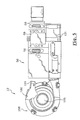
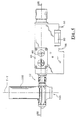
- les figures 4 à 8 représentent les différentes vues extérieures la source de gaz sous pression assemblée avec le bloc de distribution du flux de gaz sous pression, cet ensemble étant illustré respectivement en vue de face, en vue de dessus, en vue de dessous et en vues de côté ;
- la figure 9 est une vue en coupe de la source de gaz sous pression et du bloc de distribution du flux de gaz, selon la ligne 9-9 de la figure 4 ;
- la figure 10 est une vue en coupe partielle de la source de gaz sous pression et du bloc de distribution du flux de gaz selon la ligne 10-10 de la figure 6 ;
- la figure 11 est une vue schématique développée du boisseau rotatif de la valve inspiratoire du bloc de distribution ;
- la figure 12 est une vue partielle en détail de celle représentée à la figure 9, la valve inspiratoire étant dans une position fermée ;
- la figure 13 est une vue similaire à celle représentée à la figure précédente, la valve d'inspiration étant dans une position partiellement ouverte ;
- la figure 14 est une vue similaire à celle représentée à la figure 2, l'appareil d'aide à la ventilation étant équipé d'un circuit simple ;
- la figure 15 est une vue similaire à celle représentée à la figure 2, l'appareil d'aide à la ventilation étant équipé d'un circuit double.
Claims (26)
- Appareil d'aide à la ventilation (10) d'un patient qui respire par des cycles successifs dont chacun comporte une phase inspiratoire et une phase expiratoire, du type qui comporte :caractérisé en ce que la valve inspiratoire (54) de régulation du flux de gaz comporte un corps (62) de valve tubulaire comportant, dans sa paroi, une ouverture oblongue longitudinale (66) qui permet la transmission du flux de gaz depuis l'orifice de sortie (107) de la source de gaz (12) à la première extrémité libre de la conduite principale inspiratoire (14) et comporte, un boisseau (72) qui est monté mobile en rotation dans le corps (62), qui est fermé à l'une de ses extrémités axiales et dont un bord d'extrémité axiale (80) opposé à son extrémité fermée comporte un profil en forme de spirale (86) de façon à provoquer, lors de la rotation du boisseau (72), la variation progressive de la section de passage de l'ouverture oblongue (66) permettant la transmission du flux de gaz.une source de gaz (12) sous pression dont un orifice de sortie fournit un flux de gaz sous pression destiné à être transmis aux voies aériennes supérieures du patient ;un bloc de distribution (50) du flux de gaz sous pression qui comprend un circuit de transmission (52) qui relie l'orifice de sortie (107) de la source de gaz (12) à une première extrémité libre (54) d'une conduite principale inspiratoire (14) sur la seconde extrémité libre de laquelle est fixé un masque (15), notamment du type facial, destiné à être porté par le patient ; etune valve inspiratoire (54) de régulation dudit flux de gaz qui est interposée dans le circuit de transmission (52), qui est commandée par un circuit de commande de l'appareil 10, en fonction notamment des valeurs du débit et de la pression du gaz dans la conduite principale (14), et qui est réalisée sous la forme d'un distributeur rotatif,
- Appareil d'aide à la ventilation (10) selon la revendication précédente, caractérisé en ce que l'orifice de sortie (107) de la source de gaz (12) débouche dans la première extrémité libre d'un premier trou (64) dont la seconde extrémité libre est obturée par l'extrémité fermée du boisseau (72), et en ce que le bloc de distribution (50) comporte un évidement (68) qui débouche d'une part en vis-à-vis de l'ouverture oblongue longitudinale (66) de laquelle il est complémentaire et, d'autre part, dans un deuxième trou (70) borgne sur l'extrémité libre duquel est fixée la première extrémité libre de la conduite principale inspiratoire (14).
- Appareil d'aide à la ventilation (10) selon l'une des revendications 1 ou 2, caractérisé en ce que le boisseau (72) est entraíné en rotation par un moteur (94), notamment du type pas à pas, commandé par le circuit de commande de l'appareil (10).
- Appareil d'aide à la ventilation (10) selon l'une quelconque des revendications précédentes, caractérisé en ce que le boisseau (72) comporte un dispositif d'indexation (96) de sa position angulaire.
- Appareil d'aide à la ventilation (10) selon l'une quelconque des revendications précédentes, caractérisé en ce que le circuit de commande de l'appareil (10) commande la position angulaire du boisseau (72) et la pression fournie par la source de gaz (12) de façon que la section de passage permette la transmission au patient du volume de gaz prédéterminé.
- Appareil d'aide à la ventilation (10) selon l'une quelconque des revendications précédentes, caractérisé en ce que le circuit de commande de l'appareil (10) commande la position angulaire du boisseau (72) de façon que la section de passage corresponde à la totalité de l'ouverture oblongue (66) et, en ce que le circuit de commande de l'appareil (10) commande la pression fournie par la source de gaz (12), pour que la pression du gaz dans la conduite inspiratoire (14) soit la pression de gaz prédéterminée.
- Appareil d'aide à la ventilation (10) selon la revendication précédente, caractérisé que le circuit de commande de l'appareil (10) commande l'oscillation de la position angulaire du boisseau (72) autour d'une position prédéterminée correspondant au débit prédéterminé et commande la pression fournie par la source de gaz (12).
- Appareil d'aide à la ventilation (10) selon l'une quelconque des revendications précédentes, caractérisé en ce que la source de gaz (12) sous pression comporte une machine électrique tournante (100), pilotée en vitesse par le circuit de commande, dont une extrémité libre du rotor (102) entraíne en rotation une roue à aubes (104) qui entraíne le flux gazeux dans une volute de guidage (106) d'un carter (108), lorsque la machine électrique tournante (100) est alimentée électriquement.
- Appareil d'aide à la ventilation (10) selon la revendication précédente, caractérisé en ce que le carter (108) comporte au moins un point d'injection (110), débouchant dans la volute (106), d'au moins un gaz comprimé qui est fourni par une autre source de pression amont, sous une seconde pression supérieure à la première pression, et en ce que le gaz comprimé sous la seconde pression est susceptible d'entraíner en rotation la roue à aubes (104) ainsi que le rotor de la machine électrique tournante (100), de façon que le gaz sous pression soit fourni au patient sous la première pression et que la machine électrique tournante (100) fonctionne en génératrice d'énergie électrique et produise de l'énergie électrique.
- Appareil d'aide à la ventilation (10) selon la revendication précédente, caractérisé en ce que le flux d'au moins un gaz sous une seconde pression est injecté dans le carter (108) selon une direction sensiblement tangentielle à la volute (106).
- Appareil d'aide à la ventilation (10) selon l'une des revendications 9 ou 10, caractérisé que la source de pression amont consiste au moins partiellement en un circuit de gaz sous pression, disponible en milieu hospitalier.
- Appareil d'aide à la ventilation (10) selon l'une quelconque des revendications 9 à 11, caractérisé en ce que la source de pression comporte un réservoir de gaz sous pression.
- Appareil d'aide à la ventilation (10) respiratoire selon la revendication précédente, caractérisé en ce que le réservoir est intégré à l'appareil d'aide à la ventilation (10).
- Appareil d'aide à la ventilation (10) respiratoire selon l'une quelconque des revendications 9 à 13, caractérisé en ce que le gaz sous la seconde pression est composé au moins partiellement d'air.
- Appareil d'aide à la ventilation (10) respiratoire selon l'une quelconque des revendications 9 à 14, caractérisé en ce que le gaz comprimé sous la seconde pression est composé au moins partiellement d'un gaz thérapeutique.
- Appareil d'aide à la ventilation (10) selon la revendication précédente, caractérisé en ce que le gaz thérapeutique est de l'oxygène.
- Appareil d'aide à la ventilation (10) selon l'une quelconque des revendications 9 à 16, caractérisé en ce que des moyens de régulation de pression sont interposés entre ladite autre source de pression amont et le point d'injection (110).
- Appareil d'aide à la ventilation (10) selon l'une quelconque des revendications 9 à 17, caractérisé en ce qu'il comporte une valve de dosage du gaz comprimé sous la seconde pression, dont l'ouverture est commandée de façon proportionnelle à l'ouverture de la valve inspiratoire (54).
- Appareil d'aide à la ventilation (10) respiratoire selon l'une quelconque des revendications 8 à 18, caractérisé en ce que l'énergie électrique fournie par la machine électrique tournante (100), fonctionnant en génératrice, alimente au moins partiellement les systèmes consommateurs d'électricité de l'appareil (10).
- Appareil d'aide à la ventilation (10) respiratoire selon l'une quelconque des revendications 9 à 19, caractérisé en ce que l'énergie électrique produite par la machine électrique tournante (100), fonctionnant en génératrice, alimente et charge au moins partiellement une batterie d'accumulateurs de l'appareil (10).
- Appareil d'aide à la ventilation (10) respiratoire selon l'une quelconque des revendications 9 à 20, caractérisé en ce que l'énergie électrique produite par la machine électrique tournante (100) est supérieure à l'énergie électrique consommée par les systèmes consommateurs d'électricité, de façon que l'appareil d'aide à la ventilation (10) respiratoire soit autonome.
- Appareil d'aide à la ventilation (10) respiratoire selon l'une quelconque des revendications précédentes, caractérisé en ce que le bloc de distribution (50) comporte des moyens de pilotage (122) qui permettent de piloter l'ouverture et la fermeture d'une valve expiratoire (120) qui est agencée indifféremment dans la conduite inspiratoire (14) d'un circuit simple (118) ou dans la conduite expiratoire (130) d'un circuit double (132).
- Appareil d'aide à la ventilation (10) selon la revendication précédente, caractérisé en ce que, lorsque qu'il comporte un circuit double (132), la vanne expiratoire (120) est agencée dans un module (134) qui est fixé sur le bloc de distribution (50) et qui comporte un conduit (124) de façon à relier les moyens de pilotage (122) à la vanne expiratoire (120).
- Appareil d'aide à la ventilation (10) selon l'une des revendications 22 ou 23, caractérisé en ce que les moyens de pilotage (122) permettent d'appliquer à la valve expiratoire (120) une pression expiratoire positive, et en ce que la pression expiratoire positive est fournie par un ventilateur.
- Appareil d'aide à la ventilation (10) selon l'une quelconque des revendications précédentes, caractérisé en ce que le bloc de distribution (50) comporte des moyens de mesure (126) qui déterminent le débit du gaz qui circule, lors de la phase expiratoire, dans la conduite inspiratoire (14) d'un circuit simple (118), ou dans la conduite expiratoire (130) d'un circuit double (132).
- Appareil d'aide à la ventilation (10) selon la revendication précédente, caractérisé en ce que, lorsque qu'il comporte un circuit double (132), il comprend un module (134) qui est fixé sur le bloc de distribution (50) et qui comporte au moins un conduit (129) qui relie les moyens de mesure (126) à la conduite expiratoire (130).
Applications Claiming Priority (2)
| Application Number | Priority Date | Filing Date | Title |
|---|---|---|---|
| FR0010036A FR2812203B1 (fr) | 2000-07-31 | 2000-07-31 | Appareil d'aide a la ventilation d'un patient |
| FR0010036 | 2000-07-31 |
Publications (2)
| Publication Number | Publication Date |
|---|---|
| EP1177810A1 EP1177810A1 (fr) | 2002-02-06 |
| EP1177810B1 true EP1177810B1 (fr) | 2004-03-24 |
Family
ID=8853108
Family Applications (1)
| Application Number | Title | Priority Date | Filing Date |
|---|---|---|---|
| EP01402065A Expired - Lifetime EP1177810B1 (fr) | 2000-07-31 | 2001-07-31 | Appareil d'aide à la ventilation d'un patient |
Country Status (6)
| Country | Link |
|---|---|
| US (1) | US6722359B2 (fr) |
| EP (1) | EP1177810B1 (fr) |
| JP (1) | JP4689893B2 (fr) |
| DE (1) | DE60102422T2 (fr) |
| ES (1) | ES2215865T3 (fr) |
| FR (1) | FR2812203B1 (fr) |
Cited By (2)
| Publication number | Priority date | Publication date | Assignee | Title |
|---|---|---|---|---|
| US8695599B2 (en) | 2007-02-05 | 2014-04-15 | Imtmedical Ag | Control valve for respiratory devices |
| US20220226599A1 (en) * | 2021-01-21 | 2022-07-21 | Drägerwerk AG & Co. KGaA | Valve assembly, ventilator, process for operating a valve assembly, and computer program |
Families Citing this family (64)
| Publication number | Priority date | Publication date | Assignee | Title |
|---|---|---|---|---|
| US7438073B2 (en) * | 2002-03-08 | 2008-10-21 | Kaerys S.A. | Air assistance apparatus for computing the airflow provided by only means of pressure sensors |
| WO2003075990A2 (fr) * | 2002-03-08 | 2003-09-18 | Kaerys S.A. | Appareil d'aide respiratoire destine a calculer le debit d'air fourni uniquement au moyen de capteurs de pression |
| US7448383B2 (en) * | 2002-03-08 | 2008-11-11 | Kaerys, S.A. | Air assistance apparatus providing fast rise and fall of pressure within one patient's breath |
| DE10244795A1 (de) * | 2002-09-26 | 2004-04-08 | Boehringer Ingelheim Pharma Gmbh & Co. Kg | Pulverinhalator |
| FR2852852A1 (fr) * | 2003-03-24 | 2004-10-01 | Saime Sarl | Dispositif d'aide a la respiration |
| FR2852853B1 (fr) * | 2003-03-24 | 2006-12-29 | Saime Sarl | Dispositif d'aide a la respiration |
| EP1610851B1 (fr) * | 2003-03-24 | 2016-11-30 | ResMed Paris SAS | Appareil d'assistance a la respiration |
| US7114497B2 (en) * | 2003-07-18 | 2006-10-03 | Acoba, Llc | Method and system of individually controlling airway pressure of a patient's nares |
| FR2858236B1 (fr) * | 2003-07-29 | 2006-04-28 | Airox | Dispositif et procede de fourniture de gaz respiratoire en pression ou en volume |
| US7044129B1 (en) * | 2003-09-03 | 2006-05-16 | Ric Investments, Llc. | Pressure support system and method |
| DE102005040442A1 (de) * | 2005-08-26 | 2007-03-01 | Weinmann Geräte für Medizin GmbH & Co. KG | Verfahren und Vorrichtung zur Erzeugung von modulierten Druckverläufen |
| FR2889812B1 (fr) * | 2006-09-29 | 2010-10-08 | Saime Sarl | Dispositif d'aide a la respiration |
| WO2008077003A1 (fr) * | 2006-12-19 | 2008-06-26 | Acoba, L.L.C. | Dispositif de pression des voies aériennes positive à soufflante unique et procédé apparenté |
| US8915247B2 (en) * | 2007-02-20 | 2014-12-23 | Resmed Paris | Gas supply unit for a respiratory system |
| US20090071478A1 (en) * | 2007-09-17 | 2009-03-19 | General Electric Company | Ventilator |
| US8457706B2 (en) * | 2008-05-16 | 2013-06-04 | Covidien Lp | Estimation of a physiological parameter using a neural network |
| DE102008036215B4 (de) * | 2008-08-02 | 2010-09-02 | Dae Systems Gmbh | Vorrichtung zur Steuerung des Drucks und/oder Volumenstroms eines Fluids |
| US8302602B2 (en) | 2008-09-30 | 2012-11-06 | Nellcor Puritan Bennett Llc | Breathing assistance system with multiple pressure sensors |
| BRPI0917622A2 (pt) * | 2008-12-11 | 2019-09-24 | Koninklijke Philips Electrnics N. V. | sistema configurado para distribuir o fluxo pressurizado de gás ás vias vias respiratórias de um paciente e um metodo para prover um fluxo pressurizado de gás as vias respiratórias de um paciente |
| US8434479B2 (en) | 2009-02-27 | 2013-05-07 | Covidien Lp | Flow rate compensation for transient thermal response of hot-wire anemometers |
| US20130104883A1 (en) * | 2009-10-20 | 2013-05-02 | Deshum Medical, Llc | Continuous positive airway pressure (cpap) apparauts with orientation sensor |
| US8469031B2 (en) | 2009-12-01 | 2013-06-25 | Covidien Lp | Exhalation valve assembly with integrated filter |
| US8439036B2 (en) | 2009-12-01 | 2013-05-14 | Covidien Lp | Exhalation valve assembly with integral flow sensor |
| US8439037B2 (en) * | 2009-12-01 | 2013-05-14 | Covidien Lp | Exhalation valve assembly with integrated filter and flow sensor |
| US8469030B2 (en) | 2009-12-01 | 2013-06-25 | Covidien Lp | Exhalation valve assembly with selectable contagious/non-contagious latch |
| WO2011116428A1 (fr) | 2010-03-25 | 2011-09-29 | Resmed Paris Sas | Dispositif de commande d'admission de gaz respirable pour appareil de traitement respiratoire |
| EP2368592B1 (fr) * | 2010-03-26 | 2013-04-24 | Dräger Medical GmbH | Valve combinée pour ventilateur commandé par soufflante |
| USD655405S1 (en) | 2010-04-27 | 2012-03-06 | Nellcor Puritan Bennett Llc | Filter and valve body for an exhalation module |
| USD653749S1 (en) | 2010-04-27 | 2012-02-07 | Nellcor Puritan Bennett Llc | Exhalation module filter body |
| USD655809S1 (en) | 2010-04-27 | 2012-03-13 | Nellcor Puritan Bennett Llc | Valve body with integral flow meter for an exhalation module |
| EP2686590B1 (fr) * | 2011-02-15 | 2020-04-01 | Origin Medical Devices Inc. | Système de ventilation médicale avec soupape rotative à orifice variable pour la régulation d'un écoulement de gaz |
| US9629971B2 (en) | 2011-04-29 | 2017-04-25 | Covidien Lp | Methods and systems for exhalation control and trajectory optimization |
| WO2013009193A1 (fr) | 2011-07-13 | 2013-01-17 | Fisher & Paykel Healthcare Limited | Ensemble rotor et moteur |
| US10137264B2 (en) | 2011-07-13 | 2018-11-27 | Fisher & Paykel Healthcare Limited | Respiratory assistance apparatus |
| US10029058B2 (en) | 2011-09-13 | 2018-07-24 | Resmed Limited | Vent arrangement for respiratory mask |
| US9364624B2 (en) | 2011-12-07 | 2016-06-14 | Covidien Lp | Methods and systems for adaptive base flow |
| US9498589B2 (en) | 2011-12-31 | 2016-11-22 | Covidien Lp | Methods and systems for adaptive base flow and leak compensation |
| EP2827929B1 (fr) * | 2012-03-21 | 2021-05-12 | Koninklijke Philips N.V. | Génération d'écoulement bidirectionnel dans un système d'insufflation/exsufflation |
| US9144658B2 (en) | 2012-04-30 | 2015-09-29 | Covidien Lp | Minimizing imposed expiratory resistance of mechanical ventilator by optimizing exhalation valve control |
| US10076619B2 (en) | 2012-09-11 | 2018-09-18 | Resmed Limited | Vent arrangement for respiratory mask |
| DE212013000256U1 (de) | 2012-12-18 | 2015-07-22 | Fisher & Paykel Healthcare Ltd. | Impeller und Rotor Baugruppe |
| USD731049S1 (en) | 2013-03-05 | 2015-06-02 | Covidien Lp | EVQ housing of an exhalation module |
| USD731065S1 (en) | 2013-03-08 | 2015-06-02 | Covidien Lp | EVQ pressure sensor filter of an exhalation module |
| USD693001S1 (en) | 2013-03-08 | 2013-11-05 | Covidien Lp | Neonate expiratory filter assembly of an exhalation module |
| USD744095S1 (en) | 2013-03-08 | 2015-11-24 | Covidien Lp | Exhalation module EVQ internal flow sensor |
| USD692556S1 (en) | 2013-03-08 | 2013-10-29 | Covidien Lp | Expiratory filter body of an exhalation module |
| USD731048S1 (en) | 2013-03-08 | 2015-06-02 | Covidien Lp | EVQ diaphragm of an exhalation module |
| USD736905S1 (en) | 2013-03-08 | 2015-08-18 | Covidien Lp | Exhalation module EVQ housing |
| USD701601S1 (en) | 2013-03-08 | 2014-03-25 | Covidien Lp | Condensate vial of an exhalation module |
| US10328222B2 (en) | 2013-03-14 | 2019-06-25 | ResMed Pty Ltd | Vent device for use with a respiratory device |
| NZ777422A (en) | 2013-03-14 | 2023-01-27 | ResMed Pty Ltd | Vent arrangement for a respiratory device |
| US9950135B2 (en) | 2013-03-15 | 2018-04-24 | Covidien Lp | Maintaining an exhalation valve sensor assembly |
| CN104874064B (zh) * | 2014-02-28 | 2018-07-06 | 北京谊安医疗系统股份有限公司 | 呼吸机自动生产线周转装置 |
| US11147939B2 (en) | 2014-03-11 | 2021-10-19 | Koninklijke Philips N.V. | Compact dual limb diaphragm valve system and method |
| CN103933648B (zh) | 2014-03-26 | 2016-09-07 | 北京雅果科技有限公司 | 一种膈肌刺激吸排气系统 |
| USD775345S1 (en) | 2015-04-10 | 2016-12-27 | Covidien Lp | Ventilator console |
| CN106267511A (zh) * | 2015-06-26 | 2017-01-04 | 北京谊安医疗系统股份有限公司 | 一种主动式电控呼气阀 |
| CN109069778B (zh) * | 2016-02-29 | 2022-06-10 | 伊诺维科技医疗解决方案有限公司 | 便携式轻型呼吸机系统 |
| JP7114569B2 (ja) * | 2016-08-16 | 2022-08-08 | フィッシャー アンド ペイケル ヘルスケア リミテッド | 圧力調整弁 |
| CN114288512B (zh) | 2017-04-23 | 2024-12-13 | 费雪派克医疗保健有限公司 | 呼吸辅助设备 |
| US11896767B2 (en) | 2020-03-20 | 2024-02-13 | Covidien Lp | Model-driven system integration in medical ventilators |
| EP4452375A4 (fr) | 2021-12-21 | 2025-11-26 | Nanotronics Health Llc | Procédé et système de traitement à deux niveaux de l'apnée du sommeil |
| US12036363B2 (en) | 2022-04-22 | 2024-07-16 | Nanotronics Health, LLC. | Respiratory pattern analysis during variable positive air pressure delivery for spontaneously breathing patients |
| EP4494684A1 (fr) * | 2023-07-18 | 2025-01-22 | Sensirion AG | Dispositif et procédé de surveillance d'un écoulement d'un fluide |
Family Cites Families (7)
| Publication number | Priority date | Publication date | Assignee | Title |
|---|---|---|---|---|
| US3972327A (en) * | 1973-03-22 | 1976-08-03 | Hoffmann-La Roche Inc. | Respirator |
| GB2198812B (en) * | 1986-10-20 | 1990-05-16 | Perfection Corp | Angle valve |
| IT1264143B1 (it) * | 1993-04-19 | 1996-09-16 | Dar Spa | Valvola regolatrice di pressione per circuiti per la somministrazione manuale di miscele gassose in ambito medicale |
| US5370112A (en) * | 1993-07-01 | 1994-12-06 | Devilbiss Health Care, Inc. | Method and means for powering portable oxygen supply systems |
| FR2714837B1 (fr) | 1994-01-12 | 1996-09-06 | Saime | Appareil d'aide à la ventilation d'un patient comportant notamment un mode d'assistance inspiratoire volumétrique. |
| ATE252403T1 (de) * | 1994-10-14 | 2003-11-15 | Bird Products Corp | Ausatmungsventil |
| AUPN538495A0 (en) * | 1995-09-12 | 1995-10-05 | Esnouf, Philip Stuart | Disposable oxygenating device |
-
2000
- 2000-07-31 FR FR0010036A patent/FR2812203B1/fr not_active Expired - Lifetime
-
2001
- 2001-07-27 JP JP2001227185A patent/JP4689893B2/ja not_active Expired - Fee Related
- 2001-07-31 US US09/917,898 patent/US6722359B2/en not_active Expired - Lifetime
- 2001-07-31 DE DE60102422T patent/DE60102422T2/de not_active Expired - Lifetime
- 2001-07-31 ES ES01402065T patent/ES2215865T3/es not_active Expired - Lifetime
- 2001-07-31 EP EP01402065A patent/EP1177810B1/fr not_active Expired - Lifetime
Cited By (2)
| Publication number | Priority date | Publication date | Assignee | Title |
|---|---|---|---|---|
| US8695599B2 (en) | 2007-02-05 | 2014-04-15 | Imtmedical Ag | Control valve for respiratory devices |
| US20220226599A1 (en) * | 2021-01-21 | 2022-07-21 | Drägerwerk AG & Co. KGaA | Valve assembly, ventilator, process for operating a valve assembly, and computer program |
Also Published As
| Publication number | Publication date |
|---|---|
| US20020014239A1 (en) | 2002-02-07 |
| FR2812203A1 (fr) | 2002-02-01 |
| ES2215865T3 (es) | 2004-10-16 |
| DE60102422T2 (de) | 2005-05-04 |
| JP2002119595A (ja) | 2002-04-23 |
| FR2812203B1 (fr) | 2003-01-03 |
| DE60102422D1 (de) | 2004-04-29 |
| EP1177810A1 (fr) | 2002-02-06 |
| JP4689893B2 (ja) | 2011-05-25 |
| US6722359B2 (en) | 2004-04-20 |
Similar Documents
| Publication | Publication Date | Title |
|---|---|---|
| EP1177810A1 (fr) | Appareil d'aide à la ventilation d'un patient | |
| EP0862922A1 (fr) | Appareil d'assistance respiratoire muni d'un dispositif pour créer une dépression dans le circuit expiratoire | |
| US6708690B1 (en) | Apparatus and method for providing high frequency variable pressure to a patient | |
| EP1502619B1 (fr) | Dispositif de fourniture de gaz respiratoire en pression ou en volume | |
| ES2367351T3 (es) | Válvula de espiración para ventilador mecánico. | |
| US5931163A (en) | Valve for setting the flow of a flow medium | |
| ES2940361T3 (es) | Sistema de ventilador liviano portátil | |
| FR2856930A1 (fr) | Dispositif d'aide a la respiration a turbine et capteur modulaires. | |
| FR2663547A1 (fr) | Installation de fourniture en continu de surpression de gaz respiratoire. | |
| FR2459053A1 (fr) | Respirateur | |
| FR2852853A1 (fr) | Dispositif d'aide a la respiration | |
| FR2611344A1 (fr) | Appareil respiratoire a circuit ferme | |
| CN101652154A (zh) | 用于呼吸器的控制阀 | |
| EP1293225A3 (fr) | Inhalateur à poudre sèche | |
| EP3622991A1 (fr) | Appareil d'assistance à la toux à valves pneumatiques commandées | |
| WO2010128250A1 (fr) | Dispositif d'assistance à la phonation pour un patient trachéotomisé | |
| EP0236208B1 (fr) | Appareil respiratoire à air comprimé pour la plongée sous-marine | |
| EP4039302A1 (fr) | Appareil de fourniture de gaz thérapeutique à un patient avec contrôle de la pression au masque | |
| EP4052748B1 (fr) | Interface de ventilation de patient destinée à être couplée à un ventilateur médical et à une source de gaz | |
| EP3981454B1 (fr) | Appareil et installation de fourniture de gaz thérapeutique à un patient avec contrôle du débit | |
| FR2784587A1 (fr) | Appareil d'assistance respiratoire comportant des moyens perfectionnes de commande d'une valve d'expiration | |
| WO2021198738A1 (fr) | Recycleur | |
| FR2714837A1 (fr) | Appareil d'aide à la ventilation d'un patient comportant notamment un mode d'assistance inspiratoire volumétrique. | |
| FR2834467A1 (fr) | Valve a demande utilisable en oxygenotherapie | |
| FR2732607A1 (fr) | Appareil d'assistance respiratoire volumetrique muni d'un bloc-soupapes perfectionne |
Legal Events
| Date | Code | Title | Description |
|---|---|---|---|
| PUAI | Public reference made under article 153(3) epc to a published international application that has entered the european phase |
Free format text: ORIGINAL CODE: 0009012 |
|
| AK | Designated contracting states |
Kind code of ref document: A1 Designated state(s): DE ES GB IT Kind code of ref document: A1 Designated state(s): AT BE CH CY DE DK ES FI FR GB GR IE IT LI LU MC NL PT SE TR |
|
| AX | Request for extension of the european patent |
Free format text: AL;LT;LV;MK;RO;SI |
|
| 17P | Request for examination filed |
Effective date: 20020425 |
|
| AKX | Designation fees paid |
Free format text: DE ES GB IT |
|
| 17Q | First examination report despatched |
Effective date: 20020912 |
|
| GRAP | Despatch of communication of intention to grant a patent |
Free format text: ORIGINAL CODE: EPIDOSNIGR1 |
|
| GRAS | Grant fee paid |
Free format text: ORIGINAL CODE: EPIDOSNIGR3 |
|
| GRAA | (expected) grant |
Free format text: ORIGINAL CODE: 0009210 |
|
| AK | Designated contracting states |
Kind code of ref document: B1 Designated state(s): DE ES GB IT |
|
| REG | Reference to a national code |
Ref country code: GB Ref legal event code: FG4D Free format text: NOT ENGLISH |
|
| REG | Reference to a national code |
Ref country code: IE Ref legal event code: FG4D Free format text: FRENCH |
|
| REF | Corresponds to: |
Ref document number: 60102422 Country of ref document: DE Date of ref document: 20040429 Kind code of ref document: P |
|
| GBT | Gb: translation of ep patent filed (gb section 77(6)(a)/1977) |
Effective date: 20040624 |
|
| REG | Reference to a national code |
Ref country code: ES Ref legal event code: FG2A Ref document number: 2215865 Country of ref document: ES Kind code of ref document: T3 |
|
| REG | Reference to a national code |
Ref country code: IE Ref legal event code: FD4D |
|
| PLBE | No opposition filed within time limit |
Free format text: ORIGINAL CODE: 0009261 |
|
| STAA | Information on the status of an ep patent application or granted ep patent |
Free format text: STATUS: NO OPPOSITION FILED WITHIN TIME LIMIT |
|
| 26N | No opposition filed |
Effective date: 20041228 |
|
| REG | Reference to a national code |
Ref country code: GB Ref legal event code: 732E Free format text: REGISTERED BETWEEN 20090319 AND 20090325 |
|
| REG | Reference to a national code |
Ref country code: ES Ref legal event code: PC2A |
|
| REG | Reference to a national code |
Ref country code: DE Ref legal event code: R081 Ref document number: 60102422 Country of ref document: DE Owner name: RESMED PARIS, FR Free format text: FORMER OWNER: SAIME, SAVIGNY-LE-TEMPLE, FR Effective date: 20120329 Ref country code: DE Ref legal event code: R082 Ref document number: 60102422 Country of ref document: DE Representative=s name: VOSSIUS & PARTNER PATENTANWAELTE RECHTSANWAELT, DE Effective date: 20120329 |
|
| REG | Reference to a national code |
Ref country code: DE Ref legal event code: R082 Ref document number: 60102422 Country of ref document: DE Representative=s name: VOSSIUS & PARTNER PATENTANWAELTE RECHTSANWAELT, DE |
|
| PGFP | Annual fee paid to national office [announced via postgrant information from national office to epo] |
Ref country code: ES Payment date: 20190801 Year of fee payment: 19 |
|
| PGFP | Annual fee paid to national office [announced via postgrant information from national office to epo] |
Ref country code: DE Payment date: 20200722 Year of fee payment: 20 Ref country code: GB Payment date: 20200722 Year of fee payment: 20 |
|
| PGFP | Annual fee paid to national office [announced via postgrant information from national office to epo] |
Ref country code: IT Payment date: 20200610 Year of fee payment: 20 |
|
| REG | Reference to a national code |
Ref country code: DE Ref legal event code: R071 Ref document number: 60102422 Country of ref document: DE |
|
| REG | Reference to a national code |
Ref country code: GB Ref legal event code: PE20 Expiry date: 20210730 |
|
| PG25 | Lapsed in a contracting state [announced via postgrant information from national office to epo] |
Ref country code: GB Free format text: LAPSE BECAUSE OF EXPIRATION OF PROTECTION Effective date: 20210730 |
|
| REG | Reference to a national code |
Ref country code: ES Ref legal event code: FD2A Effective date: 20211207 |
|
| PG25 | Lapsed in a contracting state [announced via postgrant information from national office to epo] |
Ref country code: ES Free format text: LAPSE BECAUSE OF NON-PAYMENT OF DUE FEES Effective date: 20200801 |