EP1177757A2 - A vacuum cleaner - Google Patents
A vacuum cleaner Download PDFInfo
- Publication number
- EP1177757A2 EP1177757A2 EP01120850A EP01120850A EP1177757A2 EP 1177757 A2 EP1177757 A2 EP 1177757A2 EP 01120850 A EP01120850 A EP 01120850A EP 01120850 A EP01120850 A EP 01120850A EP 1177757 A2 EP1177757 A2 EP 1177757A2
- Authority
- EP
- European Patent Office
- Prior art keywords
- motor
- vacuum cleaner
- motor filter
- post
- filter
- Prior art date
- Legal status (The legal status is an assumption and is not a legal conclusion. Google has not performed a legal analysis and makes no representation as to the accuracy of the status listed.)
- Withdrawn
Links
Images


Classifications
-
- A—HUMAN NECESSITIES
- A47—FURNITURE; DOMESTIC ARTICLES OR APPLIANCES; COFFEE MILLS; SPICE MILLS; SUCTION CLEANERS IN GENERAL
- A47L—DOMESTIC WASHING OR CLEANING; SUCTION CLEANERS IN GENERAL
- A47L9/00—Details or accessories of suction cleaners, e.g. mechanical means for controlling the suction or for effecting pulsating action; Storing devices specially adapted to suction cleaners or parts thereof; Carrying-vehicles specially adapted for suction cleaners
- A47L9/10—Filters; Dust separators; Dust removal; Automatic exchange of filters
- A47L9/12—Dry filters
- A47L9/127—Dry filters tube- or sleeve-shaped
-
- A—HUMAN NECESSITIES
- A47—FURNITURE; DOMESTIC ARTICLES OR APPLIANCES; COFFEE MILLS; SPICE MILLS; SUCTION CLEANERS IN GENERAL
- A47L—DOMESTIC WASHING OR CLEANING; SUCTION CLEANERS IN GENERAL
- A47L5/00—Structural features of suction cleaners
- A47L5/12—Structural features of suction cleaners with power-driven air-pumps or air-compressors, e.g. driven by motor vehicle engine vacuum
- A47L5/22—Structural features of suction cleaners with power-driven air-pumps or air-compressors, e.g. driven by motor vehicle engine vacuum with rotary fans
- A47L5/28—Suction cleaners with handles and nozzles fixed on the casings, e.g. wheeled suction cleaners with steering handle
- A47L5/32—Suction cleaners with handles and nozzles fixed on the casings, e.g. wheeled suction cleaners with steering handle with means for connecting a hose
-
- A—HUMAN NECESSITIES
- A47—FURNITURE; DOMESTIC ARTICLES OR APPLIANCES; COFFEE MILLS; SPICE MILLS; SUCTION CLEANERS IN GENERAL
- A47L—DOMESTIC WASHING OR CLEANING; SUCTION CLEANERS IN GENERAL
- A47L9/00—Details or accessories of suction cleaners, e.g. mechanical means for controlling the suction or for effecting pulsating action; Storing devices specially adapted to suction cleaners or parts thereof; Carrying-vehicles specially adapted for suction cleaners
- A47L9/0009—Storing devices ; Supports, stands or holders
-
- A—HUMAN NECESSITIES
- A47—FURNITURE; DOMESTIC ARTICLES OR APPLIANCES; COFFEE MILLS; SPICE MILLS; SUCTION CLEANERS IN GENERAL
- A47L—DOMESTIC WASHING OR CLEANING; SUCTION CLEANERS IN GENERAL
- A47L9/00—Details or accessories of suction cleaners, e.g. mechanical means for controlling the suction or for effecting pulsating action; Storing devices specially adapted to suction cleaners or parts thereof; Carrying-vehicles specially adapted for suction cleaners
- A47L9/0081—Means for exhaust-air diffusion; Means for sound or vibration damping
Definitions
- the invention relates to a vacuum cleaner.
- a vacuum cleaner incorporates a dirty air inlet, separating apparatus for separating dirt and dust from an airflow, a fan and motor for drawing an airflow into the separating apparatus via the dirty air inlet, and an outlet for expelling clean air into the atmosphere.
- a pre-motor filter is arranged in the airflow path upstream of the motor to prevent any dust or debris remaining entrained within the airflow from entering the motor. This reduces the risk of the motor becoming damaged or worn as a result of dirt or dust passing therethrough and also prevents such dirt or dust from being expelled into the atmosphere.
- a post-motor filter is arranged downstream of the motor to prevent any carbon particles dislodged within the motor, for example from the brushes within the motor, from being expelled into the atmosphere with the airflow.
- An example of such an arrangement is shown in EP 0245224A.
- These pre- and post-motor filters are normally simple filters or pleated filters which are positioned such that they are relatively easily accessibly whilst being unobtrusive during normal use of the vacuum cleaner.
- Known vacuum cleaners house the pre- and post-motor filters in cassettes slidably receivable in slots or sockets in the motor casing or within the main casing so that they become visible when the cleaner is opened to allow the separating apparatus to be emptied.
- a disadvantage of the existing pre- and post-motor filters is that they are often relatively small in size, which means that the available filtering surface is relatively small. The filters can therefore become clogged over a period of time, despite the small amount of dust and debris they collect, which can affect the performance of the vacuum cleaner. They therefore require to be cleaned or changed more often than is desirable and this leads to increased costs and/or customer dissatisfaction.
- a further disadvantage is that, because the filters are generally hidden during normal operation of the vacuum cleaner, the user of the vacuum cleaner is often unaware that the pre- or post-motor filter may require changing which frustrates the user of the vacuum cleaner.
- the invention provides a vacuum cleaner as claimed in claim 1.
- Utilising cylindrical filters exposes a significantly larger filtration surface area to the airflow which extends the useful life of each filter.
- the preferable co-axial arrangement of the filters with the airflow passing through the centre of the post-motor filter allows the filters to be conveniently located adjacent one another so that they can be accessed easily, should cleaning or replacement be required.
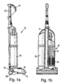
- FIG. 1a and 1b A vacuum cleaner according to the invention is illustrated in Figures 1a and 1b.
- the vacuum cleaner 10 is an upright cleaner having a cleaner head 12 which incorporates a dirty air inlet 14.
- a central support member 16 supports dust separating apparatus 18 on one side thereof and a filter arrangement 20 on the other side thereof.
- An upwardly extending handle 22 is positioned rearwardly of the central support member 16 and is optionally releasable in the manner of a wand if the vacuum cleaner 10 is to be used in the cylinder mode.
- the upwardly extending handle 22 incorporates a hand grip 24 and other features which do not form part of the present invention.
- the cleaner head 12 is pivotably attached to a motor casing 26 to which support wheels 28 are attached and inside which a motor is located. In use, the motor draws dirty air into the vacuum cleaner 10 via the dirty air inlet 14 or alternatively via the wand 22. The air then passes through the dirt and dust separating apparatus 18 and through the filter assembly 20 before being expelled to the atmosphere
- the dirt and dust separating apparatus 18 does not form part of the present invention.
- the separating apparatus 18 can take the form of a bag or other separating means, e.g. cyclonic separating apparatus.
- the dirt and dust separating apparatus 18 will take the form of two concentric cyclones designed to remove dirt and dust particles from the airflow.
- the airflow is fed to the dirt and dust separating apparatus 18 via conduits housed within the central support member 16.
- the airflow Once the airflow has passed through the dirt and dust separating apparatus 18, it is then transferred, via a conduit housed within the central support member 16, to the filter assembly 20.
- the filter assembly 20 is located on the side of the central support member 16 remote from the dirt and dust separating apparatus 18.
- the general shape of the filter assembly 20 will be similar to that of the dirt and dust separating apparatus 18.
- the dirt and dust separating apparatus 18 will be generally cylindrical in shape and the filter assembly 20 will therefore also be cylindrical in shape with substantially the same diameter as that of the dirt and dust separating apparatus 18.
- the filter assembly 20 consists of a pre-motor filter assembly 30 and a post-motor filter assembly 40.
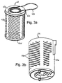
- the pre-motor filter assembly 30 is illustrated in Figures 2a and 2b and the post-motor filter assembly 40 is illustrated in Figures 3a and 3b.
- Each assembly 30,40 consists of a cylindrical filter 32,42 located within a housing 34,44.
- the filtration material is pleated and formed into a cylindrical shape with caps 32a,32a',42a,42a' located at either end to maintain the shape of the filter.
- the pleating of each filter, the support mesh 32b,42b and the fitting of the filtration material into the end caps 32a,32a',42a,42a' are all standard and known in the art. These details will not be described any further here.
- Each housing 34,44 is designed and arranged to hold the respective filter 32,42. Each housing 34,44 is also designed and arranged so as to direct the airflow entering the filter assembly 20 along the correct airflow path.
- the pre-motor filter housing 34 has a generally cylindrical outer wall 34a whose diameter is approximately 10mm larger than the external diameter of the pre-motor filter 32. This allows an annular chamber 34b to be formed between the outer surface of the pre-motor filter 32 and the cylindrical outer wall 34a of the housing 34. The upper end of the outer wall 34a is open to allow the pre-motor filter 32 to be dropped into the housing 34 with ease.
- a collar 34c extending outwardly from the upper end cap 32a centralises the filter 32 when dropped into the housing 34.
- a loop-shaped tab 32d is fixed to the upper end cap 32a to allow the filter 32 to be easily removed from the housing 34 when required.
- a similar collar 42c and tab 42d are fixed to the upper end cap 42a of the post-motor filter 42 for the same reason.
- annular base 34d At the lower end of the pre-motor housing 34 is an annular base 34d having a cylindrical opening in the centre thereof. Upstanding from the annular base 34d are a plurality of upstanding webs 34e on which the lower end of the pre-motor filter 32 is supported. Radial channels are formed between the upstanding webs 34e along which the airflow can pass. A ridge or groove 34f is formed in the annular base 34d around the periphery thereof to receive the post-motor filter housing 44.
- the lower end of the pre-motor filter 32 is closed by means of the cap 32a' extending across the central aperture of the cylindrical filter 32. In this way, air is prevented from passing down the centre of the pre-motor filter 32 beyond the end cap 32a'.
- the post-motor filter housing 44 also consists generally of an outer cylindrical wall 44a.
- the diameter of the outer cylindrical wall 44a is approximately 10mm greater than the outer diameter of the post-motor filter 42. This allows an annular chamber 44c to be created therebetween.
- a plurality of slots 44e are provided in the outer wall 44a and extend around substantially all of the circumference thereof. Bosses 44f are provided on the base of the post-motor filter housing 44 for receiving screws (not shown).
- An inner cylindrical wall 44b forming part of the motor casing of the vacuum cleaner extends upwardly through the centre of the cylindrical post-motor filter 42.
- the upper lip of the inner cylindrical wall 44b is dimensioned and arranged so as to abut against the inner circumference of the annular base 34d of the pre-motor filter housing 34. Sealing means 45 are provided between the upper lip and the annular base 34d.
- the lower end of the inner cylindrical wall 44b is integral with a conduit 46 arranged in the motor casing 26 which leads the airflow through the fan 48 and past the motor 50 before returning it to the post-motor filter 42.
- the diameter of the inner cylindrical wall 44b is approximately 15mm less than the inner diameter of the post-motor filter 42 so that a second annular chamber 44d is created therebetween.
- the second annular chamber 44d communicates with the conduit 46 downstream of the fan 48 and the motor 50. This portion of the conduit 46 is essentially the exhaust side of the motor housing.
- the filter assembly 20 operates in the following manner.
- the airflow enters the pre-motor filter assembly 30 via a conduit 31 which communicates with the interior of the pre-motor filter 32.
- the airflow is forced to pass through the filter 32 in an outwardly radial direction.
- the airflow then enters the annular chamber 34b and passes downwardly to the conduits arranged between the upwardly extending webs 34e.
- the airflow passes radially inwardly between the webs 34e and then passes axially down inside the inner cylindrical wall 44b within the post-motor filter housing 44.
- the airflow thus by-passes the post-motor filter 42 until it has passed along the conduit 46 leading to the fan 48 and the motor 50.
- the airflow passes through the fan 48, around the motor 50, thus having a cooling effect, and then back into the second annular chamber 44d located between the post-motor filter 42 and the inner cylindrical wall 44b. Because the upper end of the post-motor filter 42 is sealed to the top of the inner cylindrical wall 44b, the airflow is forced to pass through the post-motor filter 42. It then passes through the annular chamber 44c and exits the post-motor filter housing 44 via the slots 44e into the atmosphere.
- the conduit 46 and inner cylindrical wall 44b form part of the motor casing 26 of the vacuum cleaner 10 or may take the form of separate parts fixed to or located within the motor casing.
- the fan 48 and the motor 50 are also permanently housed within the motor casing 26.
- the pre-motor filter 32, the post-motor filter 42 and the pre-motor filter housing 34 are all removable from the vacuum cleaner 10.
- the post-motor filter housing 44 is permanently fixed by means of screws, preferably by passing the screws upwardly through bores in the motor casing and into the bosses 44f, into the position shown in Figure 1b.
- the post-motor filer 42 is made accessible by removing the pre-motor filter housing 34 from the vacuum cleaner 10. The post-motor filter 42 can then be removed from the fixed post-motor filter housing 44 via its open upper end.
- a releasable fastening device At the upper end of the filter assembly 20, a releasable fastening device must be employed. Any appropriate releasable fastening means will suffice; for example, a snap-fit arrangement or releasable clip.
- the arrangement illustrated in Figure 4 consists of a rotatable collar 52 which, in its operational position, is biased into a downward position.
- a depending tube 54 having cylindrical walls makes a seal with the inner circumference of the end cap 32a of the pre-motor filter 32 so as to ensure that an airflow entering the filter assembly 20 is directed into the interior of the pre-motor filter 32, and also with the upper lip of the outer cylindrical wall 34a of the pre-motor filter housing 34.
- the tube 54 centralises and maintains the pre-motor filter 32 and the pre-motor filter housing 34 in the appropriate position.
- the ridge or groove 34f at the lower end of the cylindrical wall 34a maintains the desired relative positions of the pre-motor filter housing 34 and the post-motor filter housing 44.
- the collar 52 is designed so as to be rotatable with respect to the body of the vacuum cleaner and also with respect to the pre-motor filter housing 34.
- Cam surfaces (not shown) are provided such that, when the collar 52 is rotated, it is lifted with respect to the pre-motor filter housing 34 so that the tube 54 depending from the collar 52 is raised clear of the filter 32 and the housing 34.
- Biasing means (not shown) are provided in order to bias the collar 52 into its downward position in order to avoid inadvertent raising of the collar 52.
- the biasing means can take the form of a stop detail in the profile of the cam surfaces, resilient plastic strips, deformable foam materials, torsion springs etc.
- the collar 52 is rotated against the action of the biasing means.
- the cylindrical walls of the tube 54 depending from the collar 52 are raised clear of the filter 32 and the cylindrical wall 34a of the housing 34. This allows the housing 34 to be lifted slightly and removed from the post-motor filter housing 44.
- the post-motor filter 42 can be removed from the post-motor filter housing 44 merely by lifting it from the housing 34.
- the pre-motor filter 32 can also be lifted or tipped out of its housing 34. Removing either or both housings 34,44 means that either or both filters 32,42 can be removed or replaced as desired.
- the housings 34, 44 are moulded from transparent plastics materials.
- the transparency of the cylindrical walls 34a,44a of the housings 34,44 allows a user of the vacuum cleaner 10 to inspect the filters 32,42 for signs of clogging.
- the filters 32,42 are visible to the user at all times and the user can therefore readily determine whether or not either or both filters 32,42 require replacement. Because both the pre-motor filter 32 and the post-motor filter 42 are cylindrical filters having large filtration surface areas, it is envisaged that neither filter 32,42 will require replacement very often.
- the slots 44e located in the post-motor filter housing 44 extend around substantially all of the circumference of the housing 44.
- the substantial area through which the airflow is expelled from the vacuum cleaner 10 means that the strength of the exiting airflow is not high.
- the slots are arranged on a curved surface, in this case a cylindrical surface, the airflow is diffused as it leaves the vacuum cleaner. The strength of the airflow is thereby considerably reduced and therefore the problems previously associated with concentrated airflows are avoided.
- the post-motor filter housing can be made releasable from the motor casing if desired.
Abstract
Description
- The invention relates to a vacuum cleaner.
- In general, a vacuum cleaner incorporates a dirty air inlet, separating apparatus for separating dirt and dust from an airflow, a fan and motor for drawing an airflow into the separating apparatus via the dirty air inlet, and an outlet for expelling clean air into the atmosphere. Very often, a pre-motor filter is arranged in the airflow path upstream of the motor to prevent any dust or debris remaining entrained within the airflow from entering the motor. This reduces the risk of the motor becoming damaged or worn as a result of dirt or dust passing therethrough and also prevents such dirt or dust from being expelled into the atmosphere. It is also quite common for a post-motor filter to be arranged downstream of the motor to prevent any carbon particles dislodged within the motor, for example from the brushes within the motor, from being expelled into the atmosphere with the airflow. An example of such an arrangement is shown in EP 0245224A. These pre- and post-motor filters are normally simple filters or pleated filters which are positioned such that they are relatively easily accessibly whilst being unobtrusive during normal use of the vacuum cleaner. Known vacuum cleaners house the pre- and post-motor filters in cassettes slidably receivable in slots or sockets in the motor casing or within the main casing so that they become visible when the cleaner is opened to allow the separating apparatus to be emptied.
- A disadvantage of the existing pre- and post-motor filters is that they are often relatively small in size, which means that the available filtering surface is relatively small. The filters can therefore become clogged over a period of time, despite the small amount of dust and debris they collect, which can affect the performance of the vacuum cleaner. They therefore require to be cleaned or changed more often than is desirable and this leads to increased costs and/or customer dissatisfaction. A further disadvantage is that, because the filters are generally hidden during normal operation of the vacuum cleaner, the user of the vacuum cleaner is often unaware that the pre- or post-motor filter may require changing which frustrates the user of the vacuum cleaner.
- Another disadvantage of known vacuum cleaners relates to the cleaner outlet. Very often, the clean air is expelled to the atmosphere in the form of a stream of air, as is the case in DE U 8607553. In some cases the expelled air is directed in front of the cleaner which can disturb debris which the user intended to pick up with the cleaner. Streams of expelled air can also cause difficulties such as extinguishing pilot lights on gas fires or disturbing curtains, other furnishing or papers lying near the vacuum cleaner. The more powerful the motor of the cleaner, the more likely the expelled air is to cause a disturbance.
- It is an object of the present invention to provide a vacuum cleaner having pre- and post-motor filters which do not require to be cleaned or replaced as frequently as known cleaners. It is a further object to provide a vacuum cleaner having pre- and post-motor filters, in which the fact that one or both of the filters requires cleaning or replacement is more readily apparent to a use of the vacuum cleaner than is currently the case.
- The invention provides a vacuum cleaner as claimed in claim 1. Utilising cylindrical filters exposes a significantly larger filtration surface area to the airflow which extends the useful life of each filter. The preferable co-axial arrangement of the filters with the airflow passing through the centre of the post-motor filter allows the filters to be conveniently located adjacent one another so that they can be accessed easily, should cleaning or replacement be required.
- An embodiment of the invention will now be described with reference to the accompanying drawings, wherein:
- Figures 1a and 1b are side and front views respectively of a vacuum cleaner according to the invention;
- Figures 2a and 2b are isometric views of the pre-motor filter and the pre-motor filter housing respectively, each forming part of the vacuum cleaner of Figures 1a and 1b;
- Figures 3a and 3b are isometric views of the post-motor filter and the post-motor filter housing respectively, each forming part of the vacuum cleaner of Figures 1a and 1b; and
- Figure 4 is a sectional side view of the filters of Figures 2 and 3 illustrated in coaxial arrangement as in use.
-
- A vacuum cleaner according to the invention is illustrated in Figures 1a and 1b. As can readily be seen, the
vacuum cleaner 10 is an upright cleaner having acleaner head 12 which incorporates adirty air inlet 14. Acentral support member 16 supportsdust separating apparatus 18 on one side thereof and afilter arrangement 20 on the other side thereof. An upwardly extendinghandle 22 is positioned rearwardly of thecentral support member 16 and is optionally releasable in the manner of a wand if thevacuum cleaner 10 is to be used in the cylinder mode. The upwardly extendinghandle 22 incorporates ahand grip 24 and other features which do not form part of the present invention. Thecleaner head 12 is pivotably attached to amotor casing 26 to which support wheels 28 are attached and inside which a motor is located. In use, the motor draws dirty air into thevacuum cleaner 10 via thedirty air inlet 14 or alternatively via thewand 22. The air then passes through the dirt anddust separating apparatus 18 and through thefilter assembly 20 before being expelled to the atmosphere. - The dirt and
dust separating apparatus 18 does not form part of the present invention. The separatingapparatus 18 can take the form of a bag or other separating means, e.g. cyclonic separating apparatus. In the example shown, it is envisaged that the dirt anddust separating apparatus 18 will take the form of two concentric cyclones designed to remove dirt and dust particles from the airflow. The airflow is fed to the dirt anddust separating apparatus 18 via conduits housed within thecentral support member 16. - Once the airflow has passed through the dirt and
dust separating apparatus 18, it is then transferred, via a conduit housed within thecentral support member 16, to thefilter assembly 20. Thefilter assembly 20 is located on the side of thecentral support member 16 remote from the dirt anddust separating apparatus 18. - It is envisaged that the general shape of the
filter assembly 20 will be similar to that of the dirt anddust separating apparatus 18. For example, in the embodiment shown, the dirt anddust separating apparatus 18 will be generally cylindrical in shape and thefilter assembly 20 will therefore also be cylindrical in shape with substantially the same diameter as that of the dirt anddust separating apparatus 18. - The
filter assembly 20 consists of apre-motor filter assembly 30 and apost-motor filter assembly 40. Thepre-motor filter assembly 30 is illustrated in Figures 2a and 2b and thepost-motor filter assembly 40 is illustrated in Figures 3a and 3b. Eachassembly cylindrical filter housing cylindrical filter caps support mesh 32b,42b and the fitting of the filtration material into theend caps - Each
housing respective filter housing filter assembly 20 along the correct airflow path. Thepre-motor filter housing 34 has a generally cylindricalouter wall 34a whose diameter is approximately 10mm larger than the external diameter of thepre-motor filter 32. This allows anannular chamber 34b to be formed between the outer surface of thepre-motor filter 32 and the cylindricalouter wall 34a of thehousing 34. The upper end of theouter wall 34a is open to allow thepre-motor filter 32 to be dropped into thehousing 34 with ease. Acollar 34c extending outwardly from theupper end cap 32a centralises thefilter 32 when dropped into thehousing 34. A loop-shaped tab 32d is fixed to theupper end cap 32a to allow thefilter 32 to be easily removed from thehousing 34 when required. Asimilar collar 42c andtab 42d are fixed to theupper end cap 42a of thepost-motor filter 42 for the same reason. - At the lower end of the
pre-motor housing 34 is an annular base 34d having a cylindrical opening in the centre thereof. Upstanding from the annular base 34d are a plurality ofupstanding webs 34e on which the lower end of thepre-motor filter 32 is supported. Radial channels are formed between theupstanding webs 34e along which the airflow can pass. A ridge orgroove 34f is formed in the annular base 34d around the periphery thereof to receive thepost-motor filter housing 44. - The lower end of the
pre-motor filter 32 is closed by means of thecap 32a' extending across the central aperture of thecylindrical filter 32. In this way, air is prevented from passing down the centre of thepre-motor filter 32 beyond theend cap 32a'. - The
post-motor filter housing 44 also consists generally of an outercylindrical wall 44a. The diameter of the outercylindrical wall 44a is approximately 10mm greater than the outer diameter of thepost-motor filter 42. This allows an annular chamber 44c to be created therebetween. A plurality ofslots 44e are provided in theouter wall 44a and extend around substantially all of the circumference thereof. Bosses 44f are provided on the base of thepost-motor filter housing 44 for receiving screws (not shown). - An inner
cylindrical wall 44b forming part of the motor casing of the vacuum cleaner extends upwardly through the centre of the cylindricalpost-motor filter 42. The upper lip of the innercylindrical wall 44b is dimensioned and arranged so as to abut against the inner circumference of the annular base 34d of thepre-motor filter housing 34. Sealing means 45 are provided between the upper lip and the annular base 34d. The lower end of the innercylindrical wall 44b is integral with a conduit 46 arranged in themotor casing 26 which leads the airflow through thefan 48 and past themotor 50 before returning it to thepost-motor filter 42. - The diameter of the inner
cylindrical wall 44b is approximately 15mm less than the inner diameter of thepost-motor filter 42 so that a second annular chamber 44d is created therebetween. The second annular chamber 44d communicates with the conduit 46 downstream of thefan 48 and themotor 50. This portion of the conduit 46 is essentially the exhaust side of the motor housing. - The
filter assembly 20 operates in the following manner. The airflow enters thepre-motor filter assembly 30 via aconduit 31 which communicates with the interior of thepre-motor filter 32. There being no axial escape route due to thecap 32a at the bottom of thefilter 32 extending across the interior of thefilter 32, the airflow is forced to pass through thefilter 32 in an outwardly radial direction. The airflow then enters theannular chamber 34b and passes downwardly to the conduits arranged between the upwardly extendingwebs 34e. The airflow passes radially inwardly between thewebs 34e and then passes axially down inside the innercylindrical wall 44b within thepost-motor filter housing 44. The airflow thus by-passes thepost-motor filter 42 until it has passed along the conduit 46 leading to thefan 48 and themotor 50. The airflow passes through thefan 48, around themotor 50, thus having a cooling effect, and then back into the second annular chamber 44d located between thepost-motor filter 42 and the innercylindrical wall 44b. Because the upper end of thepost-motor filter 42 is sealed to the top of the innercylindrical wall 44b, the airflow is forced to pass through thepost-motor filter 42. It then passes through the annular chamber 44c and exits thepost-motor filter housing 44 via theslots 44e into the atmosphere. - The conduit 46 and inner
cylindrical wall 44b form part of themotor casing 26 of thevacuum cleaner 10 or may take the form of separate parts fixed to or located within the motor casing. Thefan 48 and themotor 50 are also permanently housed within themotor casing 26. However, thepre-motor filter 32, thepost-motor filter 42 and thepre-motor filter housing 34 are all removable from thevacuum cleaner 10. Thepost-motor filter housing 44 is permanently fixed by means of screws, preferably by passing the screws upwardly through bores in the motor casing and into the bosses 44f, into the position shown in Figure 1b. Thepost-motor filer 42 is made accessible by removing thepre-motor filter housing 34 from thevacuum cleaner 10. Thepost-motor filter 42 can then be removed from the fixedpost-motor filter housing 44 via its open upper end. - At the upper end of the
filter assembly 20, a releasable fastening device must be employed. Any appropriate releasable fastening means will suffice; for example, a snap-fit arrangement or releasable clip. The arrangement illustrated in Figure 4 consists of arotatable collar 52 which, in its operational position, is biased into a downward position. A dependingtube 54 having cylindrical walls makes a seal with the inner circumference of theend cap 32a of thepre-motor filter 32 so as to ensure that an airflow entering thefilter assembly 20 is directed into the interior of thepre-motor filter 32, and also with the upper lip of the outercylindrical wall 34a of thepre-motor filter housing 34. Thetube 54 centralises and maintains thepre-motor filter 32 and thepre-motor filter housing 34 in the appropriate position. The ridge orgroove 34f at the lower end of thecylindrical wall 34a maintains the desired relative positions of thepre-motor filter housing 34 and thepost-motor filter housing 44. - The
collar 52 is designed so as to be rotatable with respect to the body of the vacuum cleaner and also with respect to thepre-motor filter housing 34. Cam surfaces (not shown) are provided such that, when thecollar 52 is rotated, it is lifted with respect to thepre-motor filter housing 34 so that thetube 54 depending from thecollar 52 is raised clear of thefilter 32 and thehousing 34. Biasing means (not shown) are provided in order to bias thecollar 52 into its downward position in order to avoid inadvertent raising of thecollar 52. The biasing means can take the form of a stop detail in the profile of the cam surfaces, resilient plastic strips, deformable foam materials, torsion springs etc. - In order to remove the
filter assembly 20 from thevacuum cleaner 10, thecollar 52 is rotated against the action of the biasing means. The cylindrical walls of thetube 54 depending from thecollar 52 are raised clear of thefilter 32 and thecylindrical wall 34a of thehousing 34. This allows thehousing 34 to be lifted slightly and removed from thepost-motor filter housing 44. As soon as thepre-motor filter housing 34 has been removed, thepost-motor filter 42 can be removed from thepost-motor filter housing 44 merely by lifting it from thehousing 34. Thepre-motor filter 32 can also be lifted or tipped out of itshousing 34. Removing either or bothhousings filters - The
housings cylindrical walls housings vacuum cleaner 10 to inspect thefilters pre-motor filter 32 andpost-motor filter 42 be inspected only when thedust separating apparatus 18 are accessed for emptying purposes. Thefilters filters pre-motor filter 32 and thepost-motor filter 42 are cylindrical filters having large filtration surface areas, it is envisaged that neitherfilter - The
slots 44e located in thepost-motor filter housing 44 extend around substantially all of the circumference of thehousing 44. The substantial area through which the airflow is expelled from thevacuum cleaner 10 means that the strength of the exiting airflow is not high. Furthermore, because the slots are arranged on a curved surface, in this case a cylindrical surface, the airflow is diffused as it leaves the vacuum cleaner. The strength of the airflow is thereby considerably reduced and therefore the problems previously associated with concentrated airflows are avoided. - As a further example, the following dimensions are given in order to further enable a skilled reader to the put the invention into practice.
External diameter of filters 10cm Internal diameter of filters 5.2cm Length of filters 14cm Internal diameter of outer cylindrical walls 11cm External diameter of inner cylindrical wall 44b3.7cm - The scope of the invention is not limited to the precise details of the embodiment described above. Modifications and variations will be apparent to a reader skilled in the art. For example, the post-motor filter housing can be made releasable from the motor casing if desired.
Claims (12)
- A vacuum cleaner comprising an airflow path having a dirty air inlet (14) and a clean air outlet (44e), a fan (48) for drawing an airflow along the airflow path from the dirty air inlet (14) to the clean air outlet (44e), a motor (50) for driving the fan (48), separating apparatus (18) for separating dirt and dust from the airflow, a pre-motor filter (32) arranged upstream of the motor (50) and a post-motor filter (42) arranged downstream of the motor (50), characterised in that both the pre-motor filter (32) and the post-motor filter (42) are cylindrical filters
- A vacuum cleaner as claimed in claim 1, wherein the airflow is arranged to flow radially outwardly through each of the filters (32, 42) when the vacuum cleaner is in use.
- A vacuum cleaner as claimed in claim 1 or 2, wherein the pre-motor filter (32) and the post-motor filter (42) are each housed in a transparent casing.
- A vacuum cleaner as claimed in claim 3, wherein the pre-motor filter (32) and the post motor filter (42) are housed in separate transparent casings (34, 44).
- A vacuum cleaner as claimed in claim 4, wherein the cylindrical filters (32, 42) are arranged coaxially and adjacent one another, the airflow path passing through the centre of the post-motor filter (42) between the pre-motor filter (32) and the motor (50).
- A vacuum cleaner as claimed in claim 5, wherein the cylindrical filters (32, 42) are positioned generally upright and parallel to the separating apparatus (18), the upper end of the uppermost casing (34) being held in place by means of a retractable collar (34c).
- A vacuum cleaner as claimed in claim 6, wherein the collar (34c) is biased into a non-retracted position in which the uppermost casing (34) is retained in place.
- A vacuum cleaner as claimed in any one of the preceding claims, wherein the airflow is arranged to pass across or around the motor (50) to provide cooling.
- A vacuum cleaner as claimed in any one of the preceding claims, wherein the separating apparatus (18) comprise at least one cyclone.
- A vacuum cleaner as claimed in claim 9, wherein the separating apparatus (18) comprise two concentric cyclones.
- A vacuum cleaner as claimed in any one of the preceding claims, wherein the pre-motor filter (32) and the post-motor filter (42) are substantially the same size.
- A vacuum cleaner as claimed in claim 11, wherein the pre-motor filter (32) and the post-motor filter (42) have substantially the same characteristics.
Applications Claiming Priority (3)
| Application Number | Priority Date | Filing Date | Title |
|---|---|---|---|
| GBGB9726676.1A GB9726676D0 (en) | 1997-12-17 | 1997-12-17 | A vacuum cleaner |
| GB9726676 | 1997-12-17 | ||
| EP98961318A EP1047331B3 (en) | 1997-12-17 | 1998-12-17 | A vacuum cleaner |
Related Parent Applications (2)
| Application Number | Title | Priority Date | Filing Date |
|---|---|---|---|
| EP98961318A Division EP1047331B3 (en) | 1997-12-17 | 1998-12-17 | A vacuum cleaner |
| EP98961318A Division-Into EP1047331B3 (en) | 1997-12-17 | 1998-12-17 | A vacuum cleaner |
Publications (2)
| Publication Number | Publication Date |
|---|---|
| EP1177757A2 true EP1177757A2 (en) | 2002-02-06 |
| EP1177757A3 EP1177757A3 (en) | 2002-04-17 |
Family
ID=10823773
Family Applications (2)
| Application Number | Title | Priority Date | Filing Date |
|---|---|---|---|
| EP98961318A Expired - Lifetime EP1047331B3 (en) | 1997-12-17 | 1998-12-17 | A vacuum cleaner |
| EP01120850A Withdrawn EP1177757A3 (en) | 1997-12-17 | 1998-12-17 | A vacuum cleaner |
Family Applications Before (1)
| Application Number | Title | Priority Date | Filing Date |
|---|---|---|---|
| EP98961318A Expired - Lifetime EP1047331B3 (en) | 1997-12-17 | 1998-12-17 | A vacuum cleaner |
Country Status (15)
| Country | Link |
|---|---|
| US (1) | US6289553B1 (en) |
| EP (2) | EP1047331B3 (en) |
| JP (1) | JP4156798B2 (en) |
| KR (1) | KR100555862B1 (en) |
| CN (2) | CN1283200C (en) |
| AT (1) | ATE223175T1 (en) |
| AU (1) | AU733940B2 (en) |
| BR (1) | BR9813636A (en) |
| CA (1) | CA2315078C (en) |
| DE (2) | DE69807752D1 (en) |
| ES (1) | ES2183433T7 (en) |
| GB (1) | GB9726676D0 (en) |
| ID (1) | ID26354A (en) |
| TR (2) | TR200101955T2 (en) |
| WO (1) | WO1999030602A2 (en) |
Cited By (5)
| Publication number | Priority date | Publication date | Assignee | Title |
|---|---|---|---|---|
| WO2005051155A1 (en) | 2003-11-28 | 2005-06-09 | Aktiebolaget Electrolux | Vacuum cleaner filtration system |
| KR100539745B1 (en) * | 2003-04-17 | 2006-01-10 | 엘지전자 주식회사 | Air flow apparatus of upright cleaner |
| WO2007104140A1 (en) * | 2006-03-10 | 2007-09-20 | Gbd Corp. | Cyclonic vacuum cleaner |
| EP1629761A3 (en) * | 2004-08-31 | 2007-11-14 | LG Electronics Inc. | Dust collection unit and vacuum cleaner comprising same |
| GB2465780A (en) * | 2008-11-28 | 2010-06-02 | Dyson Technology Ltd | A cleaning appliance |
Families Citing this family (107)
| Publication number | Priority date | Publication date | Assignee | Title |
|---|---|---|---|---|
| GB9726673D0 (en) | 1997-12-17 | 1998-02-18 | Notetry Ltd | A vacuum cleaner |
| US6070291A (en) | 1998-01-09 | 2000-06-06 | Royal Appliance Mfg. Co. | Upright vacuum cleaner with cyclonic air flow |
| WO1999034722A1 (en) | 1998-01-09 | 1999-07-15 | Royal Appliance Mfg. Co. | Upright vacuum cleaner with cyclonic airflow |
| US6558453B2 (en) | 2000-01-14 | 2003-05-06 | White Consolidated Industries, Inc. | Bagless dustcup |
| US6910245B2 (en) | 2000-01-14 | 2005-06-28 | White Consolidated Industries, Inc. | Upright vacuum cleaner with cyclonic air path |
| US20030159411A1 (en) * | 2000-05-05 | 2003-08-28 | Bissell Homecare, Inc. | Cyclonic dirt separation module |
| US6385810B1 (en) | 2000-05-05 | 2002-05-14 | The Hoover Company | Latch arrangement for a vacuum cleaner dirt receptacle |
| KR100345229B1 (en) * | 2000-07-06 | 2002-07-25 | 삼성광주전자 주식회사 | Reflux cleaner |
| US6532621B2 (en) * | 2001-01-12 | 2003-03-18 | Royal Appliance Mfg. Co. | Vacuum cleaner with noise suppression features |
| US7143469B2 (en) | 2001-02-06 | 2006-12-05 | The Hoover Company | Dirt collecting system |
| GB2372431B (en) * | 2001-02-24 | 2004-09-15 | Dyson Ltd | A domestic appliance |
| KR100412586B1 (en) * | 2001-06-01 | 2003-12-31 | 삼성광주전자 주식회사 | Grille assembly for a cyclone-type dust collecting apparatus for a vacuum cleaner |
| GB2391459A (en) | 2002-08-09 | 2004-02-11 | Dyson Ltd | A surface treating appliance with increased manoeuverability |
| US7496988B2 (en) * | 2002-09-25 | 2009-03-03 | Toshiba Tec Kabushiki Kaisha | Electric vacuum cleaner provided with a dust separation section for separating sucked dust and dust collecting section for collecting the dust |
| KR100456167B1 (en) * | 2002-11-22 | 2004-11-09 | 삼성광주전자 주식회사 | Dust collecting filter for vacuum cleaner and vacuum cleaner having the same |
| US20040134022A1 (en) | 2003-01-10 | 2004-07-15 | Royal Manufacturing Co. | Bagless stick type vacuum cleaner |
| KR100500848B1 (en) | 2003-07-07 | 2005-07-12 | 삼성광주전자 주식회사 | Motor assembly and vacuum cleaner having the same |
| US7552506B2 (en) * | 2003-07-09 | 2009-06-30 | Lg Electronics Inc. | Filter assembly for vacuum cleaner |
| DE602005007195D1 (en) * | 2004-03-15 | 2008-07-10 | Koninkl Philips Electronics Nv | SEPARATE ARRANGEMENT FOR A VACUUM CLEANER WITH MULTI-STAGE DUST SEPARATION |
| US7406744B2 (en) * | 2005-01-20 | 2008-08-05 | Marc Bruneau | Central vacuum system with secondary airflow path |
| GB2427999A (en) * | 2005-07-07 | 2007-01-17 | Hoover Ltd | Vacuum cleaner providing filter-absence detection |
| US20070163073A1 (en) * | 2006-01-19 | 2007-07-19 | Arnold Sepke | Vacuum cleaner dustcup and conduit construction |
| US8252096B2 (en) | 2006-06-08 | 2012-08-28 | Dyson Technology Limited | Cleaning and/or filtering apparatus |
| GB2440515B (en) * | 2006-08-01 | 2011-06-15 | Dyson Technology Ltd | A filter assembly |
| GB2440514A (en) * | 2006-08-01 | 2008-02-06 | Dyson Technology Ltd | A filter assembly |
| GB2457420B (en) | 2006-12-12 | 2012-01-04 | Gbd Corp | Convertible surface cleaning apparatus |
| AU2009202180B2 (en) * | 2008-06-05 | 2014-10-23 | Bissell Inc. | Cyclonic vacuum cleaner with improved collection chamber |
| KR101025954B1 (en) | 2008-08-07 | 2011-03-30 | 엘지전자 주식회사 | Vacuunm cleaner |
| US20100199969A1 (en) * | 2009-02-10 | 2010-08-12 | Edmund Chan | Pool protection and solar heating cover |
| KR20100093447A (en) * | 2009-02-16 | 2010-08-25 | 삼성광주전자 주식회사 | Dust collector for vacuum cleaner |
| US9089248B2 (en) * | 2009-02-16 | 2015-07-28 | Samsung Electronics Co., Ltd. | Fan motor apparatus having diffuser unit for vacuum cleaner |
| US9591953B2 (en) | 2009-03-13 | 2017-03-14 | Omachron Intellectual Property Inc. | Surface cleaning apparatus |
| CA2674376A1 (en) | 2009-03-13 | 2010-09-13 | G.B.D. Corp. | Surface cleaning apparatus with different cleaning configurations |
| US9480373B2 (en) | 2009-03-13 | 2016-11-01 | Omachron Intellectual Property Inc. | Surface cleaning apparatus |
| US9427122B2 (en) | 2009-03-13 | 2016-08-30 | Omachron Intellectual Property Inc. | Surface cleaning apparatus |
| US9198551B2 (en) | 2013-02-28 | 2015-12-01 | Omachron Intellectual Property Inc. | Surface cleaning apparatus |
| US11612288B2 (en) | 2009-03-13 | 2023-03-28 | Omachron Intellectual Property Inc. | Surface cleaning apparatus |
| US9226633B2 (en) | 2009-03-13 | 2016-01-05 | Omachron Intellectual Property Inc. | Surface cleaning apparatus |
| US9392916B2 (en) | 2009-03-13 | 2016-07-19 | Omachron Intellectual Property Inc. | Surface cleaning apparatus |
| US10722086B2 (en) | 2017-07-06 | 2020-07-28 | Omachron Intellectual Property Inc. | Handheld surface cleaning apparatus |
| RU2531897C2 (en) | 2009-03-31 | 2014-10-27 | Дайсон Текнолоджи Лимитед | Separating device |
| CN101870197B (en) * | 2009-04-23 | 2014-06-04 | 海德堡印刷机械股份公司 | Washing device |
| KR101566426B1 (en) * | 2009-05-07 | 2015-11-06 | 삼성전자주식회사 | Vacuum cleaner |
| GB2472097B (en) * | 2009-07-24 | 2013-04-17 | Dyson Technology Ltd | Separating apparatus with electrostatic filter |
| GB2474464B (en) | 2009-10-15 | 2013-11-20 | Dyson Technology Ltd | A surface treating appliance |
| GB2474471B (en) | 2009-10-15 | 2013-10-23 | Dyson Technology Ltd | A surface treating appliance |
| GB2474463B (en) | 2009-10-15 | 2013-11-13 | Dyson Technology Ltd | A surface treating appliance |
| GB2474472B (en) | 2009-10-15 | 2013-10-23 | Dyson Technology Ltd | A surface treating appliance |
| GB2474462B (en) | 2009-10-15 | 2013-12-11 | Dyson Technology Ltd | A surface treating appliance with domed-shaped wheels |
| GB2474468B (en) | 2009-10-15 | 2013-11-27 | Dyson Technology Ltd | A surface treating appliance |
| GB2474473B (en) | 2009-10-15 | 2013-10-23 | Dyson Technology Ltd | A surface treating appliance |
| KR101970584B1 (en) * | 2011-09-01 | 2019-08-27 | 삼성전자주식회사 | Cleaning system and maintenance station thereof |
| GB2494442B (en) * | 2011-09-09 | 2013-12-25 | Dyson Technology Ltd | Autonomous vacuum cleaner |
| WO2013131170A1 (en) * | 2012-03-09 | 2013-09-12 | G.B.D. Corp. | Surface cleaning apparatus with openable filter compartment |
| US9492045B2 (en) * | 2012-03-09 | 2016-11-15 | Omachron Intellectual Property Inc. | Filter assembly for a surface cleaning apparatus |
| GB2502131B (en) * | 2012-05-17 | 2014-11-05 | Dyson Technology Ltd | Autonomous vacuum cleaner |
| CN103908195B (en) * | 2013-01-08 | 2017-06-27 | 苏州宝时得电动工具有限公司 | The method for cleaning of vacuum cleaner and its filter |
| US10674884B2 (en) | 2013-02-28 | 2020-06-09 | Omachron Intellectual Property Inc. | Hand carryable surface cleaning apparatus |
| US9215960B2 (en) | 2013-02-28 | 2015-12-22 | Omachron Intellectual Property Inc. | Surface cleaning apparatus |
| US10729294B2 (en) | 2013-02-28 | 2020-08-04 | Omachron Intellectual Property Inc. | Hand carryable surface cleaning apparatus |
| US10791889B2 (en) | 2016-01-08 | 2020-10-06 | Omachron Intellectual Property Inc. | Hand carryable surface cleaning apparatus |
| US11950745B2 (en) | 2014-12-17 | 2024-04-09 | Omachron Intellectual Property Inc. | Surface cleaning apparatus |
| AU2016211669C1 (en) | 2015-01-26 | 2020-05-07 | Hayward Industries, Inc. | Swimming pool cleaner with hydrocyclonic particle separator and/or six-roller drive system |
| US9885196B2 (en) | 2015-01-26 | 2018-02-06 | Hayward Industries, Inc. | Pool cleaner power coupling |
| CN108463151B (en) | 2015-11-10 | 2021-07-23 | 创科实业有限公司 | Hand-held vacuum cleaner |
| US10165914B2 (en) | 2016-01-08 | 2019-01-01 | Omachron Intellectual Property Inc. | Hand carryable surface cleaning apparatus |
| US9962048B2 (en) | 2016-01-08 | 2018-05-08 | Omachron Intellectual Property | Hand carryable surface cleaning apparatus |
| US10085604B2 (en) | 2016-01-08 | 2018-10-02 | Omachron Intellectual Property Inc. | Hand carryable surface cleaning apparatus |
| WO2017171500A1 (en) | 2016-03-31 | 2017-10-05 | 엘지전자 주식회사 | Cleaning apparatus |
| US11166607B2 (en) | 2016-03-31 | 2021-11-09 | Lg Electronics Inc. | Cleaner |
| CN209733830U (en) | 2016-03-31 | 2019-12-06 | Lg电子株式会社 | Vacuum cleaner |
| KR102560970B1 (en) * | 2016-03-31 | 2023-07-31 | 엘지전자 주식회사 | Cleaner |
| US10575689B2 (en) | 2016-03-31 | 2020-03-03 | Lg Electronics Inc. | Cleaner |
| EP4104732B1 (en) | 2016-03-31 | 2023-05-31 | LG Electronics Inc. | Cleaning apparatus |
| US10638903B2 (en) | 2016-03-31 | 2020-05-05 | Lg Electronics Inc. | Cleaner |
| US10646082B2 (en) | 2016-03-31 | 2020-05-12 | Lg Electronics Inc. | Cleaner |
| US9936846B2 (en) | 2016-04-25 | 2018-04-10 | Omachron Intellectual Property Inc. | Cyclone assembly for surface cleaning apparatus and a surface cleaning apparatus having same |
| US10251521B2 (en) | 2016-04-25 | 2019-04-09 | Omachron Intellectual Property Inc. | Cyclone assembly for surface cleaning apparatus and a surface cleaning apparatus having same |
| US10537219B2 (en) | 2016-04-25 | 2020-01-21 | Omachron Intellectual Property Inc. | Cyclone assembly for surface cleaning apparatus and a surface cleaning apparatus having same |
| US10149587B2 (en) | 2016-04-25 | 2018-12-11 | Omachron Intellectual Property Inc. | Cyclone assembly for surface cleaning apparatus and a surface cleaning apparatus having same |
| US10201260B2 (en) | 2016-04-25 | 2019-02-12 | Omachron Intellectual Property Inc. | Cyclone assembly for surface cleaning apparatus and a surface cleaning apparatus having same |
| US10321794B2 (en) * | 2016-08-29 | 2019-06-18 | Omachron Intellectual Property Inc. | Surface cleaning apparatus |
| US10441125B2 (en) * | 2016-08-29 | 2019-10-15 | Omachron Intellectual Property Inc. | Surface cleaning apparatus |
| US10413141B2 (en) | 2016-08-29 | 2019-09-17 | Omachron Intellectual Property Inc. | Surface cleaning apparatus |
| US10441124B2 (en) | 2016-08-29 | 2019-10-15 | Omachron Intellectual Property Inc. | Surface cleaning apparatus |
| US11478117B2 (en) | 2016-08-29 | 2022-10-25 | Omachron Intellectual Property Inc. | Surface cleaning apparatus |
| US9885194B1 (en) | 2017-05-11 | 2018-02-06 | Hayward Industries, Inc. | Pool cleaner impeller subassembly |
| US9896858B1 (en) | 2017-05-11 | 2018-02-20 | Hayward Industries, Inc. | Hydrocyclonic pool cleaner |
| US10156083B2 (en) | 2017-05-11 | 2018-12-18 | Hayward Industries, Inc. | Pool cleaner power coupling |
| US10537216B2 (en) | 2017-07-06 | 2020-01-21 | Omachron Intellectual Property Inc. | Handheld surface cleaning apparatus |
| US10750913B2 (en) | 2017-07-06 | 2020-08-25 | Omachron Intellectual Property Inc. | Handheld surface cleaning apparatus |
| US10506904B2 (en) | 2017-07-06 | 2019-12-17 | Omachron Intellectual Property Inc. | Handheld surface cleaning apparatus |
| US10631693B2 (en) | 2017-07-06 | 2020-04-28 | Omachron Intellectual Property Inc. | Handheld surface cleaning apparatus |
| US10842330B2 (en) | 2017-07-06 | 2020-11-24 | Omachron Intellectual Property Inc. | Handheld surface cleaning apparatus |
| US10702113B2 (en) | 2017-07-06 | 2020-07-07 | Omachron Intellectual Property Inc. | Handheld surface cleaning apparatus |
| GB2591589B (en) * | 2017-12-20 | 2022-08-10 | Dyson Technology Ltd | A filter assembly |
| GB2569569B (en) * | 2017-12-20 | 2021-04-21 | Dyson Technology Ltd | A filter assembly |
| GB2591588B (en) * | 2017-12-20 | 2022-08-10 | Dyson Technology Ltd | A filter assembly |
| US11478116B2 (en) | 2018-01-15 | 2022-10-25 | Omachron Intellectual Property Inc | Surface cleaning apparatus |
| US11013378B2 (en) | 2018-04-20 | 2021-05-25 | Omachon Intellectual Property Inc. | Surface cleaning apparatus |
| US10932634B2 (en) | 2018-05-30 | 2021-03-02 | Omachron Intellectual Property Inc. | Surface cleaning apparatus |
| US10827889B2 (en) | 2018-05-30 | 2020-11-10 | Omachron Intellectual Property Inc. | Surface cleaning apparatus |
| US11154169B2 (en) | 2018-08-13 | 2021-10-26 | Omachron Intellectual Property Inc. | Cyclonic air treatment member and surface cleaning apparatus including the same |
| US10882059B2 (en) | 2018-09-21 | 2021-01-05 | Omachron Intellectual Property Inc. | Multi cyclone array for surface cleaning apparatus and a surface cleaning apparatus having same |
| GB2578873B (en) * | 2018-11-09 | 2021-08-18 | Dyson Technology Ltd | A vacuum cleaner and a filter assembly |
| GB2621467A (en) * | 2022-06-29 | 2024-02-14 | Dyson Technology Ltd | Vacuum cleaner |
| WO2024003809A1 (en) * | 2022-06-29 | 2024-01-04 | Dyson Technology Limited | Vacuum cleaner |
Family Cites Families (19)
| Publication number | Priority date | Publication date | Assignee | Title |
|---|---|---|---|---|
| US2388280A (en) * | 1943-09-27 | 1945-11-06 | Air Way Electric Appl Corp | Suction cleaner |
| US2779432A (en) * | 1953-05-07 | 1957-01-29 | Lewyt Corp | Vacuum cleaner assembly |
| US3046718A (en) * | 1959-04-08 | 1962-07-31 | Kent Company Inc | Suction cleaner |
| US3621640A (en) * | 1968-10-14 | 1971-11-23 | Matsushita Electric Ind Co Ltd | Electric vacuum cleaner |
| US4072483A (en) | 1976-05-20 | 1978-02-07 | Doyle Vacuum Cleaner Company | Vacuum cleaners |
| NL7613475A (en) | 1976-12-03 | 1978-06-06 | Philips Nv | VACUUM CLEANER. |
| DE3220644A1 (en) * | 1982-06-02 | 1983-12-08 | Düpro AG, 8590 Romanshorn | EXTRACTION DEVICE |
| SE434469B (en) | 1982-12-13 | 1984-07-30 | Soederhamn Ind Arbetshygien Ab | STOFTAVSKILJARAGGREGAT |
| GB2137896B (en) | 1983-04-12 | 1987-05-20 | Hoover Plc | Suction cleaner |
| GB2167680A (en) * | 1984-11-30 | 1986-06-04 | Enviro Vac Limited | Environmental cleaning machine |
| DE8607553U1 (en) * | 1986-03-19 | 1986-05-15 | Vorwerk & Co Interholding Gmbh, 5600 Wuppertal | Exhaust filter for a vacuum cleaner |
| SE452850B (en) * | 1986-04-10 | 1987-12-21 | Pullman Ab | SUCKER |
| AU594235B2 (en) | 1987-03-30 | 1990-03-01 | Matsushita Electric Industrial Co., Ltd. | Floor nozzle for vacuum cleaner |
| US4825502A (en) | 1987-07-06 | 1989-05-02 | Rexair, Inc. | Device for visual inspection of fluid flow |
| US5230722A (en) * | 1988-11-29 | 1993-07-27 | Amway Corporation | Vacuum filter |
| DE9317809U1 (en) | 1993-11-22 | 1995-03-23 | Vorwerk Co Interholding | Vacuum cleaner with a dust filter bag and a separate particle and odor filter |
| JPH0866338A (en) | 1994-08-30 | 1996-03-12 | Sharp Corp | Upright type vacuum cleaner |
| GB2295311A (en) | 1994-11-24 | 1996-05-29 | Notetry Ltd | Filter assembly for vacuum cleaner |
| US5867863A (en) * | 1997-08-14 | 1999-02-09 | Matsushita Home Appliance Corporation Of America | Dust bag housing door with final filtration compartment |
-
1997
- 1997-12-17 GB GBGB9726676.1A patent/GB9726676D0/en not_active Ceased
-
1998
- 1998-12-17 TR TR2001/01955T patent/TR200101955T2/en unknown
- 1998-12-17 TR TR2000/01934T patent/TR200001934T2/en unknown
- 1998-12-17 BR BR9813636-4A patent/BR9813636A/en not_active Application Discontinuation
- 1998-12-17 WO PCT/GB1998/003816 patent/WO1999030602A2/en active IP Right Grant
- 1998-12-17 US US09/581,765 patent/US6289553B1/en not_active Expired - Lifetime
- 1998-12-17 AU AU16778/99A patent/AU733940B2/en not_active Ceased
- 1998-12-17 EP EP98961318A patent/EP1047331B3/en not_active Expired - Lifetime
- 1998-12-17 EP EP01120850A patent/EP1177757A3/en not_active Withdrawn
- 1998-12-17 AT AT98961318T patent/ATE223175T1/en not_active IP Right Cessation
- 1998-12-17 DE DE69807752A patent/DE69807752D1/en not_active Expired - Lifetime
- 1998-12-17 CA CA002315078A patent/CA2315078C/en not_active Expired - Fee Related
- 1998-12-17 CN CNB031085008A patent/CN1283200C/en not_active Expired - Fee Related
- 1998-12-17 KR KR1020007006661A patent/KR100555862B1/en not_active IP Right Cessation
- 1998-12-17 CN CN98813593A patent/CN1284842A/en active Pending
- 1998-12-17 DE DE69807752T patent/DE69807752T4/en not_active Expired - Lifetime
- 1998-12-17 JP JP2000538593A patent/JP4156798B2/en not_active Expired - Fee Related
- 1998-12-17 ID IDW20001315A patent/ID26354A/en unknown
- 1998-12-17 ES ES98961318T patent/ES2183433T7/en active Active
Non-Patent Citations (1)
| Title |
|---|
| No relevant documents disclosed * |
Cited By (10)
| Publication number | Priority date | Publication date | Assignee | Title |
|---|---|---|---|---|
| KR100539745B1 (en) * | 2003-04-17 | 2006-01-10 | 엘지전자 주식회사 | Air flow apparatus of upright cleaner |
| WO2005051155A1 (en) | 2003-11-28 | 2005-06-09 | Aktiebolaget Electrolux | Vacuum cleaner filtration system |
| EP1689276B1 (en) * | 2003-11-28 | 2016-10-05 | Aktiebolaget Electrolux | Vacuum cleaner filtration system |
| EP1629761A3 (en) * | 2004-08-31 | 2007-11-14 | LG Electronics Inc. | Dust collection unit and vacuum cleaner comprising same |
| WO2007104140A1 (en) * | 2006-03-10 | 2007-09-20 | Gbd Corp. | Cyclonic vacuum cleaner |
| US7722709B2 (en) | 2006-03-10 | 2010-05-25 | G.B.D. Corp. | Vacuum cleaner with an illuminated interior |
| US7740675B2 (en) | 2006-03-10 | 2010-06-22 | G.B.D. Corp. | Cyclonic vacuum cleaner |
| GB2465780A (en) * | 2008-11-28 | 2010-06-02 | Dyson Technology Ltd | A cleaning appliance |
| US8051531B2 (en) | 2008-11-28 | 2011-11-08 | Dyson Technology Limited | Cleaning appliance |
| GB2465780B (en) * | 2008-11-28 | 2012-05-16 | Dyson Technology Ltd | Cleaning appliance with pre- and post filter arrangement |
Also Published As
| Publication number | Publication date |
|---|---|
| CA2315078C (en) | 2004-11-16 |
| EP1177757A3 (en) | 2002-04-17 |
| GB9726676D0 (en) | 1998-02-18 |
| WO1999030602A2 (en) | 1999-06-24 |
| AU1677899A (en) | 1999-07-05 |
| EP1047331A2 (en) | 2000-11-02 |
| CA2315078A1 (en) | 1999-06-24 |
| EP1047331B1 (en) | 2002-09-04 |
| JP2004510452A (en) | 2004-04-08 |
| TR200001934T2 (en) | 2001-03-21 |
| US6289553B1 (en) | 2001-09-18 |
| WO1999030602A3 (en) | 1999-09-02 |
| AU733940B2 (en) | 2001-05-31 |
| DE69807752T4 (en) | 2009-08-13 |
| BR9813636A (en) | 2000-11-28 |
| CN1593319A (en) | 2005-03-16 |
| KR100555862B1 (en) | 2006-03-03 |
| ES2183433T7 (en) | 2009-11-05 |
| ES2183433T3 (en) | 2003-03-16 |
| EP1047331B3 (en) | 2009-04-01 |
| CN1284842A (en) | 2001-02-21 |
| DE69807752D1 (en) | 2002-10-10 |
| TR200101955T2 (en) | 2002-06-21 |
| ID26354A (en) | 2000-12-14 |
| CN1283200C (en) | 2006-11-08 |
| ATE223175T1 (en) | 2002-09-15 |
| DE69807752T2 (en) | 2003-06-05 |
| JP4156798B2 (en) | 2008-09-24 |
| KR20010024752A (en) | 2001-03-26 |
Similar Documents
| Publication | Publication Date | Title |
|---|---|---|
| EP1047331B1 (en) | A vacuum cleaner | |
| CA2406265C (en) | Upright vacuum cleaner with cyclonic airflow pathway | |
| US6857164B2 (en) | Upright vacuum cleaner with cyclonic air flow | |
| CA2355226C (en) | Upright vacuum cleaner with cyclonic airflow | |
| US7632324B2 (en) | Single stage cyclone vacuum cleaner | |
| GB2295311A (en) | Filter assembly for vacuum cleaner | |
| AU747056B2 (en) | A vacuum cleaner |
Legal Events
| Date | Code | Title | Description |
|---|---|---|---|
| PUAI | Public reference made under article 153(3) epc to a published international application that has entered the european phase |
Free format text: ORIGINAL CODE: 0009012 |
|
| AC | Divisional application: reference to earlier application |
Ref document number: 1047331 Country of ref document: EP |
|
| AK | Designated contracting states |
Kind code of ref document: A2 Designated state(s): AT BE CH CY DE DK ES FI FR GB GR IE IT LI LU MC NL PT SE |
|
| PUAL | Search report despatched |
Free format text: ORIGINAL CODE: 0009013 |
|
| AK | Designated contracting states |
Kind code of ref document: A3 Designated state(s): AT BE CH CY DE DK ES FI FR GB GR IE IT LI LU MC NL PT SE |
|
| RIC1 | Information provided on ipc code assigned before grant |
Free format text: 7A 47L 9/16 A |
|
| 17P | Request for examination filed |
Effective date: 20020502 |
|
| AKX | Designation fees paid |
Free format text: AT BE CH CY DE DK ES FI FR GB GR IE IT LI LU MC NL PT SE |
|
| STAA | Information on the status of an ep patent application or granted ep patent |
Free format text: STATUS: THE APPLICATION IS DEEMED TO BE WITHDRAWN |
|
| 18D | Application deemed to be withdrawn |
Effective date: 20040701 |