EP1177736A2 - Arm portable information apparatus - Google Patents
Arm portable information apparatus Download PDFInfo
- Publication number
- EP1177736A2 EP1177736A2 EP01306154A EP01306154A EP1177736A2 EP 1177736 A2 EP1177736 A2 EP 1177736A2 EP 01306154 A EP01306154 A EP 01306154A EP 01306154 A EP01306154 A EP 01306154A EP 1177736 A2 EP1177736 A2 EP 1177736A2
- Authority
- EP
- European Patent Office
- Prior art keywords
- arm
- main body
- portable information
- information apparatus
- hole
- Prior art date
- Legal status (The legal status is an assumption and is not a legal conclusion. Google has not performed a legal analysis and makes no representation as to the accuracy of the status listed.)
- Withdrawn
Links
Images



Classifications
-
- G—PHYSICS
- G06—COMPUTING OR CALCULATING; COUNTING
- G06F—ELECTRIC DIGITAL DATA PROCESSING
- G06F15/00—Digital computers in general; Data processing equipment in general
- G06F15/02—Digital computers in general; Data processing equipment in general manually operated with input through keyboard and computation using a built-in program, e.g. pocket calculators
-
- A—HUMAN NECESSITIES
- A44—HABERDASHERY; JEWELLERY
- A44C—PERSONAL ADORNMENTS, e.g. JEWELLERY; COINS
- A44C5/00—Bracelets; Wrist-watch straps; Fastenings for bracelets or wrist-watch straps
- A44C5/0007—Bracelets specially adapted for other functions or with means for attaching other articles
- A44C5/0015—Bracelets specially adapted for other functions or with means for attaching other articles providing information, e.g. bracelets with calendars
Definitions
- the present invention relates to an arm portable information apparatus which is fit to the arm to be carried, and more specifically, to an arm portable information apparatus having various functions.
- an arm portable information apparatus such as a watch has a high function and a multi-function.
- An arm portable information apparatus is provided in which a function for measuring the present location and a moving speed by a GPS (global positioning system), a function for downloading and managing data from a personal computer, etc are realized in a single body (main body of an arm portable information apparatus).
- many types of arm portable information apparatuses are prepared to have various functions or combination of functions.
- an area of an electric circuit for information processing and for an adding function, and an area of an operation portion or a display portion are required to be increased. Therefore, an arm portable information apparatus for ensuring the area of the electric circuit and the area of the operation portion, display portion or the like by using a main body having a bent-shape in the circumferential direction of the arm is provided.
- the above-mentioned techniques require many types of main bodies having various functions or combination of functions, and therefore, a problem in that costs increase arises. Since the main body having the bent-shape is used to ensure the area of the electric circuit and the area of the operation portion, display portion or the like, there is also a problem in that manufacture is difficult and costs increase. Further, there is a problem in that the arm portable information apparatus cannot be fit appropriately because the main body having the bent-shape is not necessarily suitable for the thickness of the user's arm.
- the present invention is made in view of the above, and an object of the present invention is to provide an arm portable information apparatus capable of proper fitting with reduced costs while ensuring the area of the electric circuit and the area of the operation portion, display portion or the like.
- the main body and the function unit are communicably and movably coupled and arranged in the circumferential direction of the arm.
- the function unit is not limited to one and two function units may be provided to be located at both ends of the main body in the circumferential direction of the arm.
- a hinge is used as coupling means, a communication hole for communicating with an end surface on the main body side and an end surface on the function unit side through a rotational axis of the hinge is formed, and a communication cable communicates with the communication hole.
- a non-through hole is provided in an axial direction from an engagement surface of the rotational axis of a joined hinge, and further, a through-hole, which communicates from the non-through hole to the end surface on the main body side or the end surface on the function unit side, is provided, thereby forming a communication hole which communicates with the end surface on the main body side and the end surface on the function unit side.
- the communication cable communicates with the communication hole and communication between the main body and the function unit may be performed.
- Waterproof means is provided to a divided part of the rotational axis of the hinge and the inflow can be prevented.
- ring-shaped waterproof means is provided to an entrance of the non-through hole, interference is provided to an outer diameter of the waterproof means and an inner diameter of the non-through hole, and the interference is provided to an inner diameter of the waterproof means and an outer diameter of the communication cable, thereby preventing inflow into the non-through hole.
- FIGs. 1 and 2 are perspective views showing the constitution of an arm portable information apparatus according to a first embodiment of the present invention.
- An arm portable information apparatus 100 according to the first embodiment comprises: a main body 1 having an electric circuit (not shown) for information processing; a function unit 5 having an electric circuit (not shown) for an adding function; a hinge axis 7 for coupling the function unit 5 to the main body 1 communicably and movably in a circumferential direction of the arm; and a band 11 for fixing the arm portable information apparatus 100 to the arm.
- the main body 1 has a display portion 2 for displaying various data and an input button 3 for inputting operation.
- the electric circuit of the main body 1 realizes fundamental functions such as a counter function, a stop watch function, and an alarm function.
- the electric circuit of the function unit 5 is a circuit for adding functions of a PHS (personal handyphone system) mobile, a GPS receiver, etc., and cooperates with the electric circuit of the main body 1, thereby realizing the functions.
- a button for input a telephone number, a GPS antenna, etc. are provided in the function unit 5 in accordance with the function to be realized.
- the band 11 is provided to the opposite sides to the coupled sides by the hinge axis 7 of the main body 1 and function unit 5, and the main body 1 and the function unit 5 are fixed to the user's arm by mutual engagement.
- the main body 1 and the function unit 5 are movably coupled by the hinge axis 7, thereby forming an angle corresponding to the thickness of the user's arm. That is, they can be appropriately fit irrespective of the thickness of the user's arm.
- Figs. 3A and 3B are a front view and a side view showing the constitution of the main body 1 according to the first embodiment.
- Concave and convex portions 1a, 1b, 1c, 1d, 1A, 1B, 1C, and 1D constituting the hinge are provided to the main body 1 according to the first embodiment.
- the concave and convex portions 1a, 1b, 1c, 1d, 1A, 1B, 1C, and 1D of the main body 1 are joined and coupled movably to concave and convex portions 5A, 5B, 5C, 5D, 5a, 5b, 5c, and 5d of the function unit 5, by using the hinge axis 7, thereby constituting a hinge portion.
- a non-through hole 103 is provided to the convex portion 1B from an engagement surface with the convex portion 5C of the function unit 5 in the axial direction. Further, a through-hole 104 is provided in the main body side from the non-through hole 103. A through-hole 101 for inserting the hinge axis 7 is provided to the convex portions 1A, 1C, and 1D, and a non-through hole 102 for inserting the hinge axis 7 is provided to the opposite side of the non-through hole 103 of the convex portion 1B.
- Figs. 4A and 4B are a front view and a side view showing the constitution of the function unit 5 according to the first embodiment.
- the concave and convex portions 5a, 5b, 5c, 5d, 5A, 5B, 5C, and 5D of the function unit 5 also have the same constitution of the concave and convex portions 1a, 1b, 1c, 1d, 1A, 1B, 1C, and 1D of the main body 1.
- Figs. 5A and 5B are a front view and a side view showing the coupling constitution of the main body 1 and the function unit 5 according to the first embodiment.
- the concave and convex portions 1a, 1b, 1c, 1d, 1A, 1B, 1C, and 1D of the main body 1 are joined and movably coupled to the concave and convex portions 5A, 5B, 5C, 5D, 5a, 5b, 5c, and 5d of the function unit 5, by using the hinge axis 7.
- the non-through hole 103 of the convex portion 1B of the main body 1 is faced to a non-through hole 503 of the convex portion 5C of the function unit 5 at the same hinge axis, and a communication hole is formed through the through-hole 104, non-through holes 103 and 503 and through-hole 504 from the inside of the main body 1 to the inside of the function unit.
- a communication cable 8 such as an electric wire or an optical cable passes through the communication hole. By using the communication cable 8, communication between the electric circuit of the main body 1 and the electric circuit of the function unit 5 is performed.
- the communication cable 8 passes through the center of the rotational axis of the hinge at the boundary between the main body 1 and the function unit 5, no tension and no compression force acts on the communication cable 8 if the main body 1 and the function unit 5 rotate with the axis.
- twist force acts on the communication cable 8
- deformation of the communication cable is small and destroy due to fatigue and short-circuit are not caused because a rotational angle is equal to 90° or less.
- the protection of the communication cable becomes important. According to the first embodiment, the external appearance is improved and also the protection of the communication cable is possible because the communication cable is not seen from the outside.
- a ring-shaped grommet (O-ring) 9 for preventing inflow into the respective non-through holes 103 and 503 of the main body 1 and the function unit 5 is provided at the boundary between the main body 1 and the function unit 5.
- Fig. 6 is a partial cross-sectional view showing one waterproof constitution of the hinge portion according to the first embodiment.
- the O-ring 9 provided at the entrances of the non-through holes 103 and 503 through the communication cable 8 is provided with interference in the rotational axis direction and prevents the inflow into the non-through holes 103 and 503.
- a collar 10 for limiting the deviation of the O-ring is provided at the outer periphery of the O-ring 9.
- the collar 10 can be integrated around the non-through holes 103 and 503 of the main body 1 and the function unit 5 although the collar 10 is provided because of the easiness of manufacture in this embodiment.
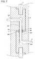
- Fig. 7 is a partial cross-sectional view showing another waterproof constitution of the hinge portion according to the first embodiment.
- ring grooves 105 and 505 having diameters wider than those of the non-through holes 103 and 503 are provided to entrances of the respective non-through holes 103 and 503 of the main body 1 and the function unit 5, and O-rings 9A and 9B are provided to the ring grooves 105 and 505.
- O-rings 9A and 9B are provided to the ring grooves 105 and 505.
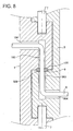
- Fig. 8 is a partial cross-sectional view showing still another waterproof constitution of the hinge portion according to the first embodiment.
- slopes 106 and 506 are provided to the entrances of the respective non-through holes 103 and 503 of the main body 1 and the function unit 5.
- the O-ring 9 is disposed with interference at three portions of the slopes 106 and 506 and the outer diameter of the communication cable 8. Thus, the inflow into the non-through holes 103 and 503 is prevented.
- the electric circuit of the main body 1 communicates with the electric circuit of the function unit 5 via the communication cable 8, and cooperates with the electric circuit of the function unit 5, thereby realizing an adding function corresponding to the function unit 5. For example, if the function unit 5 has an additional function of a PHS mobile, the main body 1 displays a telephone number and produces an incoming call sound. If the function unit 5 has an additional function of a GPS receiver, the main body 1 displays the present location, a moving speed, a moving distance, etc.
- the hinge axis 7 couples the function unit 5 to the main body 1 communicably and movably in the circumferential direction of the arm.
- the hinge axis 7 is bent with a proper angle, and therefore, the arm portable information apparatus 100 can be appropriately fit to the user's arm even if the operation portion or the display portion, the electric circuit or the like has a wide area.
- the main body 1 and the function unit 5 are not integrated and have no largely-bent shape, processing is easy and costs can be decreased. Also, since the main body 1 and the function unit 5 are provided separately, it is unnecessary to provide the main body every function and costs can be further decreased.
- Figs. 9A and 9B are a plan view and a side view showing the constitution of an arm portable information apparatus according to a second embodiment of the present invention.
- the fundamental constitution is the same as that of the first embodiment, and therefore, the same reference symbols denote the same portions as those in Fig. 5.
- the hinge portion 7 is provided at both ends of the main body 1 in the circumferential direction of the arm and two function units 5 are coupled to the main body 1.
- the two function units 5 are provided to be located at both the ends of the main body 1 in the circumferential direction of the arm.
- the two function units 5 are provided to be located at both the ends of the main body 1 in the circumferential direction of the arm. Therefore, in addition to the effects of the first embodiment, it is further advantage that the combination of a plurality of functions can be realized with reduced costs.
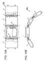
- Figs. 10A and 10B are a plan view and a side view showing the constitution of an arm portable information apparatus according to a third embodiment of the present invention.
- the hinge axis 7 is further provided to the function unit 5 and the new function unit 5 may be connected. That is, a plurality of the function units 5 may be coupled to link them together.
- Other constitution and operation are similar to those of the first embodiment and the second embodiment, and therefore, the description is omitted.
- At least two function units 5 are provided to be located at both ends of the main body 1 in the circumferential direction of the arm. Therefore, in addition to the effects of the first embodiment or second embodiment, it is further advantage that the combination of a plurality of functions can be realized with reduced costs.
- the coupling means couples the function unit communicably and movably to the main body in the circumferential direction of the arm.
- the apparatus can be appropriately fit to the thin arm and thick arm with reduced costs while the area of the electric circuit and the area of the operation portion, the display portion or the like is ensured.
- two function units are provided to be located at both ends of the main body in the circumferential direction of the arm.
- the coupling means is a hinge.
- the communication hole is formed to communicate with the end surface on the main body side and the end surface on the function unit side through the rotational axis of the hinge, and the communication cable communicates with the communication hole. Therefore, the main body can be coupled to the function unit communicably and movably while the communication cable is protected.
- the coupling means is a hinge
- the non-through hole is provided in the axial direction from the engagement surface of the rotational axis
- the through-hole which communicates from the non-through hole to the end surface on the main body side or to the end surface on the function unit side is provided, thereby forming the communication hole which communicates with the end surface on the main body side and the end surface on the function unit side.
- the main body can be coupled to the function unit communicably and movably while the communication cable is protected.
- the communication cable has the waterproof means at the boundary on the boundary surface between the main body and the function unit.
- the main body and the function unit mutually rotate.
- waterproofing in the communication cable can be assured, and the apparatus can be used even in a situation where the communication cable might otherwise get wet with water.
- At least two function units 5 are provided to the main body in the circumferential direction of the arm. Therefore, in addition to the effects of the first embodiment, it is further advantage that the combination of a plurality of functions can be realized with reduced costs.
Landscapes
- Engineering & Computer Science (AREA)
- Theoretical Computer Science (AREA)
- Computing Systems (AREA)
- Computer Hardware Design (AREA)
- Physics & Mathematics (AREA)
- General Engineering & Computer Science (AREA)
- General Physics & Mathematics (AREA)
- Telephone Set Structure (AREA)
- Casings For Electric Apparatus (AREA)
- Mobile Radio Communication Systems (AREA)
- Apparatus For Radiation Diagnosis (AREA)
Abstract
Description
Claims (9)
- An arm portable information apparatus comprising:wherein the arm portable information apparatus is fitted to an arm to be carried.a main body having an electric circuit for information processing;a function unit having an electric circuit for an adding function; andcoupling means for communicably and movably coupling the function unit with the main body in a circumferential direction of the arm;
- An arm portable information apparatus according to claim 1, wherein a number of the function units is two to be located at both ends of the main body in the circumferential direction of the arm upon fitting.
- An arm portable information apparatus according to claim 1, whereinthe coupling means is a hinge,a communication hole for communicating an end surface on the main body side and an end surface on the function unit side through a rotational axis of the hinge is formed, anda communication cable passes through the communication hole.
- An arm portable information apparatus according to claim 1, wherein the coupling means is a hinge, a non-through hole is provided in an axial direction from an engagement surface of a rotational axis of a joined hinge, a through-hole which communicates from the non-through hole to an end surface on the main body side or an end surface on the function unit side is provided, a communication hole which communicates with the end surface on the main body side and the end surface on the function unit side is formed , and a communication cable passes through the communication hole.
- An arm portable information apparatus according to claim 3, wherein waterproof means is provided to a divided part of the rotational axis of the hinge.
- An arm portable information apparatus according to claim 4, wherein waterproof means is provided to a divided part of the rotational axis of the hinge.
- An arm portable information apparatus according to claim 4, further comprising:ring-shaped waterproof means provided to an entrance of the non-through hole,interference provided to an outer diameter of the waterproof means and to an inner diameter of the non-through hole, andinterference provided to an inter diameter of the waterproof means and to an outer diameter of the communication cable to prevent inflow into the non-through hole.
- An arm portable information apparatus according to claim 4, further compring:ring-shaped waterproof means provided to an entrance of the non-through hole, andinterference provided in the rotational axis direction to prevent inflow into the non-through hole.
- An arm portable information apparatus according to claim 4, wherein at least two function units are coupled in the circumferential direction of the arm of the main body.
Applications Claiming Priority (2)
| Application Number | Priority Date | Filing Date | Title |
|---|---|---|---|
| JP2000231974A JP2002050997A (en) | 2000-07-31 | 2000-07-31 | Arm portable information device |
| JP2000231974 | 2000-07-31 |
Publications (2)
| Publication Number | Publication Date |
|---|---|
| EP1177736A2 true EP1177736A2 (en) | 2002-02-06 |
| EP1177736A3 EP1177736A3 (en) | 2003-05-07 |
Family
ID=18724722
Family Applications (1)
| Application Number | Title | Priority Date | Filing Date |
|---|---|---|---|
| EP01306154A Withdrawn EP1177736A3 (en) | 2000-07-31 | 2001-07-17 | Arm portable information apparatus |
Country Status (5)
| Country | Link |
|---|---|
| US (1) | US20020012292A1 (en) |
| EP (1) | EP1177736A3 (en) |
| JP (1) | JP2002050997A (en) |
| KR (1) | KR20020010878A (en) |
| TW (1) | TW480376B (en) |
Cited By (2)
| Publication number | Priority date | Publication date | Assignee | Title |
|---|---|---|---|---|
| EP2965155A2 (en) * | 2013-03-08 | 2016-01-13 | TomTom International B.V. | Fitness watch case |
| EP3023845A1 (en) * | 2014-11-18 | 2016-05-25 | Sony Corporation | Band type electronic device and substrate arrangement method |
Families Citing this family (17)
| Publication number | Priority date | Publication date | Assignee | Title |
|---|---|---|---|---|
| US7251512B2 (en) | 2002-05-13 | 2007-07-31 | Nec Corporation | Water-proof collapsible cellular terminal apparatus |
| US9016565B2 (en) * | 2011-07-18 | 2015-04-28 | Dylan T X Zhou | Wearable personal digital device for facilitating mobile device payments and personal use |
| US7408846B2 (en) * | 2005-03-11 | 2008-08-05 | Fredi Brodmann | Ornamental article |
| USD620820S1 (en) * | 2008-06-09 | 2010-08-03 | The F3M3 Companies, Inc. | Remote control for personal tracking |
| US8851372B2 (en) * | 2011-07-18 | 2014-10-07 | Tiger T G Zhou | Wearable personal digital device with changeable bendable battery and expandable display used as standalone electronic payment card |
| US8467270B2 (en) * | 2011-10-26 | 2013-06-18 | Google Inc. | Smart-watch with user interface features |
| JP2015079328A (en) * | 2013-10-16 | 2015-04-23 | ソニー株式会社 | INPUT DEVICE AND ELECTRONIC DEVICE HAVING THE SAME |
| US20150146355A1 (en) * | 2013-11-13 | 2015-05-28 | Aliphcom | Alignment of components coupled to a flexible substrate for wearable devices |
| WO2015073737A1 (en) * | 2013-11-13 | 2015-05-21 | Aliphcom | Conductive structures for a flexible substrate in a wearable device |
| US9668367B2 (en) * | 2014-02-04 | 2017-05-30 | Microsoft Technology Licensing, Llc | Wearable computing systems |
| CN103916497A (en) * | 2014-03-25 | 2014-07-09 | 京东方科技集团股份有限公司 | Auxiliary equipment of mobile terminal and mobile terminal product |
| GB201405673D0 (en) * | 2014-03-28 | 2014-05-14 | Tomtom Int Bv | Heart rate monitor and strap |
| CN104238349B (en) * | 2014-07-25 | 2017-01-18 | 京东方科技集团股份有限公司 | Intelligent watch |
| US9471102B2 (en) * | 2014-08-28 | 2016-10-18 | Pebble Technology, Corp. | Connection by securing device with integrated circuitry layer |
| USD859412S1 (en) * | 2017-08-18 | 2019-09-10 | Practech, Inc. | Wearable or handheld hybrid smart barcode scanner |
| CN111466890B (en) * | 2020-04-17 | 2023-03-07 | 北京石油化工学院 | Wearable respiratory and body temperature monitoring device |
| US12093088B2 (en) * | 2022-06-06 | 2024-09-17 | Apple Inc. | Modular light assembly for a wearable device |
Family Cites Families (5)
| Publication number | Priority date | Publication date | Assignee | Title |
|---|---|---|---|---|
| US3977176A (en) * | 1974-08-22 | 1976-08-31 | Citizen Watch Co., Ltd. | Electronic watch structure |
| CH647916GA3 (en) * | 1981-08-25 | 1985-02-28 | ||
| FR2664438B1 (en) * | 1990-07-04 | 1994-07-22 | Alcatel Radiotelephone | DEVICE FORMED FROM TWO ARTICULATED ELEMENTS AROUND A HINGE AND CONNECTED BY AN ELECTRICAL CONNECTION. |
| EP0660204B1 (en) * | 1993-07-05 | 2000-04-12 | Seiko Epson Corporation | Electronic device having wearing band |
| FR2793898B1 (en) * | 1999-05-17 | 2001-08-10 | Timentel Pty Ltd | ARTICULATED ELECTRONIC WATCH |
-
2000
- 2000-07-31 JP JP2000231974A patent/JP2002050997A/en active Pending
-
2001
- 2001-07-05 TW TW090116459A patent/TW480376B/en not_active IP Right Cessation
- 2001-07-17 EP EP01306154A patent/EP1177736A3/en not_active Withdrawn
- 2001-07-26 US US09/915,594 patent/US20020012292A1/en not_active Abandoned
- 2001-07-31 KR KR1020010046200A patent/KR20020010878A/en not_active Withdrawn
Cited By (4)
| Publication number | Priority date | Publication date | Assignee | Title |
|---|---|---|---|---|
| EP2965155A2 (en) * | 2013-03-08 | 2016-01-13 | TomTom International B.V. | Fitness watch case |
| EP3023845A1 (en) * | 2014-11-18 | 2016-05-25 | Sony Corporation | Band type electronic device and substrate arrangement method |
| US9720376B2 (en) | 2014-11-18 | 2017-08-01 | Sony Corporation | Band type electronic device and substrate arrangement method |
| US10620587B2 (en) | 2014-11-18 | 2020-04-14 | Sony Corporation | Band type electronic device and substrate arrangement method |
Also Published As
| Publication number | Publication date |
|---|---|
| US20020012292A1 (en) | 2002-01-31 |
| JP2002050997A (en) | 2002-02-15 |
| KR20020010878A (en) | 2002-02-06 |
| TW480376B (en) | 2002-03-21 |
| EP1177736A3 (en) | 2003-05-07 |
Similar Documents
| Publication | Publication Date | Title |
|---|---|---|
| US20020012292A1 (en) | Arm portable information apparatus | |
| CN100514747C (en) | Portable radio device | |
| CN101098158B (en) | Mobile radio communication device | |
| EP3588920B1 (en) | Camera decoration for a camera module in an electronic apparatus | |
| KR20030021564A (en) | Rotational lens housing mounting device and folder-type telephone therewith | |
| US7047053B2 (en) | Mobile terminal | |
| GB2366082A (en) | Portable radio device with metal cover | |
| JPH06311216A (en) | Mobile phone | |
| JP2001189786A (en) | Portable wireless communication devices such as mobile phones | |
| US20040222930A1 (en) | Wrist antenna | |
| US7856256B2 (en) | Foldable portable terminal device | |
| US6725070B2 (en) | Portable radio device | |
| JP2976936B2 (en) | Portable wireless information terminal | |
| KR20050011773A (en) | Cradle with beam projector for phone | |
| CN110413047B (en) | Electronic device | |
| JP2923257B2 (en) | Mobile phone protective cover | |
| JP3923984B2 (en) | Wireless communication terminal | |
| JPH11331017A (en) | Portable mobile communication terminal | |
| JP2001189788A (en) | Portable wireless communication devices such as mobile phones | |
| KR20130001731U (en) | Wireless headset of wristwatch shape | |
| KR100810250B1 (en) | Handheld terminal with self-clip | |
| KR100594064B1 (en) | Portable phone with stereo sound | |
| KR200222278Y1 (en) | A Mobile Telephone Terminal Using Antenna | |
| JP4080903B2 (en) | Electroacoustic transducer structure and portable terminal device using the same | |
| KR200257681Y1 (en) | System for Antitheft And Antilostness of Moveable electroniture |
Legal Events
| Date | Code | Title | Description |
|---|---|---|---|
| PUAI | Public reference made under article 153(3) epc to a published international application that has entered the european phase |
Free format text: ORIGINAL CODE: 0009012 |
|
| AK | Designated contracting states |
Kind code of ref document: A2 Designated state(s): AT BE CH CY DE DK ES FI FR GB GR IE IT LI LU MC NL PT SE TR |
|
| AX | Request for extension of the european patent |
Free format text: AL;LT;LV;MK;RO;SI |
|
| PUAL | Search report despatched |
Free format text: ORIGINAL CODE: 0009013 |
|
| AK | Designated contracting states |
Designated state(s): AT BE CH CY DE DK ES FI FR GB GR IE IT LI LU MC NL PT SE TR |
|
| AX | Request for extension of the european patent |
Extension state: AL LT LV MK RO SI |
|
| RIC1 | Information provided on ipc code assigned before grant |
Ipc: 7G 04G 1/00 B Ipc: 7H 01R 35/02 B Ipc: 7A 44C 5/00 B Ipc: 7A 44C 5/10 A |
|
| AKX | Designation fees paid | ||
| REG | Reference to a national code |
Ref country code: DE Ref legal event code: 8566 |
|
| STAA | Information on the status of an ep patent application or granted ep patent |
Free format text: STATUS: THE APPLICATION IS DEEMED TO BE WITHDRAWN |
|
| 18D | Application deemed to be withdrawn |
Effective date: 20031108 |