EP1177639B1 - Quantization in perceptual audio coders with compensation for synthesis filter noise spreading - Google Patents
Quantization in perceptual audio coders with compensation for synthesis filter noise spreading Download PDFInfo
- Publication number
- EP1177639B1 EP1177639B1 EP00923218A EP00923218A EP1177639B1 EP 1177639 B1 EP1177639 B1 EP 1177639B1 EP 00923218 A EP00923218 A EP 00923218A EP 00923218 A EP00923218 A EP 00923218A EP 1177639 B1 EP1177639 B1 EP 1177639B1
- Authority
- EP
- European Patent Office
- Prior art keywords
- noise
- synthesis
- quantization
- filter
- subband
- Prior art date
- Legal status (The legal status is an assumption and is not a legal conclusion. Google has not performed a legal analysis and makes no representation as to the accuracy of the status listed.)
- Expired - Lifetime
Links
- 238000013139 quantization Methods 0.000 title claims description 129
- 230000015572 biosynthetic process Effects 0.000 title claims description 97
- 238000003786 synthesis reaction Methods 0.000 title claims description 97
- 238000003892 spreading Methods 0.000 title claims description 79
- 230000007480 spreading Effects 0.000 title description 30
- 238000000034 method Methods 0.000 claims description 105
- 230000008569 process Effects 0.000 claims description 73
- 238000001228 spectrum Methods 0.000 claims description 54
- 238000004458 analytical method Methods 0.000 claims description 42
- 230000004044 response Effects 0.000 claims description 24
- 238000012545 processing Methods 0.000 claims description 17
- 238000004590 computer program Methods 0.000 claims 2
- 230000003595 spectral effect Effects 0.000 description 35
- 230000006870 function Effects 0.000 description 31
- 230000005236 sound signal Effects 0.000 description 26
- 230000014509 gene expression Effects 0.000 description 23
- 230000000873 masking effect Effects 0.000 description 21
- 239000011159 matrix material Substances 0.000 description 15
- 238000005457 optimization Methods 0.000 description 12
- 230000002829 reductive effect Effects 0.000 description 11
- 238000003860 storage Methods 0.000 description 8
- 239000000284 extract Substances 0.000 description 6
- 230000000295 complement effect Effects 0.000 description 5
- 238000010586 diagram Methods 0.000 description 5
- 230000000694 effects Effects 0.000 description 5
- 230000003287 optical effect Effects 0.000 description 5
- 238000012937 correction Methods 0.000 description 4
- 230000005540 biological transmission Effects 0.000 description 3
- 238000004364 calculation method Methods 0.000 description 3
- 238000006243 chemical reaction Methods 0.000 description 3
- 238000004891 communication Methods 0.000 description 3
- 238000012986 modification Methods 0.000 description 3
- 230000004048 modification Effects 0.000 description 3
- 230000003466 anti-cipated effect Effects 0.000 description 2
- 238000013459 approach Methods 0.000 description 2
- 230000007812 deficiency Effects 0.000 description 2
- 238000005516 engineering process Methods 0.000 description 2
- 230000002441 reversible effect Effects 0.000 description 2
- 101100445834 Drosophila melanogaster E(z) gene Proteins 0.000 description 1
- 230000003247 decreasing effect Effects 0.000 description 1
- 238000009432 framing Methods 0.000 description 1
- 230000001788 irregular Effects 0.000 description 1
- 230000000670 limiting effect Effects 0.000 description 1
- 238000004519 manufacturing process Methods 0.000 description 1
- 230000002085 persistent effect Effects 0.000 description 1
- 230000009467 reduction Effects 0.000 description 1
- 238000006467 substitution reaction Methods 0.000 description 1
- 230000007704 transition Effects 0.000 description 1
Images


Classifications
-
- G—PHYSICS
- G10—MUSICAL INSTRUMENTS; ACOUSTICS
- G10L—SPEECH ANALYSIS TECHNIQUES OR SPEECH SYNTHESIS; SPEECH RECOGNITION; SPEECH OR VOICE PROCESSING TECHNIQUES; SPEECH OR AUDIO CODING OR DECODING
- G10L19/00—Speech or audio signals analysis-synthesis techniques for redundancy reduction, e.g. in vocoders; Coding or decoding of speech or audio signals, using source filter models or psychoacoustic analysis
- G10L19/02—Speech or audio signals analysis-synthesis techniques for redundancy reduction, e.g. in vocoders; Coding or decoding of speech or audio signals, using source filter models or psychoacoustic analysis using spectral analysis, e.g. transform vocoders or subband vocoders
- G10L19/032—Quantisation or dequantisation of spectral components
-
- G—PHYSICS
- G10—MUSICAL INSTRUMENTS; ACOUSTICS
- G10L—SPEECH ANALYSIS TECHNIQUES OR SPEECH SYNTHESIS; SPEECH RECOGNITION; SPEECH OR VOICE PROCESSING TECHNIQUES; SPEECH OR AUDIO CODING OR DECODING
- G10L19/00—Speech or audio signals analysis-synthesis techniques for redundancy reduction, e.g. in vocoders; Coding or decoding of speech or audio signals, using source filter models or psychoacoustic analysis
- G10L19/002—Dynamic bit allocation
-
- G—PHYSICS
- G10—MUSICAL INSTRUMENTS; ACOUSTICS
- G10L—SPEECH ANALYSIS TECHNIQUES OR SPEECH SYNTHESIS; SPEECH RECOGNITION; SPEECH OR VOICE PROCESSING TECHNIQUES; SPEECH OR AUDIO CODING OR DECODING
- G10L19/00—Speech or audio signals analysis-synthesis techniques for redundancy reduction, e.g. in vocoders; Coding or decoding of speech or audio signals, using source filter models or psychoacoustic analysis
- G10L19/02—Speech or audio signals analysis-synthesis techniques for redundancy reduction, e.g. in vocoders; Coding or decoding of speech or audio signals, using source filter models or psychoacoustic analysis using spectral analysis, e.g. transform vocoders or subband vocoders
- G10L19/0204—Speech or audio signals analysis-synthesis techniques for redundancy reduction, e.g. in vocoders; Coding or decoding of speech or audio signals, using source filter models or psychoacoustic analysis using spectral analysis, e.g. transform vocoders or subband vocoders using subband decomposition
Definitions
- the present invention relates generally to the perceptual coding of digital audio signals that uses analysis filters for encoding and synthesis filters for decoding.
- the present invention relates more particularly to the quantization of subband signals in perceptual coders that takes into account the spreading of quantization noise by the synthesis filters.
- Perceptual coding systems attempt to achieve these conflicting goals by using a process that encodes and quantizes the audio signals in a manner that uses larger spectral components within the audio signal to mask or render inaudible the resultant quantizing noise.
- a perceptual encoding process may be performed by a so called split-band encoder that applies a bank of analysis filters to the audio signal to obtain subband signals having bandwidths that are commensurate with the critical bands of the human auditory system, estimates the masking threshold of the audio signal by applying a perceptual model to the subband signals or to some other measure of audio signal spectral content, establishes a quantization resolution for quantizing each subband signal that is just small enough so that the resultant quantizing noise lies just below the estimated masking threshold of the audio signal, and generates an encoded signal by assembling the quantized subband signals into a form suitable for transmission or storage.
- a complementary perceptual decoding process may be performed by a split-band decoder that extracts the quantized subband signals from the encoded signal, obtains dequantized representations of the quantized subband signals, and applies a bank of synthesis filters to the dequantized representations to generate an audio signal that is, ideally, perceptually indistinguishable from the original audio signal.
- the perceptual models that are often used to determine the quantization resolution generally assume that the quantization noise introduced into the quantized subband signals is substantially the same as the noise that results in the output signal obtained by applying a bank of synthesis filters to the quantized subband signals. In general, this assumption is not true because the synthesis filters modify or spread the quantization noise spectrum. As a consequence, quantization performed strictly according to the quantization resolutions obtained by applying these perceptual models usually results in audible noise in the output signal obtained from the synthesis filters.
- the subband signals each comprise a group of one or more frequency-domain transform coefficients.
- the synthesis filter noise-spreading property mentioned above is related to the fact that the complementary analysis and synthesis filters used in these coding systems do not implement ideal filters having a flat unitary-gain in the passband, zero-gain in the stopbands, and infinitely steep transitions between the stopbands and the passband.
- the analysis filters provide only a distorted measure of the spectral content of an input audio signal.
- some filters such as the quadrature mirror filter (QMF) and the time-domain aliasing cancellation (TDAC) transforms generate significant aliasing artifacts that further distort the spectral measure of the input signal.
- QMF quadrature mirror filter
- TDAC time-domain aliasing cancellation
- This deficiency can be compensated to some degree by either forcing the level of the estimated masking threshold to be lower than an accurate perceptual model would indicate, or by uniformly decreasing the quantization resolution below that which an accurate perceptual model would indicate is sufficient to render the quantizing noise inaudible. Neither form of compensation is optimum because they do not properly account for the cause of the deficiency.
- U.S. patent 5,623,577 discloses several techniques that compensate for the noise-spreading effect of synthesis filters.
- the theoretical basis of the disclosed techniques assumes the degree of noise spreading can be determined by convolving the quantization noise spectrum with the synthesis filter frequency response.
- Disclosed embodiments of the techniques determine whether compensation for synthesis filter noise spreading is required by comparing frequency-domain slopes of an estimated masking threshold with threshold values that are determined empirically.
- these techniques are not optimum because the accuracy for determining whether compensation is needed is suboptimal, the steps required to obtain the needed empirical threshold values are expensive and time consuming, and the disclosed techniques do not take into consideration the effects of overlap-add processes that are included in some synthesis filters such as QMF and the TDAC transforms.
- the disclosed techniques do not provide an ability for a particular embodiment to gracefully tradeoff the accuracy of compensation against the computational resources required to carry out the embodiment.
- EP-A-0 722 225 discloses an audio coding method that converts a time-domain signal into a short-term spectrum, which is encoded and transmitted for subsequent decoding. At the time of decoding, the short-term spectrum is converted back into the time domain. The conversion back into the time domain can create audible noise even though the noise created by the coding process does not exceed a masking spectrum based on a psychoacoustic model. This noise is avoided by modifying the psychoacoustic model and, consequently, the coding method to account for the effects of the conversion from the short-term spectrum back into the time domain. Because the noise spreading effects of the conversion back into the time domain are considered with respect to one signal block as modified by an analysis window function, the coding provided by this method is also suboptimum.
- Advantageous embodiments of the present invention are able to determine the need for noise-spreading compensation in a manner that is more accurate than other known methods and to provide a graceful tradeoff between the accuracy of compensation and the level of computational resources required to provide the compensation.
- a method or apparatus determines quantization resolutions for subband signals obtained from analysis filters applied to an input signal by generating a desired noise spectrum in response to the input signal and applying a synthesis-filter noise-spreading model to obtain estimated noise levels in subbands of an output signal obtained from synthesis filters.
- the synthesis-filter noise-spreading model represents noise-spreading characteristics of the synthesis filters and an overlap-add process, and the quantization resolutions are determined such that the desired-noise spectrum is greater than the estimated noise levels.
- the method may be embodied as a program of instructions on a medium that is readable by a device for execution by the device.
- a medium conveys encoded information that comprises signal information that represents quantized components of subband signals generated by applying analysis filters to an input signal and control information that represents quantizing resolutions of the quantized subband signal components.
- the quantizing resolutions are determined as summarized above.
- an apparatus receives and decodes a signal conveying the encoded information summarized above.
- the receiver comprises an input coupled to the signal conveying the encoded information; one or more processing circuits coupled to the input that extract the signal information and the control information from the encoded information and obtain therefrom the quantized subband signal components and the quantizing resolutions of the quantized subband signal components, dequantize the quantized subband signal components according to the quantizing resolutions to obtain dequantized subband signals, and apply synthesis filters to the dequantized subband signals and apply an overlap-add process to blocks of information obtained from the synthesis filters to generate an output signal.
- the quantizing noise in the subband signals is spread by the synthesis filters and the overlap-add process to produce noise levels in subbands of the output signal that are less than the desired-noise spectrum; and an output coupled to the one or more processing circuits that conveys the output signal.
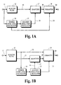
- Fig. 1A illustrates one embodiment of a split-band encoder incorporating various aspects of the present invention in which a bank of analysis filters 12 is applied to a digital audio signal received from path 11 to generate frequency-subband signals along path 13.
- the bank of analysis filters may be implemented in a wide variety of ways.
- the bank of filters is implemented by weighting or modulating overlapped blocks of digital audio samples with an analysis window function and applying a particular Modified Discrete Cosine Transform (MDCT) to the window-weighted blocks.
- MDCT Modified Discrete Cosine Transform
- This MDCT is referred to as a Time-Domain Aliasing Cancellation (TDAC) transform and is disclosed in Princen, Johnson and Bradley, "Subband/Transform Coding Using Filter Bank Designs Based on Time Domain Aliasing Cancellation," Proc. Int. Conf. Acoust., Speech, and Signal Proc. , May 1987, pp. 2161-2164.
- TDAC Time-Domain Aliasing Cancellation
- desired noise level calculator 14 analyzes the digital audio signal received from path 11 to estimate the psychoacoustic masking threshold of the audio signal and to obtain a desired noise level in response thereto
- the desired noise level is established at a level that is substantially equal to the psychoacoustic masking threshold that is obtained using a good perceptual model such as those disclosed in Schroeder, Atal and Hall, "Optimizing Digital Speech Coders by Exploiting Masking Properties of the Human Ear," J. Acoust. Soc. Am. , December 1979, pp. 1647-1652 and in U.S. patent 5,623,577.
- a good perceptual model such as those disclosed in Schroeder, Atal and Hall, "Optimizing Digital Speech Coders by Exploiting Masking Properties of the Human Ear," J. Acoust. Soc. Am. , December 1979, pp. 1647-1652 and in U.S. patent 5,623,577.
- quantize resolution calculator 15 uses a noise-spreading model to determine the quantization resolutions to use for quantizing the subband signals and passes an indication of these quantization resolutions along path 16.
- the noise-spreading model represents the noise-spreading characteristics of a bank of synthesis filters and is used to estimate the noise in an output signal that is obtained by applying the synthesis filters to the subband signals that are quantized according to the quantization resolutions.
- Quantize resolution calculator 15 determines the quantization resolutions such that, according to the noise-spreading model, the output signal obtained from the synthesis filters has a level of noise resulting from the quantization that is substantially equal to the desired noise level.
- Quantizer 17 quantizes the subband signals received from path 13 according to the quantization resolution information received from path 16 to generate quantized signals along path 18.
- Quantizer 17 may be implemented by a variety of quantization functions using uniform or non-uniform step sizes including linear quantization, logarithmic quantization, Lloyd-Max quantization and vector quantization.
- the resolution of the quantization provided by quantizer 17 may be controlled by varying the number of quantization steps, varying the dynamic range represented by a given number of steps, and/or altering the values represented by each quantization step. In some embodiments, the number of quantization steps is varied by allocating a number of bits and selecting a quantizer with a corresponding number of steps.
- Formatter 19 assembles the quantized signals into an encoded signal and passes the encoded signal along path 20 to be conveyed by transmission media such as baseband or modulated communication paths throughout the spectrum including from supersonic to ultraviolet frequencies) or storage media including those that convey information using essentially any magnetic or optical recording technology including magnetic tape, magnetic disk, and optical disc.
- transmission media such as baseband or modulated communication paths throughout the spectrum including from supersonic to ultraviolet frequencies
- storage media including those that convey information using essentially any magnetic or optical recording technology including magnetic tape, magnetic disk, and optical disc.
- an indication of the signal characteristics used by desired noise level calculator 14 is passed along path 21 and assembled into the encoded signal.
- neither path 21 nor the information passed along path 21 are needed because an indication of the quantization resolutions used to generate the quantized signals is assembled into the encoded signal.
- Formatter 19 may also use an entropy encoder or other form of lossless encoder to reduce the information capacity requirements of the encoded signal.
- Fig. 1B illustrates another embodiment of a split-band encoder incorporating various aspects of the present invention that is similar to the embodiment discussed above. A few of the differences between these two embodiments are discussed here.
- a bank of analysis filters 12 is applied to a digital audio signal received from path 11 to generate frequency-subband signals along path 13 and to generate information representing the input signal spectral envelope along path 22.
- subband signal components may be represented in a block-floating-point (BFP) form in which the BFP exponents are essentially logarithmic scaling factors representing the peak component value in each subband.
- BFP exponents may be used as the input signal spectral envelope information.
- the bank of analysis filters may be implemented in a wide variety of ways as discussed above.
- Desired noise level calculator 14 analyzes the spectral envelope information received from path 22 to estimate the psychoacoustic masking threshold of the audio signal and to obtain a desired noise level in response thereto.
- quantize resolution calculator 15 uses a noise-spreading model as explained above to determine the quantization resolutions to use for quantizing the subband signals and passes an indication of these quantization resolutions along path 16.
- Quantizer 17 quantizes the subband signals received from path 13 according to the quantization resolution information received from path 16 to generate quantized signals along path 18. Quantizer 17 may be implemented and controlled as discussed above. Formatter 19 assembles the quantized signals received from path 18 and the spectral envelope information received from path 22 into an encoded signal and passes the encoded signal along path 20 as explained above. Formatter 19 may also use an entropy encoder or other form of lossless encoder as discussed above.
- Fig. 1B may be used in backward-adaptive coding systems because the information needed by the desired-noise-level calculator is conveyed in the encoded signal by the spectral envelope information. No additional information is needed by a complementary decoder that incorporates counterpart components to desired noise level calculator 14 and quantize resolution calculator 15.
- desired noise level calculator 14 provides a set of initial quantization resolutions and quantize resolution calculator 15 modifies one or more of these initial resolutions as necessary to carry out noise-spreading compensation according to the synthesis-filter noise-spreading model discussed above. An indication of these modifications is passed along path 23 and assembled into the encoded signal by formatter 19. By including this additional information, the encoded signal can be decoded without use of the synthesis-filter noise-spreading model.
- Fig. 2A illustrates one embodiment of a split-band decoder incorporating various aspects of the present invention in which deformatter 32 extracts quantized signals from an encoded signal received from path 31 and passes the quantized signals along path 33.
- Deformatter 32 may also use an entropy decoder or other form of lossless decoder as necessary to obtain the quantized signals.
- deformatter 32 also extracts from the encoded signal an indication of the signal characteristics used by desired noise level calculator in a companion encoder and passes this indication to desired noise level calculator 34, which obtains the desired noise level in response thereto.
- quantize resolution calculator 35 uses a noise-spreading model as explained above to determine the quantization resolutions that were used to generate the quantized signals and passes an indication of these resolutions along path 36
- Dequantizer 37 dequantizes the quantized signals received from path 33 according to the quantization resolution information received from path 36 and generates dequantized subband signals along path 38.
- Dequantizer 37 may be implemented and controlled in a variety of ways as discussed above for quantization. No particular dequantization function is critical in principle to the practice of the present invention but should be complementary to the quantization process used to generate the quantized subband signals.
- a bank of synthesis filters 39 is applied to these dequantized subband signals to generate an output signal along path 40.
- the bank of synthesis filters may be implemented in a wide variety of ways.
- the bank of synthesis filters is implemented by applying an inverse MDCT, referred to as the inverse TDAC transform, to blocks of transform coefficients, weighting the signal samples obtained from the transform with a synthesis window function, and overlapping and adding samples in adjacent window-weighted blocks.
- neither desired noise level calculator 34 nor quantize resolution calculator 35 are needed because deformatter 32 is able to extract quantization resolution information from the encoded signal and provide this information to quantizer 37.
- Fig. 2B illustrates another embodiment of a split-band decoder incorporating various aspects of the present invention that is similar to the embodiment discussed above. A few of the differences between these two embodiments are discussed here.
- Deformatter 32 extracts quantized signals from an encoded signal received from path 31 and passes the quantized signals along path 33, and extracts information representing the encoded signal spectral envelope and pass this information along path 42. Deformatter 32 may also use an entropy decoder or other form of lossless decoder as necessary to reverse any lossless coding used to generate the encoded signal.
- Desired noise level calculator 34 analyzes the spectral envelope information received from path 42, which obtains the desired noise level in response thereto.
- quantize resolution calculator 35 uses a noise-spreading model as explained above to determine the quantization resolutions that were used to generate the quantized signals and passes an indication of these resolutions along path 36
- Dequantizer 37 dequantizes the quantized signals received from path 33 according to the quantization resolution information received from path 36 and generates dequantized subband signals along path 38. Dequantizer 37 may be implemented and controlled as discussed above. A bank of synthesis filters 39 is applied to the dequantized subband signals and the spectral envelope information to generate an output signal along path 40.
- desired noise level calculator 34 provides a set of initial quantization resolutions and one or more modifications to these initial resolutions are obtained from the encoded signal by deformatter 32. These modifications may be applied to the initial quantization resolutions to provide noise-spreading compensation.
- the quantization process in many perceptual coding systems determines the quantization resolution to use for quantizing a subband signal from the difference between the amplitude of the subband signal and the level of an estimated psychoacoustic masking threshold within that subband.
- An implicit assumption in this process is that the quantization noise for one transform coefficient is independent of the quantization noise for other neighboring transform coefficients. Generally, this assumption is not true because of the noise-spreading characteristics of the synthesis filters.
- the degree of noise spreading is affected by the spectral selectivity of the synthesis filters.
- the analysis and synthesis filters used in coding systems do not provide ideal passbands.
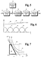
- a schematic illustration of the frequency response for a hypothetical synthesis filter is shown in Fig. 3.
- the response shown in the figure is a frequency-domain representation of a hypothetical output signal obtained from the synthesis filter in response to an input signal having a single spectral component at frequency f 0 .
- the main lobe 23 of the frequency response that is centered at frequency f 0 is the filter passband.
- the smaller side lobes of the response are in the filter stopbands.
- This spectral selectivity may be controlled by varying a number of factors including the length of the inverse transform and the shape of the synthesis window function.
- the width of the passband can often be traded off against the level of attenuation provided in the stopbands.
- the spectral selectivity can also be increased by increasing the length of the transform; however, the use of longer transforms is not always possible.
- a short length transform must be used to satisfy coding delay limitations.
- the noise-spreading characteristics of synthesis filters is particularly serious in such coding systems. Additional considerations for low-delay coding systems is discussed in U.S. patent 5,222,189.
- noise-spreading is usually more serious for medium to low frequencies because the critical bands of the human auditory system are narrower at lower frequencies.
- Each critical band corresponds to the masking threshold for a spectral component within that band and represents the range of frequencies over which a dominant spectral component can likely mask other smaller spectral components like quantization noise.
- the masking threshold can become narrower than the frequency selectivity of the synthesis filter. This means it is more likely the synthesis filter will spread noise resulting from the quantization of a spectral component outside the masking threshold of that spectral component.
- Fig. 4A provides a schematic illustration of a perceptual masking threshold 25 for a high-frequency spectral component at frequency f 0 as compared to the filter frequency response illustrated in Fig. 3.
- masking threshold 25 for the high-frequency spectral component at frequency f 0 is wide enough to completely cover the synthesis filter response. This suggests that a relatively large amount of noise resulting from the quantization of the high-frequency spectral component at frequency f 0 that is spread by the synthesis filter is likely to be masked by the spectral component.
- Fig. 4B provides a schematic illustration of a perceptual masking threshold 27 for a medium- to low-frequency spectral component at frequency f 0 as compared to the filter frequency response illustrated in Fig. 3.
- the low-frequency side of masking threshold 27 for the lower-frequency spectral component at frequency f 0 does not cover the synthesis filter response. This suggests that only a relatively small amount of noise resulting from the quantization of the lower-frequency spectral component at frequency f 0 that is spread by the synthesis filter is likely to be masked by the spectral component.
- a quantization process according to the present invention takes into account the noise-spreading characteristics of the synthesis filters to establish quantization resolutions just fine enough to render the quantization noise inaudible.
- analysis filter 52 represents a bank of analysis filters in a split-band encoder that generates transform coefficients constituting a frequency-domain representation of the audio signal received from path 51.
- Quantizing noise 53 represents a process that injects quantization noise into the frequency-domain representation obtained from analysis filter 52.
- Synthesis transform 54 and overlap-add 55 collectively represent a bank of synthesis filters in a split-band decoder.
- Synthesis transform 54 obtains a time-domain representation from the quantized frequency-domain representation of the audio signal.
- the process performed by overlap-add 55 overlaps adjacent blocks of samples in the time-domain representation obtained from synthesis transform 54 and adds corresponding samples in the overlapped blocks.
- Analysis filter 56 is a theoretical construct that is used to explain some principles of the present invention.
- the bank of analysis filters 52 is implemented by suitable analysis window functions and the TDAC MDCT and is applied to a sequence of blocks of audio signal samples that are received from path 51 to generate subband signals in the form of a sequence of blocks of transform coefficients. This may be expressed as: where
- Overlap-add 55 recovers a replica of the audio signal samples received from path 51 by applying a synthesis window function to each block of time-domain samples that is obtained from synthesis transform 54, overlapping the windowed blocks and adding corresponding time-domain samples in the overlapped blocks.
- the gain profile of a sequence of overlapping windowed blocks is shown in Fig. 6.
- Curve 41 illustrates the gain profile of a synthesis window function that is used to modulate a block of time-domain samples that is coextensive with line 44.
- curves 42 and 43 illustrate the gain profiles of synthesis window functions that are used to modulate blocks of time-domain samples that are coextensive with lines 45 and 46, respectively
- Signal samples representing a replica of the original audio signal samples within the interval illustrated by line 45 are obtained from the overlap-add process by adding the corresponding time-domain samples in the overlapping windowed blocks 41, 42 and 43.
- the bank of analysis filters 56 may be implemented by essentially any type of analysis filter. For purposes of illustration, this bank of analysis filters is implemented by a rectangular analysis window function and the TDAC MDCT discussed above for analysis filters 52.
- the bank of analysis filters 56 is applied to the replica signal samples to obtain a hypothetical frequency-domain representation of the replica signal, which is passed along path 57.
- the frequency-domain representation is used as a basis for an analytical expression of the noise-spreading characteristics of the synthesis filters.
- the hypothetical frequency-domain representation obtained from analysis filter 56 for this perfect reconstruction may be expressed as
- a process for quantization that takes proper account of synthesis filter noise spreading may be developed from an analytical expression of the relationship between the noise spectrum of the output signal obtained from the synthesis filter and the noise spectrum of the quantized input signal provided to the synthesis filter.
- a denvation of this analytical expression or "spreading matrix" will now be described
- the W matrix is the spreading matrix referred to above
- curve 71 is a smoothed measure of spectral power for a block m of transform coefficients X m ( k ) representing an audio signal
- curve 72 is the desired noise spectrum N ( k )
- curve 73 is a quantizing-noise spectrum N I,m ( k ) for the transform coefficients in block m that is obtained by multiplying the desired noise spectrum by gain factors g ( k ). As shown in the figure, it is anticipated that the gain factors are normally in the range from zero to one.
- equation 18 By substituting equation 18 into expression 16, it can be seen that N (0) ⁇ W (0,0) ⁇ g (0) ⁇ N (0) + W (0,1) ⁇ g (1) ⁇ N (1) and N (1) ⁇ W (1,0) ⁇ g (0) ⁇ N (0)+ W (1,1) ⁇ g (1) ⁇ N (1), where 0 ⁇ g (0) ⁇ 1 and 0 ⁇ g (1) ⁇ 1.
- the search for gain factor values that provide an optimal solution can be framed as a linearly constrained optimization problem that seeks to minimize the cost of the compensation.
- the cost is equal to one bit per transform coefficient for each -6.02 dB the quantizing noise spectrum is changed. For example, if gain factor g (1) is set equal to 0.25, then N I,m (1) of the quantizing noise spectrum is changed by -12.04 dB with respect to N (1) of the desired noise spectrum.
- the cost of compensation varies inversely with the logarithm of each gain factor.
- the total cost of compensation in this two-dimensional example is proportional to -log g (0) - log g (1).
- the constant of proportionality is assumed herein to be equal to one.
- the goal of the optimization problem is to minimize the cost of compensation under the constraints imposed by expressions 19a, 19b and 19c.
- the first step in framing quantization as a linear optimization problem is to replace each N ( j ) ⁇ W ( i , j ) term in expressions 19a and 19b with an element D ( i , j ) of a matrix D. All elements in matrix D are known to be positive because each element represents the product of two positive quantities.
- the results of this replacement may be expressed as N (0) ⁇ D (0,0) ⁇ g (0) + D (0,1) ⁇ g (1) and N (1) ⁇ D (1,0) ⁇ g (0) + D (1,1) ⁇ g (1), where 0 ⁇ g (0) ⁇ 1 and 0 ⁇ g (1) ⁇ 1.
- the optimization problem expressed in this manner can be illustrated geometrically in a g (0), g (1) coordinate space as shown in Fig. 7.
- the region 60 of possible solutions to the optimization problem is restricted to a unit square in quadrant I of the coordinate space that has sides corresponding to the minimum and maximum values permitted for the two gain factors as shown in expression 21c.
- the region on the side of straight line 61 that includes the origin represents the portion of the space that satisfies the inequality in expression 21a
- the region on the side of straight line 62 that includes the origin represents the portion of space that satisfies the inequality in expression 21b.
- Solution space 66 represented by the intersection of these three regions, is the portion of the g (0), g (1) coordinate space in which the solution for the optimization problem may be found that satisfies all of the conditions imposed by expressions 21a, 21b and 21c.
- the boundary of solution space 66 is shown with a wide line that, in this example, forms an irregular quadrilateral with sides congruent with portions of the g(0) and g(1) axes, line 61, and the top of the unit square that is region 60.
- This equation defines a hyperbolic line in the g (0), g (1) coordinate space and represents a locus of values for the two gain factors that correspond to a constant cost K of noise-spreading compensation.
- hyperbolic line 63 represents a contour for some cost of compensation K 1
- hyperbolic line 64 represents a contour for another cost of compensation that is higher than K 1 .
- the cost of compensation approaches infinity, the corresponding constant-cost contour approaches the two coordinate axes.
- the goal of the optimization problem is to find a minimum-cost solution that satisfies expressions 21a, 21b and 21c.
- the optimum solution may be obtained by finding the lowest-cost hyperbolic contour that intersects the solution space. In the example shown in Fig. 7, the optimum solution occurs at the point of tangency between hyperbolic contour 64 and the boundary of solution space 66.
- the region of possible solutions is limited to a hypercube having vertices with coordinates corresponding to gain factors having values equal to either zero or one.
- the solution space for the optimization problem is that portion of the hypercube that is between the coordinate axes and the hyperplanes closest to the origin.
- the optimum minimum-cost solution is found at the point of tangency between a hyperbolic constant-cost hypersurface and the boundary of the solution space.
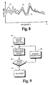
- a substantially optimum set of quantization resolutions may be obtained in a reiterative process such as that shown in Fig. 9.
- Step 81 obtains a set of initial quantization resolutions and step 82 applies a synthesis-filter spreading model to the initial resolutions to calculate the resultant noise levels.
- Step 83 compares the calculated resultant noise levels with the desired noise levels. If the results of the comparison are not acceptable, step 84 modifies the quantization resolutions appropriately and step 82 applies the noise-spreading model to the modified resolutions. For example, if the calculated resultant noise level for a signal component is too low, the quantization resolution for one or more signal components is made more coarse.
- step 85 quantizes signal components according to the quantization resolutions that provided the acceptable comparison.
- any set of initial quantization resolutions may be used; however, processing efficiency is generally improved by choosing initial resolutions that are close to the optimum values.
- One convenient choice for the initial resolutions are those resolutions that correspond to the desired noise levels.
- a quantization process may be carried out by a bit-allocation process that performs the following steps:
- a first simplified process uses a metric function to estimate the total noise level for each transform coefficient X ( k ) one at a time, starting with the lowest-frequency transform coefficient X (0), and determines whether noise spreading causes the total noise for that coefficient to exceed the desired noise level N ( k ). If the estimate indicates the total noise level for the current coefficient X ( k ) does not exceed the desired noise level, the process continues with the next higher-frequency transform coefficient.
- the coefficient that makes the largest contribution to the noise level of coefficient X ( k ) is identified and the gain factor g ( k ) for that coefficient is set to a prescribed value, say -144 dB which in one embodiment represents a compensation of 24 bits.
- the metric function is used to estimate the total noise level for coefficient X ( k ) that results with the adjusted bit allocation. If the estimated noise level still exceeds the desired noise level N ( k ), the coefficient making the next largest contribution to the noise level of coefficient X ( k ) is identified, its gain factor is set to the prescribed value, and the metric function is used again to estimate the new noise level. This continues until the estimated noise level is reduced to a level at or below the desired noise level.
- This program fragment is expressed in pseudo-code using a syntax that includes some syntactical features of the C, FORTRAN and BASIC programming languages.
- This program fragment and other program fragments described herein are not intended to be source code segments suitable for compilation but are provided to convey a few aspects of possible implementations.
- the routine Compensate is provided with array W that is the spreading matrix for a bank of synthesis filters, and array N specifying the desired noise spectrum.
- a main for-loop constitutes the remainder of the Compensate routine and carries out the compensation process for each of the low-frequency coefficients of interest.
- the Null function is invoked to initialize an array S to an empty or null state.
- L1 and L2 of the summation significantly affect the computational complexity of this process; the order of complexity for routine Compensate is (L1+L2) 2 .
- Computational efficiency can be improved by adjusting the values of L1 and L2 to limit the range of coefficients included in the calculation. The value for these limits can be determined empirically. In an alternative simplified process discussed below, these limits conform to the range of non-zero elements in a sparse version of array W.
- metric is positive and no compensation for noise spreading is needed. Therefore, if metric is positive, the remainder of the for-loop is skipped and processing continues for the next coefficient.
- the function Max is invoked to determine the coefficient k_max that makes the largest contribution to the noise for coefficient k. This is accomplished by finding the index i that corresponds to the maximum value for the product W[k, i] * g[i] * N[i] for i from 0 to M2-1 . This range for the index i includes all transform coefficients for the system. If desired, processing efficiency can be improved by limiting the search for the maximum product to a narrower range of coefficients. This range can be determined empirically. When the maximum contributor is found, the gain factor for k_max is assigned a prescribed value max_correction that corresponds to some maximum amount of compensation.
- the maximum amount of compensation is -144 dB, which corresponds to 24 bits.
- the estimated noise level for coefficient k When compensation has been applied to enough of the maximum contributors, the estimated noise level for coefficient k will be reduced to a value less than or equal to the desired noise level N[k] and the variable metric becomes positive. When this occurs, the while-loop terminates and processing continues by invoking the function Adjust to calculate a tentative new value g_new for the gain factors of the coefficients represented in array S, which correspond to the coefficients in set ⁇ S ⁇ discussed above. These new values are intended to optimize the level of compensation so that the estimated noise level is substantially equal to the desired noise level.
- g_new N ( k ) - ⁇ W ( k , i ) ⁇ g ( i ) ⁇ N ( i ) for i ⁇ S ⁇ ⁇ W ( k,i ) ⁇ N ( i ) for i ⁇ S ⁇
- Each gain factor for the coefficients represented in array S is set to the tentative value g_new if the tentative value is less than the current value of the respective gain factor.
- the main for-loop in the compensation process continues with the next transform coefficient until all coefficients of interest have been processed.
- One variation attains a significant reduction in computational complexity by recognizing that a few elements in a typical spreading matrix array W are significantly larger than all other elements, and that good performance can be realized even when many of these smaller elements are set to zero.
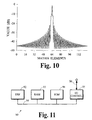
- Fig. 10 illustrates the values of the elements in the center row of a hypothetical spreading matrix.
- the dominant value in the center corresponds to the element on the main diagonal of the matrix.
- Elements on and near the main diagonal have values that are significantly larger than those elements that are away from the main diagonal.
- This characteristic allows the spreading matrix to be represented reasonably well by a sparse diagonal-band array and the values for L1 and L2 in the program fragment discussed above can be reduced to cover only the non-zero elements of the array. This characteristic also reduces the range over which a search is made for maximum contributors
- Another variation improves processing efficiency by eliminating the while-loop in the embodiment discussed above. Efficiency is improved by eliminating a reiterative process in which the maximum noise contributor is determined and a tentative new value for the gain factors is calculated.
- An embodiment of this variation is shown in the following program fragment:
- the routine Compensate is provided with the array W and the array N as described above.
- the main for-loop constitutes the remainder of the routine and carries out the compensation process for each of the low-frequency coefficients of interest.
- the variable metric is assigned a value estimating the noise level for the current coefficient k as described above.
- metric is positive and no compensation for noise spreading is needed. Therefore, if metric is positive, the remainder of the for-loop is skipped and processing continues for the next coefficient.
- the bit allocation for one or more transform coefficients in increased to account for noise spreading by finding the largest contributor k_max to the estimated noise and by applying a predetermined amount of correction to transform coefficient k_max and a few neighboring coefficients.
- the maximum contributor is determined by invoking the function Max, as described above, and the predetermined corrections are applied by reducing the values of the gain factors for coefficients -L1 to L2 by multiplying each gain factor by a respective value in the array comp.
- the gain factor g[k_max] may be reduced to indicate a 2-bit increase in allocation
- the gain factors g[k_max-1] and g[k_max+1] may be reduced to indicate a 1.5-bit increase in allocation
- the gain factors g[k_max-2] and g[k_max+2] may be reduced to indicate a 1-bit increase in allocation.
- the degree of predefined correction may be determined empirically for each application.
- the main for-loop in the compensation process continues with the next transform coefficient until all coefficients of interest have been processed.
- the spreading matrix, the gain factors and the noise levels are expressed in decibels; therefore, a function LogAdd is used to provide the sum of two logarithmic values.
- the noise contribution of coefficient j to coefficient k is represented by the expression w[k][j] + n[j], which represents the product of the desired noise level for coefficient j with a respective element of the spreading matrix.
- Each element k of array alloc represents the desired quantization noise in decibels for coefficient k.
- a second simplified process provides noise-spreading compensation in two steps.
- the first step determines an initial amount of compensation by taking each respective transform coefficient X ( k ) one at a time, starting with the lowest-frequency coefficient X (0), identifying the neighboring coefficients X ( j ) that make individual contributions to the estimated noise level of the respective coefficient that exceed the desired noise level N ( k ) for that coefficient, and determining the initial amount of compensation for those neighboring coefficients X ( j ) such that their respective individual contributions are reduced to the desired noise level.
- the second step reiteratively refines the compensation to bring the total noise contribution for each respective transform coefficient to the desired noise level.
- the routine Compensate is provided with the array W and the array N as described above.
- An array compN of compensation values is initialized from the array N of desired noise and a variable compOK is initialized so that the following while-loop executes at least once.
- the while-loop constitutes the remainder of the Compensate routine and carries out the compensation process in two steps.
- the loop first initializes the variable so that the while-loop will terminate unless excessive level noise is calculated in the second step.
- the portion of the routine that performs the first step initializes an array tempN of temporary calculations and executes a for-loop in which the noise contributions to each coefficient k is examined one at a time.
- a nested for-loop is used to calculate the estimated noise contribution W[k,j] * tempN[j] and determine if it is the maximum contribution calculated thus far. If not, the nested loop continues with the next coefficient j. If this estimated noise contribution is the largest level calculated thus far, the variables k_max and max_contrib are changed to reference the current coefficient j.
- the portion of the routine that performs the second step calculates an estimate of the total noise for each coefficient k and compares this estimate with the desired noise level N[k] . If the estimate exceeds the desired noise level, compensation compN[k] for the respective coefficient k is reduced by the same amount the desired noise level is exceeded by the estimated total noise.
- the variable compOK is set so that the first and second steps are performed again.
- the main while-loop continues until the first and second steps can be performed without causing the compOK variable to be set to False.
- this routine requires lower computational resources because the for-loop that identifies the maximum contributor max_contrib to the noise for a given coefficient j examines a narrow band of neighboring coefficients on either side of coefficient j from j-L1 to j+L2 , excluding the coefficient j itself, rather than examine the entire spectrum as is done in the program fragment discussed above.
- the present invention may be implemented in a wide variety of ways including software in a general-purpose computer system or in some other apparatus that includes more specialized components such as digital signal processor (DSP) circuitry coupled to components similar to those found in a general-purpose computer system.
- Fig. 11 is a block diagram of device 90 that may be used to implement various aspects of the present invention.
- DSP 92 provides computing resources.
- RAM 93 is system random access memory (RAM).
- ROM 94 represents some form of persistent storage such as read only memory (ROM) for storing programs needed to operate device 90 and to carry out various aspects of the present invention.
- I/O control 95 represents interface circuitry to receive and transmit audio signals by way of communication channel 96.
- Analog-to-digital converters and digital-to-analog converters may be included in I/O control 95 as desired to receive and/or transmit analog audio signals.
- bus 91 which may represent more than one physical bus; however, a bus architecture is not required to implement the present invention.
- additional components may be included for interfacing to devices such as a keyboard or mouse and a display, and for controlling a storage device having a storage medium such as magnetic tape or disk, or an optical medium.
- the storage medium may be used to record programs of instructions for operating systems, utilities and applications, and may include embodiments of programs that implement various aspects of the present invention.
- Software implementations of the present invention may be conveyed by a variety machine readable media such as baseband or modulated communication paths throughout the spectrum including from supersonic to ultraviolet frequencies, or storage media including those that convey information using essentially any magnetic or optical recording technology including magnetic tape, magnetic disk, and optical disc.
- machine readable media such as baseband or modulated communication paths throughout the spectrum including from supersonic to ultraviolet frequencies, or storage media including those that convey information using essentially any magnetic or optical recording technology including magnetic tape, magnetic disk, and optical disc.
- Various aspects can also be implemented in various components of computer system 90 by processing circuitry such as ASICs, general-purpose integrated circuits, microprocessors controlled by programs embodied in various forms of read-only memory (ROM) or RAM, and other techniques.
Landscapes
- Engineering & Computer Science (AREA)
- Physics & Mathematics (AREA)
- Computational Linguistics (AREA)
- Signal Processing (AREA)
- Health & Medical Sciences (AREA)
- Audiology, Speech & Language Pathology (AREA)
- Human Computer Interaction (AREA)
- Acoustics & Sound (AREA)
- Multimedia (AREA)
- Spectroscopy & Molecular Physics (AREA)
- Compression, Expansion, Code Conversion, And Decoders (AREA)
Applications Claiming Priority (3)
| Application Number | Priority Date | Filing Date | Title |
|---|---|---|---|
| US09/289,865 US6363338B1 (en) | 1999-04-12 | 1999-04-12 | Quantization in perceptual audio coders with compensation for synthesis filter noise spreading |
| US289865 | 1999-04-12 | ||
| PCT/US2000/009557 WO2000062434A1 (en) | 1999-04-12 | 2000-04-10 | Quantization in perceptual audio coders with compensation for synthesis filter noise spreading |
Publications (2)
| Publication Number | Publication Date |
|---|---|
| EP1177639A1 EP1177639A1 (en) | 2002-02-06 |
| EP1177639B1 true EP1177639B1 (en) | 2003-08-27 |
Family
ID=23113455
Family Applications (1)
| Application Number | Title | Priority Date | Filing Date |
|---|---|---|---|
| EP00923218A Expired - Lifetime EP1177639B1 (en) | 1999-04-12 | 2000-04-10 | Quantization in perceptual audio coders with compensation for synthesis filter noise spreading |
Country Status (13)
| Country | Link |
|---|---|
| US (1) | US6363338B1 (enExample) |
| EP (1) | EP1177639B1 (enExample) |
| JP (1) | JP4643019B2 (enExample) |
| KR (1) | KR100758215B1 (enExample) |
| AR (1) | AR024858A1 (enExample) |
| AT (1) | ATE248463T1 (enExample) |
| AU (1) | AU771869B2 (enExample) |
| CA (1) | CA2366560C (enExample) |
| DE (1) | DE60004814T2 (enExample) |
| HK (1) | HK1044235B (enExample) |
| MY (1) | MY120387A (enExample) |
| TW (1) | TW531986B (enExample) |
| WO (1) | WO2000062434A1 (enExample) |
Families Citing this family (51)
| Publication number | Priority date | Publication date | Assignee | Title |
|---|---|---|---|---|
| DE19947877C2 (de) * | 1999-10-05 | 2001-09-13 | Fraunhofer Ges Forschung | Verfahren und Vorrichtung zum Einbringen von Informationen in einen Datenstrom sowie Verfahren und Vorrichtung zum Codieren eines Audiosignals |
| US7734448B2 (en) * | 2000-01-10 | 2010-06-08 | Canning Francis X | Sparse and efficient block factorization for interaction data |
| US7720651B2 (en) * | 2000-09-29 | 2010-05-18 | Canning Francis X | Compression of interaction data using directional sources and/or testers |
| TW499672B (en) * | 2000-02-18 | 2002-08-21 | Intervideo Inc | Fast convergence method for bit allocation stage of MPEG audio layer 3 encoders |
| EP1297646B1 (en) * | 2000-06-12 | 2006-04-19 | BRITISH TELECOMMUNICATIONS public limited company | In-service measurement of perceived speech quality by measuring objective error parameters |
| US7945430B2 (en) | 2000-09-29 | 2011-05-17 | Canning Francis X | Compression and compressed inversion of interaction data |
| US7031955B1 (en) * | 2001-04-27 | 2006-04-18 | I2 Technologies Us, Inc. | Optimization using a multi-dimensional data model |
| SE0202159D0 (sv) | 2001-07-10 | 2002-07-09 | Coding Technologies Sweden Ab | Efficientand scalable parametric stereo coding for low bitrate applications |
| US6987889B1 (en) * | 2001-08-10 | 2006-01-17 | Polycom, Inc. | System and method for dynamic perceptual coding of macroblocks in a video frame |
| US6732071B2 (en) * | 2001-09-27 | 2004-05-04 | Intel Corporation | Method, apparatus, and system for efficient rate control in audio encoding |
| ATE288617T1 (de) | 2001-11-29 | 2005-02-15 | Coding Tech Ab | Wiederherstellung von hochfrequenzkomponenten |
| US7447631B2 (en) * | 2002-06-17 | 2008-11-04 | Dolby Laboratories Licensing Corporation | Audio coding system using spectral hole filling |
| US20040030555A1 (en) * | 2002-08-12 | 2004-02-12 | Oregon Health & Science University | System and method for concatenating acoustic contours for speech synthesis |
| SE0202770D0 (sv) | 2002-09-18 | 2002-09-18 | Coding Technologies Sweden Ab | Method for reduction of aliasing introduces by spectral envelope adjustment in real-valued filterbanks |
| US7376553B2 (en) * | 2003-07-08 | 2008-05-20 | Robert Patel Quinn | Fractal harmonic overtone mapping of speech and musical sounds |
| US20070067166A1 (en) * | 2003-09-17 | 2007-03-22 | Xingde Pan | Method and device of multi-resolution vector quantilization for audio encoding and decoding |
| US7539614B2 (en) * | 2003-11-14 | 2009-05-26 | Nxp B.V. | System and method for audio signal processing using different gain factors for voiced and unvoiced phonemes |
| CN1914669A (zh) * | 2004-01-28 | 2007-02-14 | 皇家飞利浦电子股份有限公司 | 使用复数值数据的音频信号解码 |
| DE102004009955B3 (de) * | 2004-03-01 | 2005-08-11 | Fraunhofer-Gesellschaft zur Förderung der angewandten Forschung e.V. | Vorrichtung und Verfahren zum Ermitteln einer Quantisierer-Schrittweite |
| US7512536B2 (en) * | 2004-05-14 | 2009-03-31 | Texas Instruments Incorporated | Efficient filter bank computation for audio coding |
| US7720236B2 (en) * | 2004-10-15 | 2010-05-18 | Lifesize Communications, Inc. | Updating modeling information based on offline calibration experiments |
| US7720232B2 (en) * | 2004-10-15 | 2010-05-18 | Lifesize Communications, Inc. | Speakerphone |
| US7826624B2 (en) * | 2004-10-15 | 2010-11-02 | Lifesize Communications, Inc. | Speakerphone self calibration and beam forming |
| US20060132595A1 (en) * | 2004-10-15 | 2006-06-22 | Kenoyer Michael L | Speakerphone supporting video and audio features |
| US8116500B2 (en) * | 2004-10-15 | 2012-02-14 | Lifesize Communications, Inc. | Microphone orientation and size in a speakerphone |
| US7970151B2 (en) * | 2004-10-15 | 2011-06-28 | Lifesize Communications, Inc. | Hybrid beamforming |
| US7903137B2 (en) * | 2004-10-15 | 2011-03-08 | Lifesize Communications, Inc. | Videoconferencing echo cancellers |
| US7760887B2 (en) * | 2004-10-15 | 2010-07-20 | Lifesize Communications, Inc. | Updating modeling information based on online data gathering |
| US7751572B2 (en) * | 2005-04-15 | 2010-07-06 | Dolby International Ab | Adaptive residual audio coding |
| US7991167B2 (en) * | 2005-04-29 | 2011-08-02 | Lifesize Communications, Inc. | Forming beams with nulls directed at noise sources |
| US7593539B2 (en) * | 2005-04-29 | 2009-09-22 | Lifesize Communications, Inc. | Microphone and speaker arrangement in speakerphone |
| US7970150B2 (en) * | 2005-04-29 | 2011-06-28 | Lifesize Communications, Inc. | Tracking talkers using virtual broadside scan and directed beams |
| US7974713B2 (en) * | 2005-10-12 | 2011-07-05 | Fraunhofer-Gesellschaft Zur Foerderung Der Angewandten Forschung E.V. | Temporal and spatial shaping of multi-channel audio signals |
| US7835904B2 (en) * | 2006-03-03 | 2010-11-16 | Microsoft Corp. | Perceptual, scalable audio compression |
| KR101393298B1 (ko) * | 2006-07-08 | 2014-05-12 | 삼성전자주식회사 | 적응적 부호화/복호화 방법 및 장치 |
| US8706507B2 (en) * | 2006-08-15 | 2014-04-22 | Dolby Laboratories Licensing Corporation | Arbitrary shaping of temporal noise envelope without side-information utilizing unchanged quantization |
| FR2912249A1 (fr) * | 2007-02-02 | 2008-08-08 | France Telecom | Codage/decodage perfectionnes de signaux audionumeriques. |
| CN102132494B (zh) * | 2008-04-16 | 2013-10-02 | 华为技术有限公司 | 通信方法和通信装置 |
| US20100106269A1 (en) * | 2008-09-26 | 2010-04-29 | Qualcomm Incorporated | Method and apparatus for signal processing using transform-domain log-companding |
| TWI556227B (zh) | 2009-05-27 | 2016-11-01 | 杜比國際公司 | 從訊號的低頻成份產生該訊號之高頻成份的系統與方法,及其機上盒、電腦程式產品、軟體程式及儲存媒體 |
| US11657788B2 (en) | 2009-05-27 | 2023-05-23 | Dolby International Ab | Efficient combined harmonic transposition |
| KR101599884B1 (ko) * | 2009-08-18 | 2016-03-04 | 삼성전자주식회사 | 멀티 채널 오디오 디코딩 방법 및 장치 |
| PL2489041T3 (pl) * | 2009-10-15 | 2020-11-02 | Voiceage Corporation | Jednoczesne kształtowanie szumu w dziedzinie czasu i w dziedzinie częstotliwości dla przekształcenia tdac |
| PL4451267T3 (pl) | 2009-10-21 | 2025-06-23 | Dolby International Ab | Nadpróbkowanie w banku filtrów połączonym z modułem transpozycji |
| US8958510B1 (en) * | 2010-06-10 | 2015-02-17 | Fredric J. Harris | Selectable bandwidth filter |
| US20120029926A1 (en) * | 2010-07-30 | 2012-02-02 | Qualcomm Incorporated | Systems, methods, apparatus, and computer-readable media for dependent-mode coding of audio signals |
| US9208792B2 (en) | 2010-08-17 | 2015-12-08 | Qualcomm Incorporated | Systems, methods, apparatus, and computer-readable media for noise injection |
| US9225310B1 (en) * | 2012-11-08 | 2015-12-29 | iZotope, Inc. | Audio limiter system and method |
| US10325584B2 (en) | 2014-12-10 | 2019-06-18 | Stmicroelectronics S.R.L. | Active noise cancelling device and method of actively cancelling acoustic noise |
| CN110870006B (zh) * | 2017-04-28 | 2023-09-22 | Dts公司 | 对音频信号进行编码的方法以及音频编码器 |
| US10886943B2 (en) * | 2019-03-18 | 2021-01-05 | Samsung Electronics Co., Ltd | Method and apparatus for variable rate compression with a conditional autoencoder |
Family Cites Families (9)
| Publication number | Priority date | Publication date | Assignee | Title |
|---|---|---|---|---|
| US4956871A (en) * | 1988-09-30 | 1990-09-11 | At&T Bell Laboratories | Improving sub-band coding of speech at low bit rates by adding residual speech energy signals to sub-bands |
| US5222189A (en) * | 1989-01-27 | 1993-06-22 | Dolby Laboratories Licensing Corporation | Low time-delay transform coder, decoder, and encoder/decoder for high-quality audio |
| JP2906646B2 (ja) * | 1990-11-09 | 1999-06-21 | 松下電器産業株式会社 | 音声帯域分割符号化装置 |
| EP0559348A3 (en) * | 1992-03-02 | 1993-11-03 | AT&T Corp. | Rate control loop processor for perceptual encoder/decoder |
| US5623577A (en) * | 1993-07-16 | 1997-04-22 | Dolby Laboratories Licensing Corporation | Computationally efficient adaptive bit allocation for encoding method and apparatus with allowance for decoder spectral distortions |
| SG66294A1 (en) * | 1993-07-16 | 1999-07-20 | Dolby Lab Licensing Corp | Computationally efficient adaptive bit allocation for encoding method and apparatus with allowance for decoder spectral distortions |
| EP0722225A3 (de) * | 1994-11-17 | 2000-06-07 | Deutsche Thomson-Brandt Gmbh | Audiosignalkodierung mittels Kurzzeitspektren und einem psychoakustischen Modell |
| JP2820117B2 (ja) * | 1996-05-29 | 1998-11-05 | 日本電気株式会社 | 音声符号化装置 |
| US5913191A (en) * | 1997-10-17 | 1999-06-15 | Dolby Laboratories Licensing Corporation | Frame-based audio coding with additional filterbank to suppress aliasing artifacts at frame boundaries |
-
1999
- 1999-04-12 US US09/289,865 patent/US6363338B1/en not_active Expired - Lifetime
-
2000
- 2000-04-10 EP EP00923218A patent/EP1177639B1/en not_active Expired - Lifetime
- 2000-04-10 DE DE60004814T patent/DE60004814T2/de not_active Expired - Lifetime
- 2000-04-10 WO PCT/US2000/009557 patent/WO2000062434A1/en not_active Ceased
- 2000-04-10 JP JP2000611392A patent/JP4643019B2/ja not_active Expired - Lifetime
- 2000-04-10 HK HK02105731.1A patent/HK1044235B/en unknown
- 2000-04-10 CA CA002366560A patent/CA2366560C/en not_active Expired - Lifetime
- 2000-04-10 AU AU43382/00A patent/AU771869B2/en not_active Expired
- 2000-04-10 KR KR1020017013052A patent/KR100758215B1/ko not_active Expired - Lifetime
- 2000-04-10 AT AT00923218T patent/ATE248463T1/de not_active IP Right Cessation
- 2000-04-10 AR ARP000101633A patent/AR024858A1/es active IP Right Grant
- 2000-04-11 MY MYPI20001499A patent/MY120387A/en unknown
- 2000-04-11 TW TW089106700A patent/TW531986B/zh not_active IP Right Cessation
Also Published As
| Publication number | Publication date |
|---|---|
| KR100758215B1 (ko) | 2007-09-12 |
| CA2366560C (en) | 2008-07-29 |
| AU4338200A (en) | 2000-11-14 |
| AU771869B2 (en) | 2004-04-01 |
| DE60004814D1 (de) | 2003-10-02 |
| US6363338B1 (en) | 2002-03-26 |
| CA2366560A1 (en) | 2000-10-19 |
| MY120387A (en) | 2005-10-31 |
| AR024858A1 (es) | 2002-10-30 |
| EP1177639A1 (en) | 2002-02-06 |
| DE60004814T2 (de) | 2004-07-01 |
| TW531986B (en) | 2003-05-11 |
| JP2002542648A (ja) | 2002-12-10 |
| KR20010112423A (ko) | 2001-12-20 |
| ATE248463T1 (de) | 2003-09-15 |
| JP4643019B2 (ja) | 2011-03-02 |
| HK1044235B (en) | 2003-12-24 |
| WO2000062434A1 (en) | 2000-10-19 |
| HK1044235A1 (en) | 2002-10-11 |
Similar Documents
| Publication | Publication Date | Title |
|---|---|---|
| EP1177639B1 (en) | Quantization in perceptual audio coders with compensation for synthesis filter noise spreading | |
| EP2216777B1 (en) | Audio coding system using spectral hole filling | |
| US6246345B1 (en) | Using gain-adaptive quantization and non-uniform symbol lengths for improved audio coding | |
| JP3297051B2 (ja) | 適応ビット配分符号化装置及び方法 | |
| US7627469B2 (en) | Audio signal encoding apparatus and audio signal encoding method | |
| EP0720148B1 (en) | Method for noise weighting filtering | |
| US20090198500A1 (en) | Temporal masking in audio coding based on spectral dynamics in frequency sub-bands | |
| EP1701452A1 (en) | System and method for masking quantization noise of audio signals | |
| US8032371B2 (en) | Determining scale factor values in encoding audio data with AAC | |
| EP1175670B1 (en) | Using gain-adaptive quantization and non-uniform symbol lengths for audio coding | |
| US9691398B2 (en) | Method and a decoder for attenuation of signal regions reconstructed with low accuracy | |
| AU2003237295B2 (en) | Audio coding system using spectral hole filling | |
| HK1141624B (en) | Audio coding system using spectral hole filling | |
| HK1141623B (en) | Audio decoding system using spectral hole filling | |
| HK1091024A1 (en) | Audio coding based on block grouping |
Legal Events
| Date | Code | Title | Description |
|---|---|---|---|
| PUAI | Public reference made under article 153(3) epc to a published international application that has entered the european phase |
Free format text: ORIGINAL CODE: 0009012 |
|
| 17P | Request for examination filed |
Effective date: 20010926 |
|
| AK | Designated contracting states |
Kind code of ref document: A1 Designated state(s): AT BE CH CY DE DK ES FI FR GB GR IE IT LI LU MC NL PT SE |
|
| AX | Request for extension of the european patent |
Free format text: AL;LT;LV;MK;RO;SI |
|
| GRAH | Despatch of communication of intention to grant a patent |
Free format text: ORIGINAL CODE: EPIDOS IGRA |
|
| GRAS | Grant fee paid |
Free format text: ORIGINAL CODE: EPIDOSNIGR3 |
|
| GRAA | (expected) grant |
Free format text: ORIGINAL CODE: 0009210 |
|
| AK | Designated contracting states |
Designated state(s): AT BE CH CY DE DK ES FI FR GB GR IE IT LI LU MC NL PT SE |
|
| PG25 | Lapsed in a contracting state [announced via postgrant information from national office to epo] |
Ref country code: IT Free format text: LAPSE BECAUSE OF FAILURE TO SUBMIT A TRANSLATION OF THE DESCRIPTION OR TO PAY THE FEE WITHIN THE PRESCRIBED TIME-LIMIT;WARNING: LAPSES OF ITALIAN PATENTS WITH EFFECTIVE DATE BEFORE 2007 MAY HAVE OCCURRED AT ANY TIME BEFORE 2007. THE CORRECT EFFECTIVE DATE MAY BE DIFFERENT FROM THE ONE RECORDED. Effective date: 20030827 Ref country code: NL Free format text: LAPSE BECAUSE OF FAILURE TO SUBMIT A TRANSLATION OF THE DESCRIPTION OR TO PAY THE FEE WITHIN THE PRESCRIBED TIME-LIMIT Effective date: 20030827 Ref country code: LI Free format text: LAPSE BECAUSE OF FAILURE TO SUBMIT A TRANSLATION OF THE DESCRIPTION OR TO PAY THE FEE WITHIN THE PRESCRIBED TIME-LIMIT Effective date: 20030827 Ref country code: CY Free format text: LAPSE BECAUSE OF FAILURE TO SUBMIT A TRANSLATION OF THE DESCRIPTION OR TO PAY THE FEE WITHIN THE PRESCRIBED TIME-LIMIT Effective date: 20030827 Ref country code: BE Free format text: LAPSE BECAUSE OF FAILURE TO SUBMIT A TRANSLATION OF THE DESCRIPTION OR TO PAY THE FEE WITHIN THE PRESCRIBED TIME-LIMIT Effective date: 20030827 Ref country code: AT Free format text: LAPSE BECAUSE OF FAILURE TO SUBMIT A TRANSLATION OF THE DESCRIPTION OR TO PAY THE FEE WITHIN THE PRESCRIBED TIME-LIMIT Effective date: 20030827 Ref country code: FR Free format text: LAPSE BECAUSE OF FAILURE TO SUBMIT A TRANSLATION OF THE DESCRIPTION OR TO PAY THE FEE WITHIN THE PRESCRIBED TIME-LIMIT Effective date: 20030827 Ref country code: CH Free format text: LAPSE BECAUSE OF FAILURE TO SUBMIT A TRANSLATION OF THE DESCRIPTION OR TO PAY THE FEE WITHIN THE PRESCRIBED TIME-LIMIT Effective date: 20030827 |
|
| REG | Reference to a national code |
Ref country code: GB Ref legal event code: FG4D |
|
| REG | Reference to a national code |
Ref country code: CH Ref legal event code: EP |
|
| REG | Reference to a national code |
Ref country code: IE Ref legal event code: FG4D |
|
| REF | Corresponds to: |
Ref document number: 60004814 Country of ref document: DE Date of ref document: 20031002 Kind code of ref document: P |
|
| PG25 | Lapsed in a contracting state [announced via postgrant information from national office to epo] |
Ref country code: SE Free format text: LAPSE BECAUSE OF FAILURE TO SUBMIT A TRANSLATION OF THE DESCRIPTION OR TO PAY THE FEE WITHIN THE PRESCRIBED TIME-LIMIT Effective date: 20031127 Ref country code: DK Free format text: LAPSE BECAUSE OF FAILURE TO SUBMIT A TRANSLATION OF THE DESCRIPTION OR TO PAY THE FEE WITHIN THE PRESCRIBED TIME-LIMIT Effective date: 20031127 Ref country code: GR Free format text: LAPSE BECAUSE OF FAILURE TO SUBMIT A TRANSLATION OF THE DESCRIPTION OR TO PAY THE FEE WITHIN THE PRESCRIBED TIME-LIMIT Effective date: 20031127 |
|
| PG25 | Lapsed in a contracting state [announced via postgrant information from national office to epo] |
Ref country code: ES Free format text: LAPSE BECAUSE OF FAILURE TO SUBMIT A TRANSLATION OF THE DESCRIPTION OR TO PAY THE FEE WITHIN THE PRESCRIBED TIME-LIMIT Effective date: 20031208 |
|
| PG25 | Lapsed in a contracting state [announced via postgrant information from national office to epo] |
Ref country code: PT Free format text: LAPSE BECAUSE OF FAILURE TO SUBMIT A TRANSLATION OF THE DESCRIPTION OR TO PAY THE FEE WITHIN THE PRESCRIBED TIME-LIMIT Effective date: 20040127 |
|
| NLV1 | Nl: lapsed or annulled due to failure to fulfill the requirements of art. 29p and 29m of the patents act | ||
| LTIE | Lt: invalidation of european patent or patent extension |
Effective date: 20030827 |
|
| REG | Reference to a national code |
Ref country code: CH Ref legal event code: PL |
|
| PG25 | Lapsed in a contracting state [announced via postgrant information from national office to epo] |
Ref country code: LU Free format text: LAPSE BECAUSE OF NON-PAYMENT OF DUE FEES Effective date: 20040410 |
|
| PG25 | Lapsed in a contracting state [announced via postgrant information from national office to epo] |
Ref country code: IE Free format text: LAPSE BECAUSE OF NON-PAYMENT OF DUE FEES Effective date: 20040412 |
|
| PG25 | Lapsed in a contracting state [announced via postgrant information from national office to epo] |
Ref country code: MC Free format text: LAPSE BECAUSE OF NON-PAYMENT OF DUE FEES Effective date: 20040430 |
|
| PLBE | No opposition filed within time limit |
Free format text: ORIGINAL CODE: 0009261 |
|
| STAA | Information on the status of an ep patent application or granted ep patent |
Free format text: STATUS: NO OPPOSITION FILED WITHIN TIME LIMIT |
|
| 26N | No opposition filed |
Effective date: 20040528 |
|
| EN | Fr: translation not filed | ||
| REG | Reference to a national code |
Ref country code: IE Ref legal event code: MM4A |
|
| PGFP | Annual fee paid to national office [announced via postgrant information from national office to epo] |
Ref country code: DE Payment date: 20190429 Year of fee payment: 20 Ref country code: FI Payment date: 20190429 Year of fee payment: 20 |
|
| PGFP | Annual fee paid to national office [announced via postgrant information from national office to epo] |
Ref country code: GB Payment date: 20190429 Year of fee payment: 20 |
|
| REG | Reference to a national code |
Ref country code: DE Ref legal event code: R071 Ref document number: 60004814 Country of ref document: DE |
|
| REG | Reference to a national code |
Ref country code: GB Ref legal event code: PE20 Expiry date: 20200409 |
|
| REG | Reference to a national code |
Ref country code: FI Ref legal event code: MAE |
|
| PG25 | Lapsed in a contracting state [announced via postgrant information from national office to epo] |
Ref country code: GB Free format text: LAPSE BECAUSE OF EXPIRATION OF PROTECTION Effective date: 20200409 |