EP1176684B1 - Multimedia connection box - Google Patents
Multimedia connection box Download PDFInfo
- Publication number
- EP1176684B1 EP1176684B1 EP01117925A EP01117925A EP1176684B1 EP 1176684 B1 EP1176684 B1 EP 1176684B1 EP 01117925 A EP01117925 A EP 01117925A EP 01117925 A EP01117925 A EP 01117925A EP 1176684 B1 EP1176684 B1 EP 1176684B1
- Authority
- EP
- European Patent Office
- Prior art keywords
- connection
- multimedia
- connection box
- box
- shield
- Prior art date
- Legal status (The legal status is an assumption and is not a legal conclusion. Google has not performed a legal analysis and makes no representation as to the accuracy of the status listed.)
- Expired - Lifetime
Links
Images


Classifications
-
- H—ELECTRICITY
- H02—GENERATION; CONVERSION OR DISTRIBUTION OF ELECTRIC POWER
- H02G—INSTALLATION OF ELECTRIC CABLES OR LINES, OR OF COMBINED OPTICAL AND ELECTRIC CABLES OR LINES
- H02G3/00—Installations of electric cables or lines or protective tubing therefor in or on buildings, equivalent structures or vehicles
- H02G3/02—Details
- H02G3/08—Distribution boxes; Connection or junction boxes
- H02G3/081—Bases, casings or covers
- H02G3/083—Inlets
-
- H—ELECTRICITY
- H01—ELECTRIC ELEMENTS
- H01R—ELECTRICALLY-CONDUCTIVE CONNECTIONS; STRUCTURAL ASSOCIATIONS OF A PLURALITY OF MUTUALLY-INSULATED ELECTRICAL CONNECTING ELEMENTS; COUPLING DEVICES; CURRENT COLLECTORS
- H01R24/00—Two-part coupling devices, or either of their cooperating parts, characterised by their overall structure
- H01R24/38—Two-part coupling devices, or either of their cooperating parts, characterised by their overall structure having concentrically or coaxially arranged contacts
- H01R24/40—Two-part coupling devices, or either of their cooperating parts, characterised by their overall structure having concentrically or coaxially arranged contacts specially adapted for high frequency
- H01R24/52—Two-part coupling devices, or either of their cooperating parts, characterised by their overall structure having concentrically or coaxially arranged contacts specially adapted for high frequency mounted in or to a panel or structure
- H01R24/525—Outlets
Definitions
- the present invention relates to a junction box according to the preamble of claim 1, and a shield terminal element according to claim 9 and a communication module according to claim 13 for use with this junction box and the use of a communication module with this junction box.
- junction boxes are from telecommunications and data transmission technology (See DE-C1-4234451 ), serve all forms of data communication such as video, audio, computer and telephone transmission and are used, inter alia, as surface-mounted or flush-mounted boxes in building construction.
- Both analog devices and ISDN devices for example for telephone, fax, modem, personal computer, etc., can be connected to these Socket Outlets to an S-BUS, which is terminated at its one end (customer side) with a terminating resistor of, for example, 100 ohms and at its other end (provider side) to a network termination device (NT + 2ab) is connected.
- This network termination device is in turn connected via a control box or exchange distributor with the local center.
- connection boxes for telecommunication or data transmission have, for example, 4-pole plug inserts, A6 inserts (6-pin), RJ45 inserts (8-pin) or RJ11 inserts (4-pin or 6-pin).
- These plug and socket outlets can be designed in a flush-mounted design and include a base plate with one or two inserts, a mounting plate and a cover.
- a flush-mounted inlet box is preferably provided, which usually has a substantially round cross section with an inner diameter of about 58 mm or a substantially rectangular Cross section with side lengths of about 58 mm x 58 mm.
- the plug and socket can also be designed in a surface-mounted version and includes, depending on the use, a cap or a cover frame with a front panel.
- junction boxes are also known from the television and radio engineering, ie HF technology, and in particular from the installations of coaxial cable networks.
- coaxial antenna sockets each have a shielded cable connection for a television and a radio receiver (IEC socket and IEC plug).
- IEC socket and IEC plug Such a junction box is for example from the DE 198 35 631 known.
- these are equipped with additional connections for a backward-compatible data communication, in particular an Internet connection and / or a telephone socket.
- Such multimedia junction boxes are preferably used in home and small office environments, among others. in apartments and houses, administrative buildings, hospitals and catering establishments. Electronic devices such as telephones, answering machines, televisions, video recorders and faxes, computers and Internet devices are increasingly being used there. Another development is in the use of remote-controlled household appliances, home security devices, lighting fixtures, etc. The cabling and networking of all these devices and installations requires considerable effort because separate doses must be installed for each of these services or applications.
- junction boxes that meet these needs in part, are already known in the art. These junction boxes have a metallic can body respectively a mounting element, in the bottom part of which is required for signal transmission electrical circuit. Sockets for the shielded and unshielded connectors, as well as terminals for attaching the coaxial cables to be connected, are mounted on this base part.
- the majority of the floor area or cross-sectional area of the junction box is required for the shielded coaxial connections, which is why the space above the floor space fitted with these coaxial connections must be used for the additional connection elements for communication technology. This leads to an undesirably high structure for the arrangement of the connectors and therefore to an undesirably large installation depth for the entire junction box.
- the main object of the present invention is to provide a junction box, which allows to use communication modules of known type in the simplest way and in combination with this can.
- a junction box with the features of claim 1 and in particular by a junction box, which comprises a closed metallic housing in which at least one coaxial connector is integrated, which metallic housing has a base area, the maximum half of the cross-sectional area claimed the junction box and which metallic housing is provided with a first adapter part for the attachment of at least one communication module.
- the cross-sectional area of the junction box is essentially limited by the space provided by the inlet box. Normally, this cross-sectional area will correspond to that of a standard installation box. It is therefore to be understood that the cross-sectional area of the junction box is not understood below to mean the cross-section of the space occupied by the modules used, but rather the cross-sectional area of the space usable for such modules.
- the insert modules for communication technology or the communication modules are arranged next to the metallic housing and, essentially on the same level.
- the metallic housing for the production of a mechanical and electrical interface is provided with at least one connection point for the tangential reception of a screen connection element.
- the advantages of the multimedia junction box according to the invention are immediately apparent to the person skilled in the art.
- these cans can be easily, quickly and inexpensively installed thanks to their large modularity and allow a variety of arbitrary arrangements to be made without much effort, so that the inventive multimedia junction box is very easy to install or user-friendly.
- an extension of the application possibilities can be achieved without much effort.
- this can simplifies the expansion of existing installations and enables optimal adaptation to customer needs.
- connection cables can be connected tangentially to the box, wherein it is meant that the connection cables are fed in a direction substantially tangential to the circumferential direction of the box direction, so that these cables of the box are fed under a maximum bending radius.
- the inventive arrangement leads to junction boxes with low installation depth, which is technically desirable to avoid, for example, sound and thermal bridges.
- FIG. 1 This consists essentially of a metallic mounting element 2 with a mounting collar 8 and a bottom part 3.
- the connection electronics respectively the electrical circuit for the connection is housed.
- Koaxialan gleichbuchsen 4, 5 are attached.
- a connection terminal 6 is provided, to which the required coaxial cables are connected.
- a socket 7 is also set up for the transmission of communication signals. This socket 7 is mounted substantially on this junction box and thus increases their overall height.
- FIG. 2 shows a view of a possible embodiment of an inventive multimedia junction box 11.
- a metallic housing 10 by means of three screws 12, 12 ', 12''attached to a mounting plate 9.
- three sockets 14, 15, 16 for the connection of shielded coaxial cables.
- a tangentially arranged shield connection element 17 allows the junction box with the house distribution system connect.
- This shield connection element 17 is designed such that it can be crimped on the one hand to a coaxial cable, and on the other hand in the metallic housing 10 can be inserted, so that this can make an electrically and mechanically stable connection with the metallic housing 10.
- this shield connection element 17 is arranged substantially tangentially to the circumferential direction of the metallic housing 10 on the box, so that a guide of the coaxial cable is possible with a maximum possible bending radius, ie that the cable has no kinks, respectively no places where the connected cable has to be bent in such a way that it falls below the permitted bending radius.
- a first adapter part 18, to which a communication module 19 can be fastened by means of a second adapter part 20, is attached to the metallic housing 10.
- This in FIG. 2 illustrated communication module comprises a terminal block 21 and two suitable for the data and communication RJ45 connection or contact sockets 22, 23.
- the inventive junction box 11 has a much lower overall height, with the overall height of the in FIG. 1 is meant with respect to the viewing plane in the vertical direction extending height.
- the contact socket 7 for the data and communication transmission offset in the vertical direction or above the sockets 4, 5 is arranged for the coaxial cable
- the inventive junction box 11 the contact sockets 19, 22 and the sockets 14, 15, 16 in essential at the same level lying, or lying side by side.
- This inventive arrangement makes it possible to create a multimedia junction box with a low total height of, for example, less than 30 mm, for example, 28.5 mm.
- Such a configuration has the particular advantage that the inventive multimedia junction box for installation in a standardized flush-mounted inlet box with 58 mm diameter or side length can be installed.
- the inventive multimedia junction box can be used in combination with existing, standardized inlet boxes.
- this is equipped with strain relief elements 24, 25. These strain relief elements 24, 25 can be moved transversely to the mounting plate 9 and are latched into this.
- FIG. 3 shows the inventive multimedia junction box 11 with an attached front panel 26 and a matching cover frame 27.
- This embodiment is suitable for flush mounting. It is understood that instead of the cover frame 27 also suitable for the surface mounting cap can be used, or that instead of a substantially square shaped front panel 26 and a circular front plate, respectively cylindrical cap can be used.
- FIG. 3 again clearly shows that connected to the metallic housing 10, for example, plugged sockets 22 and 23 for the data and communication transmission are in substantially the same plane as the integrated in the metallic housing 10 coaxial sockets 14, 15, 16th
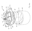
- FIG. 4 shows the inventive multimedia junction box 11 in an exploded view.
- the inventively designed metallic housing 10 in the bottom part of the required electronic and / or electrical circuit can be accommodated and in the inner part of the desired coaxial sockets 14, 15, 16 are integrated.
- the electronic or electrical circuit is shielded with a shield plate which forms the bottom of the metallic housing 10.
- This metallic housing 10 has at least one connection point 28 into which a shield connection element 17 can be inserted.
- the edge of the connection point 28 is designed such that with a ball joint shaped contact sleeve 29, a good mechanical and electrical connection can be made.
- the shield connection element 17 is provided on the cable side with a metallic sleeve 30 which is connected to the coaxial cable 31.
- a metallic sleeve 30 which is connected to the coaxial cable 31.
- an A-contact 32 is arranged, in which the soul 33 of the coaxial cable 31 can be inserted.
- the housing 10 has a base surface which occupies a maximum of half the cross-sectional or bottom surface of a standard installation box.
- the fastening plate 9 carries two strain relief elements 24, 25 which hold the shield connection elements 17 on the housing 10 in the locked state. It is understood that the mounting plate 9 is provided with openings 34 and 35 to mount them in a known manner.
- FIG. 5 shows a shield connection element 17 designed according to the invention with a core 33, which is connected to an A-contact 32.
- the shield connection element on the cable side an electrically conductive, in particular metallic crimp sleeve 30, which can be crimped onto an electrically conductive shield, in particular a metallic braid shield 38 of a coaxial cable 31.
- this shield connection element 17 has a metallic contact sleeve 29 which can be inserted into the connection point 28 of the metallic housing 10.
- the shape of this contact sleeve 29 is complementary to the shape of the connection point 28. This ensures a frictional and positive mechanical and a shielded electrical connection.
- the A-contact 32 is funnel-shaped on the cable side in order to be able to receive the core 33 of the coaxial cable 31 in a frictionally engaged manner.
- the contact sleeve 29 is provided with slots 36 to produce a resilient, non-positive and positive connection between the contact sleeve 29 and junction 28.
- the crimp barrel 30 may be slotted to facilitate crimping.
- a neck portion 37 is provided, via which the strain relief element 24 or 25 can be pushed.
- the shield connection element 17 is held in its position, respectively relieved of any tensile forces. It is understood that the shield connection element 17 does not necessarily need to be held with special strain relief elements 24, but can be secured to the metallic housing 10 by known means, in particular cable ties.
- FIG. 6 shows a further embodiment of a shield connection element 17, which, in contrast to the in FIG. 5 Shield connection element 17, a threaded sleeve 40 which is fixedly or flexibly connected to the contact sleeve 29, wherein the threaded sleeve 40 can be screwed onto the braid shield 38, so that an electrical screening effect between the braid shield 38 and the contact sleeve 29 is ensured.
- the braid shield 38 must be previously exposed and is advantageously covered over the outer insulation.
- FIG. 7 shows that in FIG. 6 Shroud connecting element 17 with contact sleeve 29, neck portion 37, threaded sleeve 40, braid shield 38 and cable sheath 41.
- the core 33 of the coaxial cable 31 is engaged by a U-shaped, prestressed, electrically conductive spring contact 42.
- This spring contact 42 is located downstream of the connection point 28 of the metallic housing 10.
- One of the legs of the U-shaped spring contact 42 is fixed to a base plate 43 (PCB or PWB).
- the gap-shaped opening of the spring contact 42 aligned in the illustrated arrangement with respect to the contact sleeve 29 is arranged with respect to the connection point 28 in such a way that the core 33 slides into the slot 28 during insertion of the shield connection element 17, so that a frictional and non-positive fit occurs , low-ohmic connection between the soul 33 and the spring contact 42 is formed.
- the spring contact 42 is preferably made of metal.
- the core 33 consists of a soft and the spring contact 42 of a relatively hard material. The high spring force of the spring contact 42 allows an electrical connection to the soul 33 with a very low contact resistance.
- FIG. 8 shows a further embodiment of a junction box 11, which comprises a metallic housing 10 with coaxial sockets 14, 15, 16, adapter part 18 and a mounting plate 9.
- a junction box 11 which comprises a metallic housing 10 with coaxial sockets 14, 15, 16, adapter part 18 and a mounting plate 9.
- port box 11 shown on the contact sleeve 29 and the correspondingly adapted configured connection point 28 are omitted by the stripped coaxial cable 31 is inserted directly into the connection point 28.
- the core 33 is exposed on the front side of the coaxial cable 31 and the braid shield 38 is placed on the surface of the outer jacket 41 resting.
- Behind the junction 28 is the in FIG. 7 arranged spring contact 42, in which the soul 33 is introduced.
- the junction box 11 includes a pivotally mounted in a bearing 46 fastening means 44, in particular a clamp, with screw 45 and ribs 47.
- the coaxial cable 31 is now mounted in the junction box 11 so that the soul 33 is inserted sufficiently deep into the spring contact 42 and the braid shield 38 to lie in the region of the ribs 47 comes.
- the fastener 44 is pivoted downwardly and fixedly connected to the metallic housing 10 by means of the screw 45, so that the coaxial cable 31 is slightly squeezed by the ribs 47, thereby forming a mechanical strain relief.
- the space in front of the connection point 28 may be provided with an electrically conductive shield 48 in order to better shield the transition point of the coaxial cable 31 against interference signals.
- the shield 48 is advantageously formed of a thin sheet metal, but may also consist of another electrical conductor, for example of an electrically conductive elastomer.
- the screw 45 can be released again at any time and the fastening means 44 can be opened so that the coaxial cable 31 can be replaced.
- An advantage of in FIG. 8 illustrated junction box 11 is the fact that for connecting the coaxial cable 31 no additional aids are required. It is sufficient to expose the core 33 and expose the braid shield 38 such that a conductive connection to the housing 10 can be formed.
- the connection point 28 is arranged in the housing 10 in such a way that the coaxial cable 31 can be fed to it substantially tangentially to the circumferential direction of the housing 10.
- FIG. 8 illustrated junction box 11 Another advantage of in FIG. 8 illustrated junction box 11 can be seen in the fact that coaxial cable 11 with different diameters can be connected without additional aids.
- FIG. 8 illustrated junction box 11 has two separate connections, each for a separate coaxial cable 31st
- FIG. 9 shows the two fixedly connected to the base plate 43 of the housing 10 spring contacts 42.
- the two Fastening means 44 are pivotally mounted in the metallic housing 10 via bearing pins 49 in the pivoting direction S.
- Each fastener 44 has an opening pin 50 which is arranged with respect to the spring contact 42 and configured adapted that this opening pin 50 engages when folding the fastener 44 in the space of the U-shaped spring contact 42 and thereby opens the spring contact, so that the soul 33 can be inserted without or with very little force in the spring contact 42 or pulled out of this.
- the in FIG. 9 illustrated opening pin 50 thus has the advantage that the soul 33, even if the spring contact 42 has a very high spring force, with little effort in the metallic housing is inserted.
- the opening pin 50 can also be electrically insulated and consist, for example, of an insulator or have an insulating surface coating.
- FIG. 10 shows the junction box 11 according to FIG. 8 together with a flush-mounted inlet box 51 with internal diameter D.
- the coaxial cable 31 is arranged substantially helically extending in the flush-mounted inlet box 51 and opens in a substantially tangential direction in the metallic housing 10 of the junction box 11.
- This arrangement has the advantage that the connection box 11 can be mounted with a relatively long coaxial cable section to be arranged in the flush-mounted inlet box 51, so that the connection box 11 is very comfortable, safe and can be mounted in a short time.
- the inner diameter D is preferably about 58 mm.
Abstract
Description
Die vorliegende Erfindung betrifft eine Anschlussdose gemäss Oberbegriff des Anspruchs 1, sowie ein Schirmanschlusselement gemäß Anspruch 9 und ein Kommunikationsmodul gemäß Anspruch 13 zur Verwendung mit dieser Anschlussdose und die Verwendung eines Kommunikationsmoduls mit dieser Anschlussdose.The present invention relates to a junction box according to the preamble of claim 1, and a shield terminal element according to claim 9 and a communication module according to claim 13 for use with this junction box and the use of a communication module with this junction box.
Derartige Anschlussdosen sind aus der Telekommunikationsund Datenübertragungstechnik (Siehe
Anschlussdosen sind auch aus der Fernseh- und Radiotechnik, d.h. HF-Technik, und insbesondere aus den Installationen von Koaxialkabelnetzen bekannt. So weisen beispielsweise Koaxial-Antennen-Steckdosen je einen abgeschirmten Kabelanschluss für ein Fernsehgerät und einen Radioempfänger (IEC-Buchse und IEC-Stecker) auf. Eine derartige Anschlussdose ist beispielsweise aus der
Derartige Multimedia-Anschlussdosen finden ihre Verwendung vorzugsweise im Heim- und Small-Office-Bereich, u.a. in Wohnungen und Häusern, Verwaltungsgebäuden, Spitälern und Gastronomie-Betrieben. Dort werden elektronische Geräte wie Telefon, Anrufbeantworter, Fernsehgeräte, Videorecorder sowie Fax, Computer und Internetgeräte zunehmend verwendet. Eine weitere Entwicklung zeichnet sich in der Verwendung von ferngesteuerten Haushaltgeräten, Home Security-Vorrichtungen, Beleuchtungskörper usw. ab. Die Verkabelung und Vernetzung all dieser Geräte und Installationen macht einen erheblichen Aufwand erforderlich, weil für jeden dieser Dienste respektive Anwendungen separate Dosen installiert werden müssen.Such multimedia junction boxes are preferably used in home and small office environments, among others. in apartments and houses, administrative buildings, hospitals and catering establishments. Electronic devices such as telephones, answering machines, televisions, video recorders and faxes, computers and Internet devices are increasingly being used there. Another development is in the use of remote-controlled household appliances, home security devices, lighting fixtures, etc. The cabling and networking of all these devices and installations requires considerable effort because separate doses must be installed for each of these services or applications.
Es besteht das Bedürfnis, insbesondere in Neubauten Verkabelungsmöglichkeiten zu schaffen, welche eine hohe Flexibilität und grosse Benutzerfreundlichkeit kostengünstig ermöglichen. Auch für bestehende Bauten und Umbauten besteht das Bedürfnis nach einer kostengünstigen und effizienten Erweiterung der vorhandenen Installationen.There is a need, especially in new buildings cabling to create, which a high Allow flexibility and ease of use at low cost. There is also a need for a cost-effective and efficient expansion of existing installations for existing buildings and conversions.
Anschlussdosen, welche diesen Bedürfnissen zum Teil nachkommen, sind dem Fachmann bereits bekannt. Diese Anschlussdosen weisen einen metallischen Dosenkörper respektive ein Montageelement auf, in dessen Bodenteil die für die Signalübertragung erforderliche elektrische Schaltung liegt. Auf diesem Bodenteil sind Buchsen für die geschirmten und ungeschirmten Steckverbindungen, sowie Anschlussklemmen für die Befestigung der anzuschliessenden Koaxialkabel angebracht. Bei diesen Multimedia-Anschlussdosen wird für die geschirmten Koaxialverbindungen der Grossteil der Bodenfläche respektive Querschnittsfläche der Anschlussdose beansprucht, weshalb für die zusätzlichen Anschlusselemente für die Kommunikationstechnik der Raum oberhalb des mit diesen Koaxialverbindungen bestückten Bodenraums verwendet werden muss. Dies führt zu einem unerwünscht hohen Aufbau für die Anordnung der Steckverbindungen und deshalb zu einer unerwünscht grossen Einbautiefe für die gesamte Anschlussdose.Junction boxes that meet these needs in part, are already known in the art. These junction boxes have a metallic can body respectively a mounting element, in the bottom part of which is required for signal transmission electrical circuit. Sockets for the shielded and unshielded connectors, as well as terminals for attaching the coaxial cables to be connected, are mounted on this base part. In the case of these multimedia junction boxes, the majority of the floor area or cross-sectional area of the junction box is required for the shielded coaxial connections, which is why the space above the floor space fitted with these coaxial connections must be used for the additional connection elements for communication technology. This leads to an undesirably high structure for the arrangement of the connectors and therefore to an undesirably large installation depth for the entire junction box.
Es ist Aufgabe der vorliegenden Erfindung, eine Anschlussdose zu schaffen, bei welcher die Einbautiefe respektive Bauhöhe der Dose minimiert ist und mit welcher eine Vielzahl von Anschlussvarianten in modularer Weise, d.h. ohne grossen Installationsaufwand ermöglicht werden kann.It is an object of the present invention to provide a junction box in which the installation depth or height of the can is minimized and with which a plurality of connection variants in a modular manner, i. can be made possible without great installation effort.
Es ist eine weitere Aufgabe der vorliegenden Erfindung, eine Anschlussdose zu schaffen, welche, gegenüber den heute bekannten Anschlussdosen, eine verbesserte HF-Dichtigkeit aufweist, d.h. rundum zuverlässig absgechirmt ist.It is a further object of the present invention to provide a junction box which, compared to the junction boxes known today, has an improved HF-tightness, ie is reliably shielded all around.
Es ist insbesondere Aufgabe der vorliegenden Erfindung, die mechanische und elektrische Schnittstelle für den Anschluss der Telekommunikations- und Datenübertragungskabel in einer Weise auszugestalten, sodass eine Anpassung an die Bedürfnisse des Anwenders in einfachster Weise möglich ist. Vorzugsweise soll auch beim Installieren der zulässige Biegeradius der verwendeten Kabel nicht unterschritten werden.It is a particular object of the present invention to design the mechanical and electrical interface for the connection of telecommunications and data transmission cables in a way that an adaptation to the needs of the user is possible in the simplest way. Preferably also when installing the allowable bending radius of the cable used should not be exceeded.
Bevorzugte Weiterbildungen der erfindungsgemässen Anschlussdose weisen die Merkmale der Unteransprüche 2 bis 8 auf.Preferred developments of the inventive junction box have the features of the
Es ist darüber hinaus Aufgabe der vorliegenden Erfindung, geschirmte und ungeschirmte Anschlusselemente für die Verwendung mit dieser Anschlussdose zu schaffen, welche mit dieser Anschlussdose mechanisch und elektrisch einwandfrei zusammenwirken.It is also an object of the present invention to provide shielded and unshielded connection elements for use with this junction box, which interact mechanically and electrically properly with this junction box.
Wesentliche Aufgabe der vorliegenden Erfindung ist es, eine Anschlussdose zu schaffen, welche es erlaubt, Kommunikationsmodule bekannter Art in einfachster Weise und in Kombination mit dieser Dose zu verwenden.The main object of the present invention is to provide a junction box, which allows to use communication modules of known type in the simplest way and in combination with this can.
Diese Aufgabe wird erfindungsgemäss durch eine Anschlussdose mit den Merkmalen des Anspruchs 1 gelöst und insbesondere durch eine Anschlussdose, welche ein geschlossenes metallisches Gehäuse umfasst, in welchem mindestens eine Koaxial-Anschlussbuchse integriert ist, welches metallische Gehäuse eine Grundfläche aufweist, die maximal die Hälfte der Querschnittsfläche der Anschlussdose beansprucht und welches metallische Gehäuse mit einem ersten Adapterteil für die Befestigung mindestens eines Kommunikationsmoduls versehen ist. Die Querschnittsfläche der Anschlussdose wird im wesentlichen durch den vom Einlasskasten zur Verfügung gestellten Raum begrenzt. Im Normalfall wird diese Querschnittsfläche derjenigen einer Normeinbaudose entsprechen. Es versteht sich also, dass im folgenden mit der Querschnittsfläche der Anschlussdose nicht der Querschnitt des durch die verwendeten Module beanspruchten Raums verstanden wird, sondern die Querschnittsfläche des für derartige Module nutzbaren Raums gemeint ist.This object is achieved according to the invention by a junction box with the features of claim 1 and in particular by a junction box, which comprises a closed metallic housing in which at least one coaxial connector is integrated, which metallic housing has a base area, the maximum half of the cross-sectional area claimed the junction box and which metallic housing is provided with a first adapter part for the attachment of at least one communication module. The cross-sectional area of the junction box is essentially limited by the space provided by the inlet box. Normally, this cross-sectional area will correspond to that of a standard installation box. It is therefore to be understood that the cross-sectional area of the junction box is not understood below to mean the cross-section of the space occupied by the modules used, but rather the cross-sectional area of the space usable for such modules.
Die Einsatzmodule für die Kommunikationstechnik bzw. die Kommunikationsmodule sind neben dem metallischen Gehäuse und, im wesentlichen auf gleicher Ebene angeordnet.The insert modules for communication technology or the communication modules are arranged next to the metallic housing and, essentially on the same level.
In einer besonderen Ausführungsform der erfindungsgemässen Anschlussdose ist das metallische Gehäuse für die Herstellung einer mechanischen und elektrischen Schnittstelle mit mindestens einer Anschlussstelle für die tangentiale Aufnahme eines Schirmanschlusselementes versehen.In a particular embodiment of the junction box according to the invention, the metallic housing for the production of a mechanical and electrical interface is provided with at least one connection point for the tangential reception of a screen connection element.
Die Vorteile der erfindungsgemässen Multimedia-Anschlussdose sind dem Fachmann unmittelbar ersichtlich. Insbesondere können diese Dosen dank ihrer grossen Modularität einfach, schnell und kostengünstig installiert werden und erlauben es, eine Vielzahl von beliebig wählbaren Anordnungen ohne grossen Aufwand herzustellen, sodass die erfindungsgemässe Multimedia-Anschlussdose sehr installationsfreundlich bzw. benutzerfreundlich ist. Es versteht sich, dass wegen der grossen Modularität eine Erweiterung der Anwendungsmöglichkeiten ohne grossen Aufwand zu erzielen ist. Darüber hinaus wird mit dieser Dose der Ausbau bestehender Installationen vereinfacht und eine optimale Anpassung an die Kundenbedürfnisse ermöglicht.The advantages of the multimedia junction box according to the invention are immediately apparent to the person skilled in the art. In particular, these cans can be easily, quickly and inexpensively installed thanks to their large modularity and allow a variety of arbitrary arrangements to be made without much effort, so that the inventive multimedia junction box is very easy to install or user-friendly. It is understood that because of the great modularity, an extension of the application possibilities can be achieved without much effort. In addition, this can simplifies the expansion of existing installations and enables optimal adaptation to customer needs.
Ein weiterer Vorteil der erfindungsgemässen Anschlussdose ist darin zu sehen, dass die geschirmten Anschlusskabel, respektive Koaxial-Anschlusskabel, tangential mit der Dose verbunden werden können, wobei gemeint ist, dass die Anschlusskabel in einer im wesentlichen tangential zur Umfangsrichtung der Dose verlaufenden Richtung zuführbar sind, sodass diese Kabel der Dose unter einem grösstmöglichen Biegeradius zuführbar sind.Another advantage of the inventive junction box is the fact that the shielded connection cable, respectively coaxial connection cable, can be connected tangentially to the box, wherein it is meant that the connection cables are fed in a direction substantially tangential to the circumferential direction of the box direction, so that these cables of the box are fed under a maximum bending radius.
Darüber hinaus führt die erfindungsgemässe Anordnung zu Anschlussdosen mit geringer Einbautiefe, was gebäudetechnisch erwünscht ist, um beispielsweise Schall- und Wärmebrücken zu vermeiden.In addition, the inventive arrangement leads to junction boxes with low installation depth, which is technically desirable to avoid, for example, sound and thermal bridges.
Im folgenden soll die vorliegende Erfindung anhand von Ausführungsbeispielen und mit Hilfe der Figuren näher erläutert werden. Es zeigen:
- Fig. 1
- eine aus dem Stand der Technik bekannte Multimedia-Anschlussdose für Koaxialkabel;
- Fig. 2
- eine erfindungsgemässe Multimedia-Anschlussdose;
- Fig. 3
- eine Multimedia-Anschlussdose gemäss
Fig. 2 mit montierter Abdeckplatte; - Fig. 4
- eine Multimedia-Anschlussdose gemäss
Fig. 2 , in Explosionsdarstellung, ohne Kommunikationsmodul; - Fig. 5
- eine Steckverbindung für den Anschluss eines Koaxialkabels an einen A-Kontakt einer erfindungsgemässen Multimedia-Anschlussdose;
- Fig. 6
- ein weiteres Ausführungsbeispiel eines Schirmanschlusselementes;
- Fig. 7
- das Schirmanschlusselement gemäss
Fig. 6 verbunden mit einem Federkontakt; - Fig. 8
- ein weiteres Ausführungsbeispiel einer erfindungsgemässen Anschlussdose;
- Fig. 9
- ein Detail der Anschlussdose gemäss
Fig. 8 ; - Fig. 10
- die Anschlussdose gemäss
Fig. 8 zusammen mit einem Unterputz-Einlasskasten.
- Fig. 1
- a known from the prior art multimedia junction box for coaxial cable;
- Fig. 2
- a multimedia junction box according to the invention;
- Fig. 3
- a multimedia junction box according
Fig. 2 with mounted cover plate; - Fig. 4
- a multimedia junction box according
Fig. 2 , in exploded view, without communication module; - Fig. 5
- a connector for connecting a coaxial cable to an A-contact of a multimedia junction box according to the invention;
- Fig. 6
- a further embodiment of a shield connection element;
- Fig. 7
- the shield connection element according to
Fig. 6 connected to a spring contact; - Fig. 8
- a further embodiment of an inventive junction box;
- Fig. 9
- a detail of the junction box according
Fig. 8 ; - Fig. 10
- the junction box according to
Fig. 8 together with a flush-mounted inlet box.
Die Vorteile dieser erfindungsgemässen Multimedia-Anschlussdose liegen insbesondere in ihrem einfachen und flachen Aufbau, ihrer vielfältigen Möglichkeiten zur Anpassung an die individuellen Bedürfnisse der Benutzer sowie ihrer vorzüglichen Abschirmqualitäten. Es versteht sich, dass die besondere Gestaltung ohne erfinderisches Dazutun geändert werden kann.The advantages of this multimedia junction box according to the invention are, in particular, its simple and flat structure, its many possibilities for adapting to the individual needs of the user and their excellent shielding qualities. It is understood that the particular design without inventive step can be changed.
Ein weiterer Vorteil der in
Es kann sich zudem als vorteilhaft erweisen, den Federkontakt 42 mit einem elektrischen Isolationsmittel, beispielsweise einem Kunststoff, derart zu umgeben, dass nur der Spalt, oder eventuell noch der Bereich für den Eingriff des Öffnungsstiftes 50, von aussen zugänglich ist.It may also prove to be advantageous to surround the
Claims (14)
- A multimedia connection box (11) with a box base part (3) with at least one connection point (28) for receiving a coaxial cable (31) and with at least one coaxial connection socket (14, 15, 16), characterised in that the connection box (11) comprises a closed, metal housing (10) in which at least one coaxial connection socket (14, 15, 16) is integrated, the metal housing (10) having a base surface which takes up at most half of the cross-sectional surface area of the connection box (11), and the metal housing (10) having a first adapter part (18) for connecting at least one communication module (19).
- A multimedia connection box according to Claim 1, characterised in that the metal housing (10) comprises the connection point (28) for the production of a mechanical and/or electrical interface.
- A multimedia connection box according to Claim 2, characterised in that the connection point (28) is arranged in the metal housing (10) such that a coaxial cable (31) can be connected to this connection point (28) in a direction extending substantially tangentially to the peripheral direction of the metal housing (10).
- A multimedia connection box according to one of the preceding claims, characterised in that the connection box (11) comprises at least one data communication module (19), the base surface of which takes up at most half of the cross-sectional surface area of the connection box (11).
- A multimedia connection box according to one of the preceding claims, characterised in that said box has a mounting plate (9) which is provided with at least one pull-relief element (24, 25).
- A multimedia connection box according to one of the preceding claims, characterised in that a spring contact (42) is arranged in the metal housing (10).
- A multimedia connection box according to Claim 6, characterised in that a fastening means (44) pivotably mounted in the housing (10) is arranged before the connection point (28).
- A multimedia connection box according to Claim 7, characterised in that the fastening means (44) has an opening pin (50) which is arranged with respect to the spring contact (42) such that the opening pin (50) opens the spring contact (42) upon pivoting-up of the fastening means (44).
- A shield connection element (17) for use with a multimedia connection box (11) according to Claim 1, characterised in that it is designed such that it cooperates mechanically and electrically with the connection point (28) of the connection box (11).
- A shield connection element according to Claim 9, characterised in that it has on the box side an electrically conductive contact bush (29), with which the mechanical and electrical contact with the connection point (28) can be brought about.
- A shield connection element according to one of Claims 9 or 10, characterised in that it has on the cable side an electrically conductive crimping sleeve (30) which can be crimped onto a shield means, in particular a braided shield (38) of a coaxial cable (31).
- A shield connection element according to one of Claims 9 or 10, characterised in that it has on the cable side a sleeve (40), in particular a threaded sleeve, which has an electrical connection to the shield means of the coaxial cable (31), and which is connected to the metal contact bush (29).
- A data and communication module (19) for use with a multimedia connection box (11) according to Claim 1, characterised in that it is provided with a second adapter part (20) which cooperates with the first adapter part (18) of the metal housing (10).
- Use of a data and communication module (19) according to Claim 13 in a multimedia connection box (11) according to Claim 1.
Applications Claiming Priority (2)
| Application Number | Priority Date | Filing Date | Title |
|---|---|---|---|
| CH14982000 | 2000-07-28 | ||
| CH14982000 | 2000-07-28 |
Publications (2)
| Publication Number | Publication Date |
|---|---|
| EP1176684A1 EP1176684A1 (en) | 2002-01-30 |
| EP1176684B1 true EP1176684B1 (en) | 2010-10-20 |
Family
ID=4565522
Family Applications (1)
| Application Number | Title | Priority Date | Filing Date |
|---|---|---|---|
| EP01117925A Expired - Lifetime EP1176684B1 (en) | 2000-07-28 | 2001-07-24 | Multimedia connection box |
Country Status (4)
| Country | Link |
|---|---|
| EP (1) | EP1176684B1 (en) |
| AT (1) | ATE485614T1 (en) |
| DE (1) | DE50115665D1 (en) |
| DK (1) | DK1176684T3 (en) |
Families Citing this family (3)
| Publication number | Priority date | Publication date | Assignee | Title |
|---|---|---|---|---|
| CH703304B1 (en) | 2010-06-01 | 2014-03-14 | Zidatech Ag | Junction box. |
| DE102014217481A1 (en) * | 2014-09-02 | 2016-03-03 | Fränkische Rohrwerke Gebr. Kirchner Gmbh & Co. Kg | connection unit |
| DE102017114982B3 (en) | 2017-07-05 | 2018-10-25 | Ecad Electronic Components And Devices Gmbh | Set of multimedia socket and switching pin |
Family Cites Families (3)
| Publication number | Priority date | Publication date | Assignee | Title |
|---|---|---|---|---|
| DE8708237U1 (en) * | 1987-06-11 | 1987-08-06 | Meyer A & H Leuchten Bueroelektrik Gmbh | |
| CA2017589C (en) * | 1990-05-25 | 1995-01-31 | William Nattel | Combination power and communication electrical wall terminal |
| DE4234451C1 (en) * | 1992-10-13 | 1994-04-21 | Metz Albert Blumberger Tel | Connector outlet for screened data transmission cables - has screened housing formed from metal die cast upper and lower sections which hold connection clamp carrying circuit board |
-
2001
- 2001-07-24 DK DK01117925.6T patent/DK1176684T3/en active
- 2001-07-24 DE DE50115665T patent/DE50115665D1/en not_active Expired - Lifetime
- 2001-07-24 EP EP01117925A patent/EP1176684B1/en not_active Expired - Lifetime
- 2001-07-24 AT AT01117925T patent/ATE485614T1/en active
Also Published As
| Publication number | Publication date |
|---|---|
| ATE485614T1 (en) | 2010-11-15 |
| DE50115665D1 (en) | 2010-12-02 |
| EP1176684A1 (en) | 2002-01-30 |
| DK1176684T3 (en) | 2011-01-24 |
Similar Documents
| Publication | Publication Date | Title |
|---|---|---|
| EP0809331B1 (en) | Multipolar plug system having a socket with at least one plug for electrical and mechanical connection of electric conductors | |
| EP1105947B1 (en) | System for transmitting messages via a low-voltage power supply network and adapter | |
| DE102009021594A1 (en) | Electrical connector and electrical connector | |
| WO2001035544A1 (en) | Communication system, especially for indoors | |
| EP0700126B1 (en) | Plug for a multiconductor cable | |
| EP2417675B1 (en) | Plug system housing for multi-core cables | |
| EP1176684B1 (en) | Multimedia connection box | |
| EP0447660A1 (en) | Connecting device for data transmission cables, particularly for a data network | |
| DE10053843C1 (en) | Socket for ethernet plug-in connection has Ethernet communications channel electrically screened from incorporated voltage supply contacts | |
| EP0865119B1 (en) | Junction box for a distribution system | |
| EP2568544B1 (en) | Multimedia socket | |
| DE3723987C2 (en) | ||
| DE19721532C2 (en) | Combination antenna socket for installation in a standardized surface or flush-mounted box | |
| EP2509159B1 (en) | Shielding | |
| EP0838881B1 (en) | Antenna outlet | |
| DE10339570B4 (en) | Antennensteckdose | |
| DE4345217C2 (en) | Connection cable to form a connection device for a data network | |
| DE19608876C2 (en) | Shielded junction box | |
| CH684042A5 (en) | Plug socket for connecting appts. to signal network, e.g. radio or TV to antenna | |
| DE4229705C2 (en) | Connector for high-frequency signals | |
| DE10121424C2 (en) | Connection unit for telecommunication and data networks | |
| EP0871251B1 (en) | Locking box | |
| DE19654861B4 (en) | Shielded junction box | |
| EP1249898A2 (en) | Coaxial connector with audible lock by electrical contacting | |
| EP2768089B1 (en) | Multimedia-Socket |
Legal Events
| Date | Code | Title | Description |
|---|---|---|---|
| PUAI | Public reference made under article 153(3) epc to a published international application that has entered the european phase |
Free format text: ORIGINAL CODE: 0009012 |
|
| AK | Designated contracting states |
Kind code of ref document: A1 Designated state(s): AT BE CH CY DE DK ES FI FR GB GR IE IT LI LU MC NL PT SE TR |
|
| AX | Request for extension of the european patent |
Free format text: AL;LT;LV;MK;RO;SI |
|
| 17P | Request for examination filed |
Effective date: 20020718 |
|
| AKX | Designation fees paid |
Free format text: AT BE CH CY DE DK ES FI FR GB GR IE IT LI LU MC NL PT SE TR |
|
| GRAP | Despatch of communication of intention to grant a patent |
Free format text: ORIGINAL CODE: EPIDOSNIGR1 |
|
| GRAS | Grant fee paid |
Free format text: ORIGINAL CODE: EPIDOSNIGR3 |
|
| GRAA | (expected) grant |
Free format text: ORIGINAL CODE: 0009210 |
|
| AK | Designated contracting states |
Kind code of ref document: B1 Designated state(s): AT BE CH CY DE DK ES FI FR GB GR IE IT LI LU MC NL PT SE TR |
|
| REG | Reference to a national code |
Ref country code: GB Ref legal event code: FG4D Free format text: NOT ENGLISH |
|
| REG | Reference to a national code |
Ref country code: CH Ref legal event code: EP Ref country code: CH Ref legal event code: NV Representative=s name: HANS ULRICH SEIFERT SEIFERT & PARTNER |
|
| REG | Reference to a national code |
Ref country code: IE Ref legal event code: FG4D Free format text: LANGUAGE OF EP DOCUMENT: GERMAN |
|
| REF | Corresponds to: |
Ref document number: 50115665 Country of ref document: DE Date of ref document: 20101202 Kind code of ref document: P |
|
| REG | Reference to a national code |
Ref country code: DK Ref legal event code: T3 |
|
| REG | Reference to a national code |
Ref country code: NL Ref legal event code: T3 |
|
| REG | Reference to a national code |
Ref country code: SE Ref legal event code: TRGR |
|
| REG | Reference to a national code |
Ref country code: IE Ref legal event code: FD4D |
|
| PG25 | Lapsed in a contracting state [announced via postgrant information from national office to epo] |
Ref country code: PT Free format text: LAPSE BECAUSE OF FAILURE TO SUBMIT A TRANSLATION OF THE DESCRIPTION OR TO PAY THE FEE WITHIN THE PRESCRIBED TIME-LIMIT Effective date: 20110221 |
|
| PG25 | Lapsed in a contracting state [announced via postgrant information from national office to epo] |
Ref country code: GR Free format text: LAPSE BECAUSE OF FAILURE TO SUBMIT A TRANSLATION OF THE DESCRIPTION OR TO PAY THE FEE WITHIN THE PRESCRIBED TIME-LIMIT Effective date: 20110121 |
|
| PG25 | Lapsed in a contracting state [announced via postgrant information from national office to epo] |
Ref country code: ES Free format text: LAPSE BECAUSE OF FAILURE TO SUBMIT A TRANSLATION OF THE DESCRIPTION OR TO PAY THE FEE WITHIN THE PRESCRIBED TIME-LIMIT Effective date: 20110131 Ref country code: IE Free format text: LAPSE BECAUSE OF FAILURE TO SUBMIT A TRANSLATION OF THE DESCRIPTION OR TO PAY THE FEE WITHIN THE PRESCRIBED TIME-LIMIT Effective date: 20101020 |
|
| PLBE | No opposition filed within time limit |
Free format text: ORIGINAL CODE: 0009261 |
|
| STAA | Information on the status of an ep patent application or granted ep patent |
Free format text: STATUS: NO OPPOSITION FILED WITHIN TIME LIMIT |
|
| 26N | No opposition filed |
Effective date: 20110721 |
|
| REG | Reference to a national code |
Ref country code: DE Ref legal event code: R097 Ref document number: 50115665 Country of ref document: DE Effective date: 20110721 |
|
| PG25 | Lapsed in a contracting state [announced via postgrant information from national office to epo] |
Ref country code: IT Free format text: LAPSE BECAUSE OF FAILURE TO SUBMIT A TRANSLATION OF THE DESCRIPTION OR TO PAY THE FEE WITHIN THE PRESCRIBED TIME-LIMIT Effective date: 20101020 |
|
| PG25 | Lapsed in a contracting state [announced via postgrant information from national office to epo] |
Ref country code: MC Free format text: LAPSE BECAUSE OF NON-PAYMENT OF DUE FEES Effective date: 20110731 |
|
| GBPC | Gb: european patent ceased through non-payment of renewal fee |
Effective date: 20110724 |
|
| REG | Reference to a national code |
Ref country code: FR Ref legal event code: ST Effective date: 20120330 |
|
| PG25 | Lapsed in a contracting state [announced via postgrant information from national office to epo] |
Ref country code: FR Free format text: LAPSE BECAUSE OF NON-PAYMENT OF DUE FEES Effective date: 20110801 |
|
| REG | Reference to a national code |
Ref country code: CH Ref legal event code: NV Representative=s name: THOMAS DAUB |
|
| REG | Reference to a national code |
Ref country code: DE Ref legal event code: R082 Ref document number: 50115665 Country of ref document: DE Representative=s name: DAUB UND KOLLEGEN, DE Ref country code: DE Ref legal event code: R082 Ref document number: 50115665 Country of ref document: DE Representative=s name: PATENT- UND RECHTSANWALTSKANZLEI DAUB, DE |
|
| PG25 | Lapsed in a contracting state [announced via postgrant information from national office to epo] |
Ref country code: GB Free format text: LAPSE BECAUSE OF NON-PAYMENT OF DUE FEES Effective date: 20110724 |
|
| PG25 | Lapsed in a contracting state [announced via postgrant information from national office to epo] |
Ref country code: CY Free format text: LAPSE BECAUSE OF EXPIRATION OF PROTECTION Effective date: 20101020 Ref country code: LU Free format text: LAPSE BECAUSE OF NON-PAYMENT OF DUE FEES Effective date: 20110724 |
|
| PG25 | Lapsed in a contracting state [announced via postgrant information from national office to epo] |
Ref country code: TR Free format text: LAPSE BECAUSE OF FAILURE TO SUBMIT A TRANSLATION OF THE DESCRIPTION OR TO PAY THE FEE WITHIN THE PRESCRIBED TIME-LIMIT Effective date: 20101020 |
|
| PGFP | Annual fee paid to national office [announced via postgrant information from national office to epo] |
Ref country code: NL Payment date: 20160720 Year of fee payment: 16 |
|
| REG | Reference to a national code |
Ref country code: CH Ref legal event code: PCAR Free format text: NEW ADDRESS: POSTFACH, 8058 ZUERICH-FLUGHAFEN (CH) |
|
| PGFP | Annual fee paid to national office [announced via postgrant information from national office to epo] |
Ref country code: CH Payment date: 20160721 Year of fee payment: 16 Ref country code: FI Payment date: 20160713 Year of fee payment: 16 Ref country code: DK Payment date: 20160720 Year of fee payment: 16 Ref country code: DE Payment date: 20160722 Year of fee payment: 16 |
|
| PGFP | Annual fee paid to national office [announced via postgrant information from national office to epo] |
Ref country code: SE Payment date: 20160720 Year of fee payment: 16 Ref country code: AT Payment date: 20160721 Year of fee payment: 16 |
|
| PGFP | Annual fee paid to national office [announced via postgrant information from national office to epo] |
Ref country code: BE Payment date: 20160720 Year of fee payment: 16 |
|
| REG | Reference to a national code |
Ref country code: DE Ref legal event code: R119 Ref document number: 50115665 Country of ref document: DE |
|
| REG | Reference to a national code |
Ref country code: DK Ref legal event code: EBP Effective date: 20170731 |
|
| REG | Reference to a national code |
Ref country code: CH Ref legal event code: PL |
|
| REG | Reference to a national code |
Ref country code: NL Ref legal event code: MM Effective date: 20170801 |
|
| REG | Reference to a national code |
Ref country code: SE Ref legal event code: EUG |
|
| REG | Reference to a national code |
Ref country code: AT Ref legal event code: MM01 Ref document number: 485614 Country of ref document: AT Kind code of ref document: T Effective date: 20170724 |
|
| PG25 | Lapsed in a contracting state [announced via postgrant information from national office to epo] |
Ref country code: LI Free format text: LAPSE BECAUSE OF NON-PAYMENT OF DUE FEES Effective date: 20170731 Ref country code: NL Free format text: LAPSE BECAUSE OF NON-PAYMENT OF DUE FEES Effective date: 20170801 Ref country code: CH Free format text: LAPSE BECAUSE OF NON-PAYMENT OF DUE FEES Effective date: 20170731 Ref country code: SE Free format text: LAPSE BECAUSE OF NON-PAYMENT OF DUE FEES Effective date: 20170725 Ref country code: DE Free format text: LAPSE BECAUSE OF NON-PAYMENT OF DUE FEES Effective date: 20180201 Ref country code: FI Free format text: LAPSE BECAUSE OF NON-PAYMENT OF DUE FEES Effective date: 20170724 |
|
| PG25 | Lapsed in a contracting state [announced via postgrant information from national office to epo] |
Ref country code: AT Free format text: LAPSE BECAUSE OF NON-PAYMENT OF DUE FEES Effective date: 20170724 |
|
| REG | Reference to a national code |
Ref country code: BE Ref legal event code: MM Effective date: 20170731 |
|
| PG25 | Lapsed in a contracting state [announced via postgrant information from national office to epo] |
Ref country code: DK Free format text: LAPSE BECAUSE OF NON-PAYMENT OF DUE FEES Effective date: 20170731 |
|
| PG25 | Lapsed in a contracting state [announced via postgrant information from national office to epo] |
Ref country code: BE Free format text: LAPSE BECAUSE OF NON-PAYMENT OF DUE FEES Effective date: 20170731 |