EP1176449A2 - Compact optical system and packaging for head mounted display - Google Patents
Compact optical system and packaging for head mounted display Download PDFInfo
- Publication number
- EP1176449A2 EP1176449A2 EP01480012A EP01480012A EP1176449A2 EP 1176449 A2 EP1176449 A2 EP 1176449A2 EP 01480012 A EP01480012 A EP 01480012A EP 01480012 A EP01480012 A EP 01480012A EP 1176449 A2 EP1176449 A2 EP 1176449A2
- Authority
- EP
- European Patent Office
- Prior art keywords
- optical system
- user
- microdisplay
- head mounted
- display unit
- Prior art date
- Legal status (The legal status is an assumption and is not a legal conclusion. Google has not performed a legal analysis and makes no representation as to the accuracy of the status listed.)
- Granted
Links
Images






Classifications
-
- G—PHYSICS
- G02—OPTICS
- G02B—OPTICAL ELEMENTS, SYSTEMS OR APPARATUS
- G02B27/00—Optical systems or apparatus not provided for by any of the groups G02B1/00 - G02B26/00, G02B30/00
- G02B27/01—Head-up displays
-
- G—PHYSICS
- G02—OPTICS
- G02B—OPTICAL ELEMENTS, SYSTEMS OR APPARATUS
- G02B27/00—Optical systems or apparatus not provided for by any of the groups G02B1/00 - G02B26/00, G02B30/00
- G02B27/01—Head-up displays
- G02B27/017—Head mounted
- G02B27/0172—Head mounted characterised by optical features
-
- G—PHYSICS
- G02—OPTICS
- G02B—OPTICAL ELEMENTS, SYSTEMS OR APPARATUS
- G02B27/00—Optical systems or apparatus not provided for by any of the groups G02B1/00 - G02B26/00, G02B30/00
- G02B27/01—Head-up displays
- G02B27/017—Head mounted
- G02B27/0176—Head mounted characterised by mechanical features
-
- G—PHYSICS
- G02—OPTICS
- G02B—OPTICAL ELEMENTS, SYSTEMS OR APPARATUS
- G02B27/00—Optical systems or apparatus not provided for by any of the groups G02B1/00 - G02B26/00, G02B30/00
- G02B27/01—Head-up displays
- G02B27/0101—Head-up displays characterised by optical features
- G02B2027/0132—Head-up displays characterised by optical features comprising binocular systems
-
- G—PHYSICS
- G02—OPTICS
- G02B—OPTICAL ELEMENTS, SYSTEMS OR APPARATUS
- G02B27/00—Optical systems or apparatus not provided for by any of the groups G02B1/00 - G02B26/00, G02B30/00
- G02B27/01—Head-up displays
- G02B27/017—Head mounted
- G02B2027/0178—Eyeglass type
-
- G—PHYSICS
- G02—OPTICS
- G02B—OPTICAL ELEMENTS, SYSTEMS OR APPARATUS
- G02B5/00—Optical elements other than lenses
- G02B5/30—Polarising elements
Definitions
- the present invention relates generally to compact optical systems and, more particularly, to compact optical systems for use in display devices, for example, personal devices such as wearable personal computer systems, head mounted displays, portable telephones and the like.
- Virtual image displays combine magnifying optics with a small image panel to provide the viewer with a virtual image capable of displaying large amounts of information.
- Such displays have found application in so called head mounted displays and are used in conjunction with a computer-based device for a variety of applications.
- the computer-based device includes processing and display driver circuitry for generating the image signal to be displayed via the optics and image panel.
- FIG. 1 illustrates a head mounted virtual display unit 10 which rests on the users head and face in a manner similar to that of a pair of eye glasses. The user views virtual images through the display portion 12. Nose bridge 14 and side supports 16 serve to provide support for the display while on the users head and face.
- the unit 10 may be connected to a computer via connector 18. It is known that such a unit is cumbersome and permits the wearer to see substantially nothing other than the display screen. That is, the user is unable to view his immediate environment.
- WO 95/11473 Such a head mounted virtual display is disclosed in an international patent application identified as WO 95/11473.
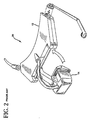
- FIG. 2 illustrates a head mounted monocular virtual display unit 20.
- the support structure 12 is positioned on a users head and the display portion 14 comes down in the users field of vision. This design is also known to be cumbersome and likely to obstruct the users surrounding view.
- Such a head mounted monocular virtual display is also disclosed in a the international patent application identified as WO 95/11473.
- the present invention provides an optical system design for use in display devices such as, for example, a head mounted virtual image display, that remedies defects exhibited by conventional designs, e.g., prohibitive size and weight, obstructed view, etc.
- a novel design for example, makes possible wearable computer systems of greater convenience and acceptability to a wide range of users.
- the optical system comprises: a beam splitting prism positioned proximate to the microdisplay; a field lens positioned between the beam splitting prism and the microdisplay; a negative lens positioned between the field lens and the beam splitting prism; a reflective lens positioned proximate to the beam splitting prism, on a side of the beam splitting prism opposite the microdisplay; and a quarter wave plate positioned between the reflective lens and the beam splitting prism; wherein the beam splitting prism, the field lens, the negative lens, the reflective lens and the quarter wave plate are arranged such that the image signal, linearly polarized in accordance with the microdisplay: (a) passes through the field lens and the negative lens; (b) enters the beam splitting prism substantially passing through a polarizing surface of the beam splitting prism; (c) passes through the quarter wave plate becoming circularly polar
- the display unit is compact in size and weight, and incorporates a high performance optical system, such as the optical system described above, offering a clear see-through capability.
- a sliding light shield may be incorporated for those instances when see-through capability is not desired.
- a focus adjustment may be incorporated to permit the focusing of the image, for example, at a distance of approximately 18 inches to infinity.
- An adjustable headband may be incorporated that adapts to fit the users head.
- a flexible boom structure may be incorporated to facilitate fine positional adjustment of the optical assembly.
- a slider and ball joint mechanism may also be incorporated to facilitate positional adjustment of the optical assembly.
- a built-in microphone may be incorporated to enable speech input by the user.
- the head mounted virtual image display unit may be used comfortably in conjunction with eye or safety glasses, and provides a useful image to the user without blocking his view of the surrounding environment.
- the unit is designed to have a pleasing appearance so as to greatly enhance user acceptability.
- a head mounted virtual image display unit may be combined with a computer-based device.
- the computer-based device may generate and provide an electrical signal to a microdisplay associated with the display unit for use in generating the image signal to be viewed by the user.
- the combination advantageously forms a portable computer system.
- an optical system design of the present invention will be explained below in the context a head mounted virtual image display unit and wearable computer.
- the present invention is not limited to this or any particular display application. Rather, the invention is more generally applicable to any suitable display application in which it is desirable to utilize a compact optical system for displaying images which may be incorporated into a device used in the application.
- Such devices may be, for example, personal devices such as wearable personal computers, head mounted displays, portable telephones and the like.
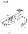
- FIGs. 3A and 3B a head mounted virtual display unit 10 and computer-based device 20 according to one embodiment of the present invention are shown.
- a cable 30 is provided for electrically coupling the computer-based device 20 with the head mounted virtual display unit 10.
- FIGs. 3A and 3B illustrate the same head mounted virtual display unit 10, but from opposing views.
- the computer-based device 20 preferably has a small form factor, e.g., pocket-sized, and is lightweight. It may also preferably have a clip for attachment to a user's belt or pocket.
- the wearable computer may include all or most of the typical components available in a personal computer, laptop computer, personal digital assistant or the like, e.g., a processor (e.g., CPU), fixed memory, removable memory, display driver circuitry, external network (e.g., Internet) connection device, application software, etc.
- a processor e.g., CPU
- fixed memory e.g., fixed memory
- removable memory e.g., removable memory
- display driver circuitry e.g., Internet connection device
- application software e.g., etc.
- the head mounted virtual display unit 10 comprises: an optical module 100; a flexible boom 200; an adjustment pod 300; an earpiece 400; and a head band 500.
- the optical module 100 comprises an optical system, a focus mechanism, a sliding light shield and an integrated microphone.
- the flexible boom 200 enables fine positional control of the optical module 100 in front of the user's eye.
- a metal or plastic, spiral-wound gooseneck tubing may be used as the flexible boom. Such tubing is well known and commercially available.
- the adjustment pod 300 preferably contains a combination sliding and ball joint mechanism for controlling of the boom position and angle. This embodiment will be explained in more detail below in the context of FIG. 10.
- the earpiece 400 is shown attached to the pod 300 by means of a connecting wire. Alternatively, it may be attached to the pod 300 with its output directed towards the user's ear, or attached on a swing down lever from the pod 300.
- the headband 500 is shown with adjustment tabs 502 and head grips 504.
- the headband is normally worn around the back of the head, however, alternate arrangements are possible. For example, the band may go over the top of the head or, alternatively, the pod 300 may be attached to a helmet (not shown).
- the flexible boom 200 and adjustment pod 300 permit the user to move the optical module 100 into and out of the field of view of, in this case, his right eye.
- the unit 10 may be configured such that the optical module 100 is viewed by a wearer's left eye. In such case, the unit 10 can be turned over to be used by the left eye.
- the unit 10 may be configured to include two separate display portions, that is, one for the right eye and one for the left eye.
- the combination of the display unit 10 and the computer-based device 20 permits a user to view visual data generated in accordance with the device 20, e.g., from application software, web browser, etc.
- the visual information is provided to the display via cable 30.
- the earpiece 400 permits a user to listen to audio data generated in accordance with the device 20.
- the microphone (shown in FIG. 8) in the optical module 100 permits a user to input voice commands to the computer.
- FIGs. 3A and 3B illustrate a light weight wearable computer system comprising a light weight head mounted display unit containing a compact optical system used in conjunction with a pocket sized, wearable computer. Since the optical system is attached to the user's head by means of a light weight boom or band structure, such as shown, this enables a total head mounted display weight of approximately two ounces or less to be achieved.
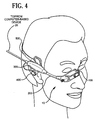
- FIG. 4 illustrates an artistic rendering of a head mounted virtual display unit 10 according to the present invention as may be worn by a user.
- the optical module 100 may be advantageously moved into the field of view of the user's right eye or left eye. It is small so as to be unobtrusive and allows an undistorted view through the optical system to the outside world. When the display is turned on, there is enough light that the display can be seen clearly against the surroundings.
- optical system for use in the optical module 100 will now be described. It is to be understood, however, that the inventive optical system design may be used in accordance with devices other than the wearable computer system illustrated in FIGs. 3A and 3B. Given their compact form factors and ability to display high quality optical images, the optical system of the invention is suitable for a vast number of applications. One of ordinary skill in the art will realize various other implementations and applications with which such an inventive optical system may be employed.
- the optical system of the invention provides optics with folded light paths which are "on-axis” optics rather than “free form” optics.
- the optical system is able to provide the advantages and features described herein, as well as others that one or ordinary skill in the art will realize given the inventive teachings herein.
- on-axis and free form we mean the following.
- the bundle of rays passes through the lens cluster about this axis and may be well imaged by the lens. Examples of systems might be a camera, microscope, binoculars.
- the bundle of rays may cluster about a line tilted with respect to the lens; this would be "off-axis" imaging.
- the typical spherical lens is symmetric about the optic axis.
- Yet other systems are not radially symmetric and do not have a clear optical axis as defined above, yet may still perform an imaging function. We generally call them “free form” optics.
- this optical system is preferably the optical system that is employed in the optical module 100.
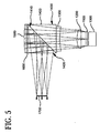
- a light source 1000 typically a cluster of red, green and blue light emitting diodes (LEDs)
- LEDs light emitting diodes
- the microdisplay is a transmissive type microdisplay.
- Transmissive microdisplays that may be used in accordance with the invention are available, for example, from Kopin of Taunton, MA. It is to be appreciated that the transmissive microdisplay may be replaced with an emissive microdisplay wherein the light source is internal to the microdisplay.
- Emissive microdisplays that may be used in accordance with the invention are available, for example, from Planar of Beaverton, OR. Also, the microdisplay may be a reflective type microdisplay. Reflective microdisplays that may be used in accordance with the invention are available, for example, from Colorado Microdisplay of Boulder, CO.
- the microdisplay creates an image in response to electrical signals applied to the display.
- the electrical signals may, for example, be provided to the microdisplay from the computer-based device 20 (FIGs. 3A and 3B).
- This image is viewed by means of a field lens 1200, a negative lens 1300, a beam splitting prism 1400, a quarter wave plate 1600 and a reflective lens 1500.
- a negative lens includes one or more outer surfaces having a concave form, as compared to a positive lens which includes one or more outer surfaces having a convex form. Light from the display is linearly polarized and travels through lenses 1200 and 1300 entering the prism 1400.
- the polarization of the light is such that the light is substantially transmitted through a polarizing surface 1410 of prism 1400.
- the light then passes through the quarter wave plate 1600 and becomes circularly polarized.
- the reflective lens 1500 has a reflective coating (e.g., metallic or dielectric reflective material) at its curved surface that reflects light back towards the quarter wave plate 1600.
- the quarter wave plate 1600 Upon passing through the quarter wave plate 1600 a second time, the light once again becomes linearly polarized, however, its polarization direction has now been rotated by 90 degrees.
- the light reenters the prism 1400 and is now substantially reflected by polarizing surface 1410.
- the light leaves the prism 1400 and approaches the exit pupil 1700 of the optical system.
- the optical system exit pupil 1700 is where the user normally positions their eye to view the virtual image of the microdisplay 1100.
- the light from the microdisplay 1100 forms a virtual image at the exit pupil 1700, and that the image is of high quality and substantially free of aberration. That is, the virtual image is essentially free of astigmatism, essentially free of lateral distortion, and essentially free of lateral color aberration.
- This high performance is achieved by combining the field lens 1200, the negative lens 1300, the prism 1400, the quarter wave plate 1600 and the reflective lens 1500 in the arrangement shown and by proper selection of materials for these elements.
- the negative lens 1300 material is chosen to work in combination with the field lens 1200 and reflective lens 1500 to essentially eliminate lateral color aberration.
- the preferred design parameters associated with these lens, as well as the other elements of the optical module, will be given below in the context of FIG. 7.
- FIGs. 6A through 6C show three respective graphs of the optical system performance of the optics shown in FIG. 5.
- FIG. 6A a graph of astigmatism versus field position is shown. It is apparent that image field is flat within 0.016 millimeters (mm), and that there is less than 0.005 mm of astigmatism between the sagital and tangential directions. This means the image is essentially perfectly flat and essentially without astigmatism.
- FIG. 6B shows a graph of distortion versus field position. From this graph, we see that the optical system has less than 0.2 percent distortion across the field. For those skilled in the art, this means the image is essentially distortion free.
- FIG. 6C shows a graph of the lateral color versus field position.
- the microdisplay of a preferred embodiment has a pixel pitch of approximately 0.012 mm. Therefore, the optical system is essentially free of lateral color aberration.
- FIG. 7 illustrates a table of design parameters of an optical system according to a preferred embodiment of the present invention.
- the table gives the surface number (column A), the surface radius or curvature (column B), the center thickness of surface (column C), the aperture radius of surface (column D) and the material (column E) for each optical element in the system.
- SRF refers to "surface;
- OBJ refers to "object position;
- AST refers to "aperture stop;
- IMS refers to "image surface;” and BK7 and SF1 are industry standard glass types. It also gives the spacing between the elements.
- the surfaces listed in the table are surfaces of the components (e.g., beam splitting prism, field lens, etc.) of the optical system shown in FIG. 5.
- the correspondence between the components of FIG. 5 and the surfaces is denoted down the left hand side of FIG. 7 by the bracket and corresponding reference numeral of the component from FIG. 5.
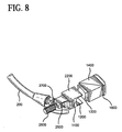
- FIG. 8 an integrated focus mechanism and placement of an integrated microphone in a head mounted virtual display according to an embodiment of the present invention is shown. As previously mentioned, these components are housed in the optical module 100 shown in FIGs. 3A and 3B. It is to be understood that FIG. 8 illustrates the focus mechanism and microphone with the outer casing (housing) of the optical module 100 removed.
- a compact carriage mechanism translates the field lens 1200, microdisplay 1100 and LED backlight 1000, shown in FIG. 5, such as to focus the virtual image at a distance of approximately 18 inches to infinity.
- the field lens 1200, the microdisplay 1100 and the backlight 1000 are mounted in the movable carriage 2200.
- the carriage 2200 is translated along the optical axis by means of a screw 2500 and knob 2600.
- Other conventional translation actuators arrangements may be employed.
- a motion of ⁇ 1 mm of the carriage 2200 relative to the beam splitting prism 1400 is sufficient to adjust the image focus over the desired range.
- the negative lens 1300, the beam splitting prism 1400, the quarter wave plate 1600 and the reflective lens 1500 remain fixed inside the housing of the optical module.
- FIG. 8 illustrates the placement of a compact microphone 2700.
- the microphone may be of the directional type. It is pointed towards the users face and away from the surrounding environment such as to pick up the voice of the user. It is to be appreciated that wiring for the microphone and for the optical system may be run through the flexible boom 200.
- the components in the optical module, as well as the earpiece 400 may be coupled to a computer-based device 20 via a cable 30 (FIGs. 3A and 3B).
- FIGs. 9A and 9B illustrate a sliding light shield in the open and closed positions, respectively, on a head mounted virtual image display according to an embodiment of the present invention.
- FIGs. 9A and 9B show a detailed view of the optical module 100 with a light shield integrated with the housing of the optical module.
- a light shield 3200 is shown in the open position (see-through mode).
- the beam splitting prism 1400 is visible in FIG. 9A with the light shield 3200 in the open position.
- the light shield 3200 is shown in the closed position, thus blocking or substantially blocking the background light.
- the light shield 3200 may be slid by the user along the direction indicated by arrow A when it is desired to reduce or eliminate the background light. It is to be appreciated that the external light modifying shield may be opaque, partially opaque, colored or polarizing as desired by the application being executed in accordance with the virtual display system.
- FIG. 10 illustrates headband and pod/boom adjustment mechanisms on a head mounted virtual display according to an embodiment of the present invention.
- FIG. 10 shows a detail of the pod/boom adjustment mechanism.
- the adjustment pod 300 comprises a base portion 4100 having a channel 4110 formed therein. Inside the channel 4110 is fitted a slider mechanism 4200 which is capable of sliding back and forth the length of the channel, as denoted by the direction arrow 4400.
- Small circular indentations 302 (visible in FIG. 3B) mate with one or more corresponding protrusions on the inner side of the slider mechanism (not shown) to allow the slider mechanism, and thus the optical module 100, to remain in a desired position.
- the pod assembly comprises a ball joint 4300 pivotably fitted in the slider mechanism 4200.
- the pivotable ball joint 4300 allows the pod assembly, and thus the optical module 100, to rotate, as denoted by the direction arrows 4500 and 4600.
- the flexible boom 200 also allows the optical module to be moved in any of the directions denoted by arrows 4400, 4500 and 4600.
Landscapes
- Physics & Mathematics (AREA)
- General Physics & Mathematics (AREA)
- Optics & Photonics (AREA)
- Eyeglasses (AREA)
- Surface Treatment Of Optical Elements (AREA)
- Optical Elements Other Than Lenses (AREA)
- Lenses (AREA)
- Polarising Elements (AREA)
Abstract
Description
Claims (18)
- A compact optical system for directing an image signal for viewing by a user, the image signal being generated in accordance with a microdisplay, the system comprising:wherein the beam splitting prism, the field lens, the negative lens, the reflective lens and the quarter wave plate are arranged such that the image signal, linearly polarized in accordance with the microdisplay: (a) passes through the field lens and the negative lens; (b) enters the beam splitting prism substantially passing through a polarizing surface of the beam splitting prism; (c) passes through the quarter wave plate becoming circularly polarized; (d) reflects at a surface of the reflective lens back toward the quarter wave plate passing through the quarter wave plate a second time becoming linearly polarized with a polarization direction rotated by 90 degrees with respect to an original linear polarization direction associated with the image signal; and (e) reenters the beam splitting prism substantially reflecting at the polarizing surface of the beam splitting prism and exits the beam splitting prism for viewing by the user.a beam splitting prism positioned proximate to the microdisplay;a field lens positioned between the beam splitting prism and the microdisplay;a negative lens positioned between the field lens and the beam splitting prism;a reflective lens positioned proximate to the beam splitting prism, on a side of the beam splitting prism opposite the microdisplay; anda quarter wave plate positioned between the reflective lens and the beam splitting prism;
- The optical system of claim 1, wherein the image signal directed to the user for viewing is substantially free of lateral color aberration.
- The optical system of either claim 1 or claim 2, wherein the surface of reflective lens includes a reflective coating.
- The optical system of claim 3, wherein the reflective coating is one of a reflecting metallic coating and a reflecting dielectric coating.
- The optical system of anyone of claims 1 to 4, wherein the microdisplay is one of an emissive type microdisplay, a transmissive type microdisplay and a reflective type microdisplay.
- A head mounted virtual image display unit, the unit comprising:a microdisplay;an optical system for directing an image signal for viewing by a user, the image signal being generated in accordance with the microdisplay;an optical system mounting structure for supporting the optical system within the field of view of an eye of the user;a housing to substantially contain at least the optical system; anda light shield, the light shield being integrated with the housing and positioned with respect to the optical system such that, in an open position, background light enters the optical system, and in a closed position, background light is at least partially blocked from entering the optical system.
- A head mounted virtual image display unit, the unit comprising:a microdisplay;an optical system for directing an image signal for viewing by a user, the image signal being generated in accordance with the microdisplay; andan optical system mounting structure for supporting the optical system within the field of view of an eye of the user, the optical system mounting structure including a flexible boom assembly, the flexible boom assembly being configured to support the optical system and to flexibly move the optical system to a particular position with respect to the eye of the user.
- A head mounted virtual image display unit, the unit comprising:a microdisplay;the optical system as described in anyone of claims 1 to 5 for directing an image signal for viewing by a user, the image signal being generated in accordance with the microdisplay; andan optical system mounting structure for supporting the optical system within the field of view of an eye of the user.
- The head mounted virtual image display unit of anyone of claims 6 to 8, wherein the mounting structure is configured to permit the optical system to be selectively moved into and out of the field of view of the eye of the user.
- The head mounted virtual image display unit of either claim 8 or claim 9, further comprising a focus mechanism for permitting adjustment of the focus of the image signal directed to the user.
- The head mounted virtual image display unit of claim 10, wherein the focus mechanism comprises a movable carriage, the movable carriage supporting the microdisplay and the field lens such that the microdisplay and the field lens are translatable along an optical axis with respect to the beam splitting prism, the reflective lens and the quarter wave plate.
- The head mounted virtual image display unit of anyone of claims 7 to 11, further comprising a light shield, the light shield being positioned with respect to the optical system such that, in an open position, background light enters the optical system, and in a closed position, background light is at least partially blocked from entering the optical system.
- The head mounted virtual image display unit of either claim 6 or claim 12, wherein the light shield is one of opaque, partially opaque, colored and polarized.
- The head mounted virtual image display unit of anyone of claims 6 to 13, further comprising a microphone for capturing speech uttered by the user viewing the image signal.
- The head mounted virtual image display unit of anyone of claims 6 to 14, wherein the optical system mounting structure comprises an adjustment pod assembly, the adjustment pod assembly including a slider mechanism for slidably moving the optical system a particular distance to the eye of the user.
- The head mounted virtual image display unit of anyone of claims 6 to 15, wherein the optical system mounting structure comprises an adjustment pod assembly, the adjustment pod assembly including a rotatable ball joint mechanism for rotatably moving the optical system to a particular position with respect to the eye of the user.
- The head mounted virtual image display unit of anyone of claims 8 to 16, wherein the optical system mounting structure comprises a flexible boom assembly, the flexible boom assembly being configured to support the optical system and to flexibly move the optical system to a particular position with respect to the eye of the user.
- A portable computer system, comprising:(a) the head mounted virtual image display unit as described in anyone of claims 6 to 17 ; and,(b) a computer-based device, coupled to the head mounted virtual image display unit, for generating and providing an electrical signal to the microdisplay for use in generating the image signal to be viewed by the user.
Applications Claiming Priority (2)
| Application Number | Priority Date | Filing Date | Title |
|---|---|---|---|
| US626749 | 2000-07-27 | ||
| US09/626,749 US6747611B1 (en) | 2000-07-27 | 2000-07-27 | Compact optical system and packaging for head mounted display |
Publications (3)
| Publication Number | Publication Date |
|---|---|
| EP1176449A2 true EP1176449A2 (en) | 2002-01-30 |
| EP1176449A3 EP1176449A3 (en) | 2003-02-26 |
| EP1176449B1 EP1176449B1 (en) | 2006-04-19 |
Family
ID=24511682
Family Applications (1)
| Application Number | Title | Priority Date | Filing Date |
|---|---|---|---|
| EP01480012A Expired - Lifetime EP1176449B1 (en) | 2000-07-27 | 2001-02-15 | Compact optical system and packaging for head mounted display |
Country Status (9)
| Country | Link |
|---|---|
| US (2) | US6747611B1 (en) |
| EP (1) | EP1176449B1 (en) |
| JP (1) | JP3587454B2 (en) |
| KR (1) | KR100441697B1 (en) |
| CN (1) | CN1289938C (en) |
| CA (1) | CA2349650C (en) |
| DE (1) | DE60118846T2 (en) |
| MY (1) | MY128803A (en) |
| TW (1) | TW508454B (en) |
Cited By (5)
| Publication number | Priority date | Publication date | Assignee | Title |
|---|---|---|---|---|
| WO2002099508A1 (en) * | 2001-06-01 | 2002-12-12 | Three Five Systems, Inc. | Compact wide field of view imaging system |
| FR2840692A1 (en) * | 2002-06-10 | 2003-12-12 | Sagem | Night or day vision combat goggles, for protection against optical aggression and restitution of a small information image in the day or a wide-angle night-vision image at nighttime, comprise an interferometric filter element |
| WO2006048564A1 (en) * | 2004-11-05 | 2006-05-11 | Essilor International, Cie Generale D'optique | Ophthalmic display comprising an ophthalmic lens and an optical image |
| DE102007016138A1 (en) * | 2007-03-29 | 2008-10-09 | Carl Zeiss Ag | HMD device |
| DE202008010391U1 (en) | 2008-07-29 | 2008-10-30 | Kunz, Christoph | Baseball cap wherein the shield for the wearer serves as both sunscreen and as a mobile display device |
Families Citing this family (270)
| Publication number | Priority date | Publication date | Assignee | Title |
|---|---|---|---|---|
| US8482488B2 (en) | 2004-12-22 | 2013-07-09 | Oakley, Inc. | Data input management system for wearable electronically enabled interface |
| US20120105740A1 (en) | 2000-06-02 | 2012-05-03 | Oakley, Inc. | Eyewear with detachable adjustable electronics module |
| CA2328795A1 (en) | 2000-12-19 | 2002-06-19 | Advanced Numerical Methods Ltd. | Applications and performance enhancements for detail-in-context viewing technology |
| CA2341965A1 (en) * | 2000-12-19 | 2002-06-19 | Advanced Numerical Methods Ltd. | A method and system for inversion of detail-in-context presentations |
| JP4598966B2 (en) * | 2001-02-06 | 2010-12-15 | オリンパス株式会社 | Head-mounted video / audio playback system |
| CA2345803A1 (en) * | 2001-05-03 | 2002-11-03 | Idelix Software Inc. | User interface elements for pliable display technology implementations |
| US8416266B2 (en) | 2001-05-03 | 2013-04-09 | Noregin Assetts N.V., L.L.C. | Interacting with detail-in-context presentations |
| US9760235B2 (en) | 2001-06-12 | 2017-09-12 | Callahan Cellular L.L.C. | Lens-defined adjustment of displays |
| US7084886B2 (en) | 2002-07-16 | 2006-08-01 | Idelix Software Inc. | Using detail-in-context lenses for accurate digital image cropping and measurement |
| WO2002101534A1 (en) | 2001-06-12 | 2002-12-19 | Idelix Software Inc. | Graphical user interface with zoom for detail-in-context presentations |
| US7013009B2 (en) | 2001-06-21 | 2006-03-14 | Oakley, Inc. | Eyeglasses with wireless communication features |
| CA2361341A1 (en) | 2001-11-07 | 2003-05-07 | Idelix Software Inc. | Use of detail-in-context presentation on stereoscopically paired images |
| AU2002362095A1 (en) * | 2001-12-05 | 2003-06-17 | Kopin Corporation | Head-mounted display system |
| CA2370752A1 (en) | 2002-02-05 | 2003-08-05 | Idelix Software Inc. | Fast rendering of pyramid lens distorted raster images |
| US8120624B2 (en) | 2002-07-16 | 2012-02-21 | Noregin Assets N.V. L.L.C. | Detail-in-context lenses for digital image cropping, measurement and online maps |
| CA2393887A1 (en) | 2002-07-17 | 2004-01-17 | Idelix Software Inc. | Enhancements to user interface for detail-in-context data presentation |
| CA2406131A1 (en) | 2002-09-30 | 2004-03-30 | Idelix Software Inc. | A graphical user interface using detail-in-context folding |
| CA2449888A1 (en) * | 2003-11-17 | 2005-05-17 | Idelix Software Inc. | Navigating large images using detail-in-context fisheye rendering techniques |
| CA2411898A1 (en) | 2002-11-15 | 2004-05-15 | Idelix Software Inc. | A method and system for controlling access to detail-in-context presentations |
| AU2003302166A1 (en) * | 2003-01-02 | 2004-07-29 | Covi Technologies, Inc. | Optical block assembly |
| CN101770073B (en) * | 2003-12-03 | 2013-03-27 | 株式会社尼康 | Information displaying apparatus |
| EP1699237B1 (en) * | 2003-12-26 | 2012-12-05 | Nikon Corporation | Near-eye display device, headphone, and system provided with these |
| JP4218553B2 (en) * | 2004-03-08 | 2009-02-04 | ソニー株式会社 | Image display device |
| US7486302B2 (en) | 2004-04-14 | 2009-02-03 | Noregin Assets N.V., L.L.C. | Fisheye lens graphical user interfaces |
| WO2005111693A1 (en) * | 2004-05-17 | 2005-11-24 | Olympus Corporation | Head-mounted type image display device |
| US8106927B2 (en) | 2004-05-28 | 2012-01-31 | Noregin Assets N.V., L.L.C. | Graphical user interfaces and occlusion prevention for fisheye lenses with line segment foci |
| US9317945B2 (en) | 2004-06-23 | 2016-04-19 | Callahan Cellular L.L.C. | Detail-in-context lenses for navigation |
| US7667962B2 (en) * | 2004-08-20 | 2010-02-23 | Mullen Jeffrey D | Wireless devices with flexible monitors and keyboards |
| US7714859B2 (en) | 2004-09-03 | 2010-05-11 | Shoemaker Garth B D | Occlusion reduction and magnification for multidimensional data presentations |
| US7995078B2 (en) | 2004-09-29 | 2011-08-09 | Noregin Assets, N.V., L.L.C. | Compound lenses for multi-source data presentation |
| CN100419520C (en) * | 2005-03-23 | 2008-09-17 | 李卫民 | a display |
| US7580036B2 (en) | 2005-04-13 | 2009-08-25 | Catherine Montagnese | Detail-in-context terrain displacement algorithm with optimizations |
| US8031206B2 (en) | 2005-10-12 | 2011-10-04 | Noregin Assets N.V., L.L.C. | Method and system for generating pyramid fisheye lens detail-in-context presentations |
| US7983473B2 (en) | 2006-04-11 | 2011-07-19 | Noregin Assets, N.V., L.L.C. | Transparency adjustment of a presentation |
| KR20070119445A (en) * | 2006-06-15 | 2007-12-20 | 주식회사 엘림시스 | Eyepiece output device for portable multimedia player and its operation method |
| JP5200935B2 (en) * | 2006-08-17 | 2013-06-05 | 株式会社ニコン | Head mounted display device |
| WO2008076774A2 (en) | 2006-12-14 | 2008-06-26 | Oakley, Inc. | Wearable high resolution audio visual interface |
| USD567768S1 (en) * | 2006-12-20 | 2008-04-29 | Samsung Electronics Co., Ltd. | HMD (head mounted display) |
| WO2008088691A2 (en) * | 2007-01-12 | 2008-07-24 | Kopin Corporation | Head mounted monocular display device |
| US9217868B2 (en) | 2007-01-12 | 2015-12-22 | Kopin Corporation | Monocular display device |
| WO2008143870A1 (en) | 2007-05-14 | 2008-11-27 | Kopin Corporation | Mobile wireless display for accessing data from a host and method for controlling |
| DE102007024269B4 (en) * | 2007-05-23 | 2012-10-04 | Carl Zeiss Ag | display device |
| US9026938B2 (en) | 2007-07-26 | 2015-05-05 | Noregin Assets N.V., L.L.C. | Dynamic detail-in-context user interface for application access and content access on electronic displays |
| US8825468B2 (en) * | 2007-07-31 | 2014-09-02 | Kopin Corporation | Mobile wireless display providing speech to speech translation and avatar simulating human attributes |
| US8786520B2 (en) * | 2008-09-04 | 2014-07-22 | Innovega, Inc. | System and apparatus for display panels |
| US9715112B2 (en) | 2014-01-21 | 2017-07-25 | Osterhout Group, Inc. | Suppression of stray light in head worn computing |
| US9952664B2 (en) | 2014-01-21 | 2018-04-24 | Osterhout Group, Inc. | Eye imaging in head worn computing |
| US9298007B2 (en) | 2014-01-21 | 2016-03-29 | Osterhout Group, Inc. | Eye imaging in head worn computing |
| US9400390B2 (en) | 2014-01-24 | 2016-07-26 | Osterhout Group, Inc. | Peripheral lighting for head worn computing |
| US9366867B2 (en) | 2014-07-08 | 2016-06-14 | Osterhout Group, Inc. | Optical systems for see-through displays |
| US9229233B2 (en) | 2014-02-11 | 2016-01-05 | Osterhout Group, Inc. | Micro Doppler presentations in head worn computing |
| US9965681B2 (en) | 2008-12-16 | 2018-05-08 | Osterhout Group, Inc. | Eye imaging in head worn computing |
| US20100234722A1 (en) * | 2009-03-13 | 2010-09-16 | Milan Trcka | Interactive mri system |
| USD659137S1 (en) * | 2009-10-19 | 2012-05-08 | Brother Industries, Ltd. | Image display device |
| USD659136S1 (en) * | 2009-10-19 | 2012-05-08 | Brother Industries, Ltd. | Image display device |
| US9503555B2 (en) * | 2009-10-21 | 2016-11-22 | Symbol Technologies, Llc | Mounting device couplable to a human head |
| WO2011137034A1 (en) | 2010-04-27 | 2011-11-03 | Kopin Corporation | Wearable electronic display |
| EP2619749A4 (en) * | 2010-09-21 | 2017-11-15 | 4IIII Innovations Inc. | Head-mounted peripheral vision display systems and methods |
| CN102436064B (en) * | 2010-09-29 | 2016-02-24 | 奥林巴斯株式会社 | Head mounted display |
| US8503087B1 (en) | 2010-11-02 | 2013-08-06 | Google Inc. | Structured optical surface |
| US8743464B1 (en) | 2010-11-03 | 2014-06-03 | Google Inc. | Waveguide with embedded mirrors |
| US8582209B1 (en) | 2010-11-03 | 2013-11-12 | Google Inc. | Curved near-to-eye display |
| US8666208B1 (en) * | 2010-11-05 | 2014-03-04 | Google Inc. | Moldable waveguide with embedded micro structures |
| US8994610B2 (en) | 2010-11-08 | 2015-03-31 | Symbol Technologies, Inc. | User configurable headset |
| US8988463B2 (en) | 2010-12-08 | 2015-03-24 | Microsoft Technology Licensing, Llc | Sympathetic optic adaptation for see-through display |
| US8576143B1 (en) | 2010-12-20 | 2013-11-05 | Google Inc. | Head mounted display with deformation sensors |
| US9329388B1 (en) | 2011-04-28 | 2016-05-03 | Google Inc. | Heads-up display for a large transparent substrate |
| US8666212B1 (en) | 2011-04-28 | 2014-03-04 | Google Inc. | Head mounted display using a fused fiber bundle |
| US8699842B2 (en) | 2011-05-27 | 2014-04-15 | Google Inc. | Image relay waveguide and method of producing same |
| US8817379B2 (en) | 2011-07-12 | 2014-08-26 | Google Inc. | Whole image scanning mirror display system |
| US8471967B2 (en) | 2011-07-15 | 2013-06-25 | Google Inc. | Eyepiece for near-to-eye display with multi-reflectors |
| US8767305B2 (en) * | 2011-08-02 | 2014-07-01 | Google Inc. | Method and apparatus for a near-to-eye display |
| US8472119B1 (en) | 2011-08-12 | 2013-06-25 | Google Inc. | Image waveguide having a bend |
| US8294994B1 (en) | 2011-08-12 | 2012-10-23 | Google Inc. | Image waveguide having non-parallel surfaces |
| US8760762B1 (en) | 2011-08-12 | 2014-06-24 | Google Inc. | Image waveguide utilizing two mirrored or polarized surfaces |
| US9285592B2 (en) | 2011-08-18 | 2016-03-15 | Google Inc. | Wearable device with input and output structures |
| US8786686B1 (en) | 2011-09-16 | 2014-07-22 | Google Inc. | Head mounted display eyepiece with integrated depth sensing |
| US9013793B2 (en) | 2011-09-21 | 2015-04-21 | Google Inc. | Lightweight eyepiece for head mounted display |
| US20130088413A1 (en) * | 2011-10-05 | 2013-04-11 | Google Inc. | Method to Autofocus on Near-Eye Display |
| JP5904756B2 (en) * | 2011-10-20 | 2016-04-20 | オリンパス株式会社 | Wearable device support structure |
| USD666237S1 (en) | 2011-10-24 | 2012-08-28 | Google Inc. | Wearable display device |
| US9087471B2 (en) | 2011-11-04 | 2015-07-21 | Google Inc. | Adaptive brightness control of head mounted display |
| JP5906692B2 (en) | 2011-11-29 | 2016-04-20 | セイコーエプソン株式会社 | Display device |
| US9194995B2 (en) | 2011-12-07 | 2015-11-24 | Google Inc. | Compact illumination module for head mounted display |
| US8873148B1 (en) | 2011-12-12 | 2014-10-28 | Google Inc. | Eyepiece having total internal reflection based light folding |
| US20130169513A1 (en) * | 2012-01-04 | 2013-07-04 | Google Inc. | Wearable computing device |
| US20130176626A1 (en) * | 2012-01-05 | 2013-07-11 | Google Inc. | Wearable device assembly with input and output structures |
| USD718304S1 (en) | 2012-01-06 | 2014-11-25 | Google Inc. | Display device component |
| US8976085B2 (en) * | 2012-01-19 | 2015-03-10 | Google Inc. | Wearable device with input and output structures |
| US8971023B2 (en) | 2012-03-21 | 2015-03-03 | Google Inc. | Wearable computing device frame |
| US9529197B2 (en) | 2012-03-21 | 2016-12-27 | Google Inc. | Wearable device with input and output structures |
| US9001030B2 (en) | 2012-02-15 | 2015-04-07 | Google Inc. | Heads up display |
| US9606358B1 (en) | 2012-02-16 | 2017-03-28 | Google Inc. | Wearable device with input and output structures |
| EP2815266B1 (en) | 2012-02-17 | 2020-08-19 | Oakley, Inc. | Systems and methods for removably coupling an electronic device to eyewear |
| US8665178B1 (en) | 2012-03-01 | 2014-03-04 | Google, Inc. | Partially-reflective waveguide stack and heads-up display using same |
| US8867131B1 (en) | 2012-03-06 | 2014-10-21 | Google Inc. | Hybrid polarizing beam splitter |
| US9075249B2 (en) * | 2012-03-07 | 2015-07-07 | Google Inc. | Eyeglass frame with input and output functionality |
| US9239415B2 (en) | 2012-03-08 | 2016-01-19 | Google Inc. | Near-to-eye display with an integrated out-looking camera |
| US8848289B2 (en) | 2012-03-15 | 2014-09-30 | Google Inc. | Near-to-eye display with diffractive lens |
| US8760765B2 (en) | 2012-03-19 | 2014-06-24 | Google Inc. | Optical beam tilt for offset head mounted display |
| US9519092B1 (en) | 2012-03-21 | 2016-12-13 | Google Inc. | Display method |
| US8749886B2 (en) | 2012-03-21 | 2014-06-10 | Google Inc. | Wide-angle wide band polarizing beam splitter |
| US9277334B1 (en) | 2012-03-21 | 2016-03-01 | Google Inc. | Wearable computing device authentication using bone conduction |
| US9116337B1 (en) | 2012-03-21 | 2015-08-25 | Google Inc. | Increasing effective eyebox size of an HMD |
| USD718305S1 (en) | 2012-03-22 | 2014-11-25 | Google Inc. | Wearable display device |
| USD716806S1 (en) | 2012-03-22 | 2014-11-04 | Google Inc. | Wearable display device |
| USD716299S1 (en) * | 2012-03-22 | 2014-10-28 | Google Inc. | Wearable display device |
| USD716805S1 (en) | 2012-03-22 | 2014-11-04 | Google Inc. | Wearable display device and connection cable combination |
| US9291823B2 (en) | 2012-03-30 | 2016-03-22 | Google Inc. | Wearable device with input and output structures |
| JP5938994B2 (en) * | 2012-03-30 | 2016-06-22 | ブラザー工業株式会社 | Head mounted display |
| JP2013239813A (en) * | 2012-05-14 | 2013-11-28 | Olympus Corp | Head-mounted display device |
| TWI464449B (en) * | 2012-08-31 | 2014-12-11 | Ind Tech Res Inst | Wearable display and adjusting method thereof |
| US9091849B2 (en) | 2012-08-31 | 2015-07-28 | Industrial Technology Research Institute | Wearable display and adjusting method thereof |
| USD710427S1 (en) | 2012-09-25 | 2014-08-05 | Google Inc. | Wearable display device |
| USD712451S1 (en) | 2012-09-25 | 2014-09-02 | Google Inc. | Removably attachable lens |
| USD711456S1 (en) | 2012-09-25 | 2014-08-19 | Google Inc. | Wearable display device |
| US9195067B1 (en) * | 2012-09-28 | 2015-11-24 | Google Inc. | Wearable device with input and output structures |
| US9134548B1 (en) | 2012-09-28 | 2015-09-15 | Google Inc. | Retention member for a lens system |
| US8867139B2 (en) * | 2012-11-30 | 2014-10-21 | Google Inc. | Dual axis internal optical beam tilt for eyepiece of an HMD |
| USD713406S1 (en) * | 2012-11-30 | 2014-09-16 | Kopin Corporation | Headset computer with reversible display |
| KR101478424B1 (en) * | 2013-01-30 | 2014-12-31 | 박수원 | Apparatus for head mount display |
| US20140218269A1 (en) * | 2013-02-07 | 2014-08-07 | Google Inc., | Modular frame construction for head mountable display |
| US9128284B2 (en) * | 2013-02-18 | 2015-09-08 | Google Inc. | Device mountable lens component |
| USD721758S1 (en) | 2013-02-19 | 2015-01-27 | Google Inc. | Removably attachable lens |
| WO2014138159A1 (en) | 2013-03-07 | 2014-09-12 | Oakley, Inc. | Regeneratable ant-fogging element for goggle |
| USD741857S1 (en) * | 2013-03-11 | 2015-10-27 | Samsung Electronics Co., Ltd. | Wearable mobile device |
| EP2973533A4 (en) | 2013-03-15 | 2016-11-30 | Oakley Inc | ELECTRONIC ORNAMENTATION FOR EYEWEAR |
| US9069115B2 (en) | 2013-04-25 | 2015-06-30 | Google Inc. | Edge configurations for reducing artifacts in eyepieces |
| US9298011B2 (en) * | 2013-05-21 | 2016-03-29 | Kopin Corporation | Wearable electronic eyewear display |
| US20140347736A1 (en) | 2013-05-23 | 2014-11-27 | Omnivision Technologies, Inc. | Systems And Methods For Aligning A Near-Eye Display Device |
| GB201310365D0 (en) * | 2013-06-11 | 2013-07-24 | Sony Comp Entertainment Europe | Head-mountable apparatus and systems |
| CN205691887U (en) | 2013-06-12 | 2016-11-16 | 奥克利有限公司 | Modular communication system and glasses communication system |
| US9094677B1 (en) | 2013-07-25 | 2015-07-28 | Google Inc. | Head mounted display device with automated positioning |
| US10089684B2 (en) | 2013-08-20 | 2018-10-02 | Ricoh Company, Ltd. | Mobile information gateway for customer identification and assignment |
| US9286726B2 (en) | 2013-08-20 | 2016-03-15 | Ricoh Company, Ltd. | Mobile information gateway for service provider cooperation |
| US9665901B2 (en) | 2013-08-20 | 2017-05-30 | Ricoh Company, Ltd. | Mobile information gateway for private customer interaction |
| USD741474S1 (en) * | 2013-08-22 | 2015-10-20 | Fresca Medical, Inc. | Sleep apnea device accessory |
| US9763071B2 (en) | 2013-09-22 | 2017-09-12 | Ricoh Company, Ltd. | Mobile information gateway for use in emergency situations or with special equipment |
| US10095833B2 (en) | 2013-09-22 | 2018-10-09 | Ricoh Co., Ltd. | Mobile information gateway for use by medical personnel |
| JP6349704B2 (en) | 2013-12-06 | 2018-07-04 | セイコーエプソン株式会社 | Virtual image display device |
| US9459455B2 (en) | 2013-12-19 | 2016-10-04 | Google Inc. | See-through eyepiece for head wearable display |
| US9389422B1 (en) | 2013-12-23 | 2016-07-12 | Google Inc. | Eyepiece for head wearable display using partial and total internal reflections |
| CN103728728B (en) * | 2014-01-02 | 2016-03-09 | 杭州科汀光学技术有限公司 | Dress the optical system of display |
| USD735193S1 (en) * | 2014-01-03 | 2015-07-28 | Samsung Electronics Co., Ltd. | Glasses-shaped headset |
| US9366868B2 (en) | 2014-09-26 | 2016-06-14 | Osterhout Group, Inc. | See-through computer display systems |
| US10254856B2 (en) | 2014-01-17 | 2019-04-09 | Osterhout Group, Inc. | External user interface for head worn computing |
| US10684687B2 (en) | 2014-12-03 | 2020-06-16 | Mentor Acquisition One, Llc | See-through computer display systems |
| US10191279B2 (en) | 2014-03-17 | 2019-01-29 | Osterhout Group, Inc. | Eye imaging in head worn computing |
| US9299194B2 (en) | 2014-02-14 | 2016-03-29 | Osterhout Group, Inc. | Secure sharing in head worn computing |
| US9810906B2 (en) | 2014-06-17 | 2017-11-07 | Osterhout Group, Inc. | External user interface for head worn computing |
| US11103122B2 (en) | 2014-07-15 | 2021-08-31 | Mentor Acquisition One, Llc | Content presentation in head worn computing |
| US9746686B2 (en) | 2014-05-19 | 2017-08-29 | Osterhout Group, Inc. | Content position calibration in head worn computing |
| US9939934B2 (en) | 2014-01-17 | 2018-04-10 | Osterhout Group, Inc. | External user interface for head worn computing |
| US9594246B2 (en) | 2014-01-21 | 2017-03-14 | Osterhout Group, Inc. | See-through computer display systems |
| US10649220B2 (en) | 2014-06-09 | 2020-05-12 | Mentor Acquisition One, Llc | Content presentation in head worn computing |
| US20150277118A1 (en) | 2014-03-28 | 2015-10-01 | Osterhout Group, Inc. | Sensor dependent content position in head worn computing |
| US9841599B2 (en) | 2014-06-05 | 2017-12-12 | Osterhout Group, Inc. | Optical configurations for head-worn see-through displays |
| US9829707B2 (en) | 2014-08-12 | 2017-11-28 | Osterhout Group, Inc. | Measuring content brightness in head worn computing |
| US20160019715A1 (en) | 2014-07-15 | 2016-01-21 | Osterhout Group, Inc. | Content presentation in head worn computing |
| US11227294B2 (en) | 2014-04-03 | 2022-01-18 | Mentor Acquisition One, Llc | Sight information collection in head worn computing |
| US9575321B2 (en) | 2014-06-09 | 2017-02-21 | Osterhout Group, Inc. | Content presentation in head worn computing |
| US9529195B2 (en) | 2014-01-21 | 2016-12-27 | Osterhout Group, Inc. | See-through computer display systems |
| US9671613B2 (en) | 2014-09-26 | 2017-06-06 | Osterhout Group, Inc. | See-through computer display systems |
| US11737666B2 (en) | 2014-01-21 | 2023-08-29 | Mentor Acquisition One, Llc | Eye imaging in head worn computing |
| US11487110B2 (en) | 2014-01-21 | 2022-11-01 | Mentor Acquisition One, Llc | Eye imaging in head worn computing |
| US9753288B2 (en) | 2014-01-21 | 2017-09-05 | Osterhout Group, Inc. | See-through computer display systems |
| US9494800B2 (en) | 2014-01-21 | 2016-11-15 | Osterhout Group, Inc. | See-through computer display systems |
| US11892644B2 (en) | 2014-01-21 | 2024-02-06 | Mentor Acquisition One, Llc | See-through computer display systems |
| US9836122B2 (en) | 2014-01-21 | 2017-12-05 | Osterhout Group, Inc. | Eye glint imaging in see-through computer display systems |
| US20150205135A1 (en) | 2014-01-21 | 2015-07-23 | Osterhout Group, Inc. | See-through computer display systems |
| US9766463B2 (en) | 2014-01-21 | 2017-09-19 | Osterhout Group, Inc. | See-through computer display systems |
| US12093453B2 (en) | 2014-01-21 | 2024-09-17 | Mentor Acquisition One, Llc | Eye glint imaging in see-through computer display systems |
| US12105281B2 (en) | 2014-01-21 | 2024-10-01 | Mentor Acquisition One, Llc | See-through computer display systems |
| US9746676B2 (en) | 2014-01-21 | 2017-08-29 | Osterhout Group, Inc. | See-through computer display systems |
| US20150206173A1 (en) | 2014-01-21 | 2015-07-23 | Osterhout Group, Inc. | Eye imaging in head worn computing |
| US11669163B2 (en) | 2014-01-21 | 2023-06-06 | Mentor Acquisition One, Llc | Eye glint imaging in see-through computer display systems |
| US9651784B2 (en) | 2014-01-21 | 2017-05-16 | Osterhout Group, Inc. | See-through computer display systems |
| US9532715B2 (en) | 2014-01-21 | 2017-01-03 | Osterhout Group, Inc. | Eye imaging in head worn computing |
| US9846308B2 (en) | 2014-01-24 | 2017-12-19 | Osterhout Group, Inc. | Haptic systems for head-worn computers |
| USD746817S1 (en) | 2014-01-28 | 2016-01-05 | Google Inc. | Glasses frame |
| USD747315S1 (en) | 2014-01-28 | 2016-01-12 | Google Inc. | Glasses frame |
| US9401540B2 (en) | 2014-02-11 | 2016-07-26 | Osterhout Group, Inc. | Spatial location presentation in head worn computing |
| US20150241964A1 (en) | 2014-02-11 | 2015-08-27 | Osterhout Group, Inc. | Eye imaging in head worn computing |
| USD714786S1 (en) * | 2014-02-18 | 2014-10-07 | Kopin Corporation | Electronic viewing device |
| USD719157S1 (en) * | 2014-02-19 | 2014-12-09 | Lg Electronics Inc. | Frame to fix portable electronic device |
| US11054639B2 (en) | 2014-03-03 | 2021-07-06 | Eyeway Vision Ltd. | Eye projection system |
| EP3114525A4 (en) | 2014-03-03 | 2018-03-07 | Eyeway Vision Ltd. | Eye projection system |
| US9395544B2 (en) | 2014-03-13 | 2016-07-19 | Google Inc. | Eyepiece with switchable reflector for head wearable display |
| USD726718S1 (en) * | 2014-03-17 | 2015-04-14 | Lg Electronics Inc. | Head mounted display device |
| USD726720S1 (en) * | 2014-03-27 | 2015-04-14 | Lg Electronics Inc. | Head mounted display device |
| USD726719S1 (en) * | 2014-03-27 | 2015-04-14 | Lg Electronics Inc. | Head mounted display device |
| USD725101S1 (en) * | 2014-03-27 | 2015-03-24 | Lg Electronics Inc. | Head mounted display device |
| US20160187651A1 (en) | 2014-03-28 | 2016-06-30 | Osterhout Group, Inc. | Safety for a vehicle operator with an hmd |
| USD727319S1 (en) * | 2014-04-21 | 2015-04-21 | Samsung Electronics Co., Ltd. | Wearable display device |
| USD729242S1 (en) * | 2014-04-21 | 2015-05-12 | Samsung Electronics Co., Ltd. | Display device |
| USD728566S1 (en) * | 2014-04-21 | 2015-05-05 | Samsung Electronics Co., Ltd. | Wearable display device |
| US9672210B2 (en) | 2014-04-25 | 2017-06-06 | Osterhout Group, Inc. | Language translation with head-worn computing |
| US9651787B2 (en) | 2014-04-25 | 2017-05-16 | Osterhout Group, Inc. | Speaker assembly for headworn computer |
| US10853589B2 (en) | 2014-04-25 | 2020-12-01 | Mentor Acquisition One, Llc | Language translation with head-worn computing |
| US9557569B2 (en) * | 2014-05-02 | 2017-01-31 | Microsoft Technology Licensing, Llc | Augmented reality system eye relief adjustment mechanism |
| US9915823B1 (en) | 2014-05-06 | 2018-03-13 | Google Llc | Lightguide optical combiner for head wearable display |
| US9851575B2 (en) | 2014-05-15 | 2017-12-26 | Omnivision Technologies, Inc. | Wafer-level liquid-crystal-on-silicon projection assembly, systems and methods |
| JP1511166S (en) * | 2014-05-21 | 2014-11-10 | ||
| JP1511167S (en) * | 2014-05-21 | 2014-11-10 | ||
| US10663740B2 (en) | 2014-06-09 | 2020-05-26 | Mentor Acquisition One, Llc | Content presentation in head worn computing |
| KR102209512B1 (en) * | 2014-06-30 | 2021-01-29 | 엘지전자 주식회사 | Glasses type mobile terminal |
| US9500868B2 (en) | 2014-07-10 | 2016-11-22 | Honeywell International Inc. | Space suit helmet display system |
| JP6190337B2 (en) * | 2014-08-04 | 2017-08-30 | 株式会社テレパシーホールディングス | Eyepiece-type image display device that can realize a natural field of view |
| US9529198B2 (en) * | 2014-08-29 | 2016-12-27 | Google Inc. | Opto-mechanical system for head-mounted device |
| US9285591B1 (en) | 2014-08-29 | 2016-03-15 | Google Inc. | Compact architecture for near-to-eye display system |
| US9366869B2 (en) | 2014-11-10 | 2016-06-14 | Google Inc. | Thin curved eyepiece for see-through head wearable display |
| US9684172B2 (en) | 2014-12-03 | 2017-06-20 | Osterhout Group, Inc. | Head worn computer display systems |
| USD751552S1 (en) | 2014-12-31 | 2016-03-15 | Osterhout Group, Inc. | Computer glasses |
| USD753114S1 (en) | 2015-01-05 | 2016-04-05 | Osterhout Group, Inc. | Air mouse |
| US20160209556A1 (en) * | 2015-01-16 | 2016-07-21 | Valve Corporation | Low f/# lens |
| US20160239985A1 (en) | 2015-02-17 | 2016-08-18 | Osterhout Group, Inc. | See-through computer display systems |
| US10520738B2 (en) * | 2015-02-25 | 2019-12-31 | Lg Innotek Co., Ltd. | Optical apparatus |
| WO2016137033A1 (en) * | 2015-02-26 | 2016-09-01 | 주식회사 테라클 | Head mounted display device |
| US10162180B2 (en) | 2015-06-04 | 2018-12-25 | Google Llc | Efficient thin curved eyepiece for see-through head wearable display |
| US10146054B2 (en) | 2015-07-06 | 2018-12-04 | Google Llc | Adding prescriptive correction to eyepieces for see-through head wearable displays |
| US9848127B2 (en) | 2015-07-14 | 2017-12-19 | Honeywell International Inc. | System and method for a compact display |
| IL241033B (en) | 2015-09-02 | 2021-12-01 | Eyeway Vision Ltd | Eye projection device and method |
| JP6545359B2 (en) * | 2015-09-13 | 2019-07-17 | シェンジェン ロイオル テクノロジーズ カンパニー リミテッドShenzhen Royole Technologies Co., Ltd. | Optical module, optical device, and wearable display device |
| WO2017061677A1 (en) * | 2015-10-08 | 2017-04-13 | Lg Electronics Inc. | Head mount display device |
| US9927619B2 (en) | 2015-11-06 | 2018-03-27 | Omnivision Technologies, Inc. | Pupillary adjustable head mounted device |
| JP6493229B2 (en) * | 2016-01-06 | 2019-04-03 | ブラザー工業株式会社 | Head mounted display |
| JP6455449B2 (en) * | 2016-01-08 | 2019-01-23 | ブラザー工業株式会社 | Head mounted display |
| EP3405828A1 (en) | 2016-01-22 | 2018-11-28 | Corning Incorporated | Wide field personal display |
| JP6551278B2 (en) * | 2016-03-25 | 2019-07-31 | ブラザー工業株式会社 | Head mounted display |
| US10684478B2 (en) | 2016-05-09 | 2020-06-16 | Mentor Acquisition One, Llc | User interface systems for head-worn computers |
| US10466491B2 (en) | 2016-06-01 | 2019-11-05 | Mentor Acquisition One, Llc | Modular systems for head-worn computers |
| US9910284B1 (en) | 2016-09-08 | 2018-03-06 | Osterhout Group, Inc. | Optical systems for head-worn computers |
| US10824253B2 (en) | 2016-05-09 | 2020-11-03 | Mentor Acquisition One, Llc | User interface systems for head-worn computers |
| US20170303848A1 (en) * | 2016-04-26 | 2017-10-26 | The Board Of Regents Of The University Of Texas System | Infravein Vasculature Visualization Device |
| CN105892098A (en) * | 2016-05-27 | 2016-08-24 | 北京云视智通科技有限公司 | Intelligent glasses |
| US20170363874A1 (en) * | 2016-06-21 | 2017-12-21 | Symbol Technologies, Llc | Modular heads up display assemblies |
| CN105866957A (en) * | 2016-06-28 | 2016-08-17 | 深圳纳德光学有限公司 | Head-mounted display and rotating shaft structure thereof |
| CN105929546A (en) * | 2016-06-28 | 2016-09-07 | 深圳纳德光学有限公司 | Head-mounted display and rotating shaft structure thereof |
| JP6528749B2 (en) * | 2016-09-29 | 2019-06-12 | ブラザー工業株式会社 | Head mounted display |
| US10690918B2 (en) | 2016-12-19 | 2020-06-23 | United States Of America As Represented By The Administrator Of Nasa | Optical head-mounted displays for laser safety eyewear |
| US10365493B2 (en) | 2016-12-23 | 2019-07-30 | Realwear, Incorporated | Modular components for a head-mounted display |
| US11507216B2 (en) | 2016-12-23 | 2022-11-22 | Realwear, Inc. | Customizing user interfaces of binary applications |
| US10393312B2 (en) | 2016-12-23 | 2019-08-27 | Realwear, Inc. | Articulating components for a head-mounted display |
| US10936872B2 (en) | 2016-12-23 | 2021-03-02 | Realwear, Inc. | Hands-free contextually aware object interaction for wearable display |
| US11099716B2 (en) | 2016-12-23 | 2021-08-24 | Realwear, Inc. | Context based content navigation for wearable display |
| US10620910B2 (en) | 2016-12-23 | 2020-04-14 | Realwear, Inc. | Hands-free navigation of touch-based operating systems |
| US10437070B2 (en) * | 2016-12-23 | 2019-10-08 | Realwear, Inc. | Interchangeable optics for a head-mounted display |
| JP6998047B2 (en) * | 2017-02-09 | 2022-01-18 | 株式会社パーシテック | Shielded wearable computer |
| CN106842580A (en) * | 2017-04-01 | 2017-06-13 | 核桃智能科技(常州)有限公司 | Intelligent near-eye equipment |
| US10521658B2 (en) * | 2017-07-07 | 2019-12-31 | Facebook Technologies, Llc | Embedded eye tracker with dichroic mirror |
| US10330932B2 (en) * | 2017-07-14 | 2019-06-25 | Realwear, Incorporated | Multi-process access to a single-process resource |
| US10422995B2 (en) | 2017-07-24 | 2019-09-24 | Mentor Acquisition One, Llc | See-through computer display systems with stray light management |
| US10578869B2 (en) | 2017-07-24 | 2020-03-03 | Mentor Acquisition One, Llc | See-through computer display systems with adjustable zoom cameras |
| US11409105B2 (en) | 2017-07-24 | 2022-08-09 | Mentor Acquisition One, Llc | See-through computer display systems |
| US10969584B2 (en) | 2017-08-04 | 2021-04-06 | Mentor Acquisition One, Llc | Image expansion optic for head-worn computer |
| US10061352B1 (en) * | 2017-08-14 | 2018-08-28 | Oculus Vr, Llc | Distributed augmented reality system |
| US10976551B2 (en) | 2017-08-30 | 2021-04-13 | Corning Incorporated | Wide field personal display device |
| CN108452423A (en) * | 2018-04-03 | 2018-08-28 | 苏州美瑞康医疗科技有限公司 | A kind of wearable multifunctional intellectual physiotherapeutic health device |
| TWI663428B (en) | 2018-08-01 | 2019-06-21 | 宏星技術股份有限公司 | Head-mounted display |
| CN110794579B (en) * | 2018-08-01 | 2022-05-03 | 宏星技术股份有限公司 | Head-mounted display device |
| USD914019S1 (en) * | 2019-01-04 | 2021-03-23 | Zhuhai RAVV Technology Co., Ltd. | Artificial intelligence headphone with optical integrated glasses for augmented reality |
| US11431038B2 (en) * | 2019-06-21 | 2022-08-30 | Realwear, Inc. | Battery system for a head-mounted display |
| JP7328051B2 (en) | 2019-07-29 | 2023-08-16 | キヤノン株式会社 | Observation optical system and image observation device |
| JP7330796B2 (en) * | 2019-07-29 | 2023-08-22 | キヤノン株式会社 | Optical system and display device using the same |
| KR102808965B1 (en) * | 2019-08-09 | 2025-05-20 | 엘지전자 주식회사 | Electronic device |
| US12066624B2 (en) | 2020-01-06 | 2024-08-20 | Eyeway Vision Ltd. | Eye tracking device and method thereof |
| JP7474093B2 (en) * | 2020-03-30 | 2024-04-24 | 旭化成株式会社 | Resin prism for polarizing beam splitter |
| DE102020216376A1 (en) * | 2020-12-21 | 2022-06-23 | Picavi GmbH | Wearable computer with screen and use by means of headgear |
| CN114236848B (en) * | 2021-12-29 | 2024-02-27 | Oppo广东移动通信有限公司 | Mounting module, externally hung device and head-mounted equipment |
| CN114755832A (en) * | 2022-04-27 | 2022-07-15 | 盐城鸿石智能科技有限公司 | Head-mounted intelligent glasses capable of being adjusted in multiple directions |
Family Cites Families (36)
| Publication number | Priority date | Publication date | Assignee | Title |
|---|---|---|---|---|
| US4260218A (en) | 1978-11-09 | 1981-04-07 | Tracor, Inc. | Stabilized optical system with off-axis stabilizer |
| US4805988A (en) * | 1987-07-24 | 1989-02-21 | Nelson Dones | Personal video viewing device |
| US5003300A (en) * | 1987-07-27 | 1991-03-26 | Reflection Technology, Inc. | Head mounted display for miniature video display system |
| DE4002396A1 (en) | 1990-01-27 | 1991-08-01 | Bosch Gmbh Robert | IC engine fuel injection pump - has membrane forming wall of damping chamber braking plunger delivery stroke |
| JPH0645700A (en) | 1992-07-21 | 1994-02-18 | Fujitsu Ltd | Laser diode test method |
| US5537260A (en) * | 1993-01-26 | 1996-07-16 | Svg Lithography Systems, Inc. | Catadioptric optical reduction system with high numerical aperture |
| US5347400A (en) * | 1993-05-06 | 1994-09-13 | Ken Hunter | Optical system for virtual reality helmet |
| US5485172A (en) * | 1993-05-21 | 1996-01-16 | Sony Corporation | Automatic image regulating arrangement for head-mounted image display apparatus |
| EP0724743A1 (en) * | 1993-10-22 | 1996-08-07 | Kopin Corporation | Head-mounted display system |
| US5815126A (en) * | 1993-10-22 | 1998-09-29 | Kopin Corporation | Monocular portable communication and display system |
| JPH07159719A (en) * | 1993-12-07 | 1995-06-23 | Olympus Optical Co Ltd | Video display device |
| US6160666A (en) * | 1994-02-07 | 2000-12-12 | I-O Display Systems Llc | Personal visual display system |
| WO1996000406A1 (en) * | 1994-06-23 | 1996-01-04 | Seiko Epson Corporation | Head-mounted display device |
| US5606458A (en) * | 1994-08-24 | 1997-02-25 | Fergason; James L. | Head mounted display and viewing system using a remote retro-reflector and method of displaying and viewing an image |
| US5903395A (en) * | 1994-08-31 | 1999-05-11 | I-O Display Systems Llc | Personal visual display system |
| TW275590B (en) * | 1994-12-09 | 1996-05-11 | Sega Enterprises Kk | Head mounted display and system for use therefor |
| JPH08248346A (en) * | 1995-03-07 | 1996-09-27 | Olympus Optical Co Ltd | Head mounting type video display device |
| US5991085A (en) * | 1995-04-21 | 1999-11-23 | I-O Display Systems Llc | Head-mounted personal visual display apparatus with image generator and holder |
| US6369952B1 (en) * | 1995-07-14 | 2002-04-09 | I-O Display Systems Llc | Head-mounted personal visual display apparatus with image generator and holder |
| US5970418A (en) * | 1995-09-21 | 1999-10-19 | International Business Machines Corporation | Personal communicator including a handset phone with an integrated virtual image display |
| JP3065239B2 (en) * | 1995-12-14 | 2000-07-17 | 株式会社三星 | Illumination display device for removing the ball from the ball receiving tray in pachinko machines |
| US6011653A (en) | 1996-03-11 | 2000-01-04 | Seiko Epson Corporation | Head-mounted display |
| US5771124A (en) | 1996-07-02 | 1998-06-23 | Siliscape | Compact display system with two stage magnification and immersed beam splitter |
| JP3744081B2 (en) | 1996-11-01 | 2006-02-08 | ソニー株式会社 | Data recording / reproducing apparatus and method |
| US5844656A (en) | 1996-11-07 | 1998-12-01 | Xybernaut Corporation | Head mounted display with adjustment components |
| US5757339A (en) | 1997-01-06 | 1998-05-26 | Xybernaut Corporation | Head mounted display |
| JPH1115450A (en) * | 1997-06-27 | 1999-01-22 | Sony Corp | Display device |
| US6034653A (en) * | 1997-08-01 | 2000-03-07 | Colorado Microdisplay, Inc. | Head-set display device |
| JP2980089B2 (en) | 1998-01-23 | 1999-11-22 | 井関農機株式会社 | Combine threshing equipment |
| US6359602B1 (en) * | 1998-03-09 | 2002-03-19 | Shimadzu Corporation | Head-mounted display device |
| JPH11295638A (en) * | 1998-04-07 | 1999-10-29 | Mitsubishi Electric Corp | Head mounted display |
| US6144498A (en) * | 1998-06-11 | 2000-11-07 | Optical Coating Laboratory, Inc. | Color separation prism assembly and method for making same |
| US6005720A (en) * | 1998-12-22 | 1999-12-21 | Virtual Vision, Inc. | Reflective micro-display system |
| JP2000298246A (en) * | 1999-02-12 | 2000-10-24 | Canon Inc | Display device, display method, and storage medium |
| GB2348513B (en) * | 1999-03-31 | 2003-02-19 | Ibm | Improved head-up display |
| US6222677B1 (en) * | 1999-04-12 | 2001-04-24 | International Business Machines Corporation | Compact optical system for use in virtual display applications |
-
2000
- 2000-07-27 US US09/626,749 patent/US6747611B1/en not_active Expired - Lifetime
-
2001
- 2001-02-15 DE DE60118846T patent/DE60118846T2/en not_active Expired - Lifetime
- 2001-02-15 EP EP01480012A patent/EP1176449B1/en not_active Expired - Lifetime
- 2001-06-01 CA CA002349650A patent/CA2349650C/en not_active Expired - Lifetime
- 2001-07-02 TW TW090116180A patent/TW508454B/en not_active IP Right Cessation
- 2001-07-10 KR KR10-2001-0041328A patent/KR100441697B1/en not_active Expired - Fee Related
- 2001-07-11 JP JP2001210583A patent/JP3587454B2/en not_active Expired - Lifetime
- 2001-07-12 MY MYPI20013315A patent/MY128803A/en unknown
- 2001-07-24 CN CNB011243724A patent/CN1289938C/en not_active Expired - Lifetime
-
2004
- 2004-01-26 US US10/764,638 patent/US8289231B2/en not_active Expired - Fee Related
Cited By (7)
| Publication number | Priority date | Publication date | Assignee | Title |
|---|---|---|---|---|
| US6563648B2 (en) | 2000-10-20 | 2003-05-13 | Three-Five Systems, Inc. | Compact wide field of view imaging system |
| WO2002099508A1 (en) * | 2001-06-01 | 2002-12-12 | Three Five Systems, Inc. | Compact wide field of view imaging system |
| FR2840692A1 (en) * | 2002-06-10 | 2003-12-12 | Sagem | Night or day vision combat goggles, for protection against optical aggression and restitution of a small information image in the day or a wide-angle night-vision image at nighttime, comprise an interferometric filter element |
| WO2006048564A1 (en) * | 2004-11-05 | 2006-05-11 | Essilor International, Cie Generale D'optique | Ophthalmic display comprising an ophthalmic lens and an optical image |
| FR2877737A1 (en) * | 2004-11-05 | 2006-05-12 | Essilor Int | OPHTHALMIC DISPLAY HAVING AN OPHTHALMIC LENS AND OPTICAL IMAGER |
| DE102007016138A1 (en) * | 2007-03-29 | 2008-10-09 | Carl Zeiss Ag | HMD device |
| DE202008010391U1 (en) | 2008-07-29 | 2008-10-30 | Kunz, Christoph | Baseball cap wherein the shield for the wearer serves as both sunscreen and as a mobile display device |
Also Published As
| Publication number | Publication date |
|---|---|
| DE60118846T2 (en) | 2006-11-09 |
| KR100441697B1 (en) | 2004-07-27 |
| US8289231B2 (en) | 2012-10-16 |
| MY128803A (en) | 2007-02-28 |
| CN1289938C (en) | 2006-12-13 |
| JP2002116409A (en) | 2002-04-19 |
| EP1176449A3 (en) | 2003-02-26 |
| US6747611B1 (en) | 2004-06-08 |
| TW508454B (en) | 2002-11-01 |
| KR20020010078A (en) | 2002-02-02 |
| JP3587454B2 (en) | 2004-11-10 |
| EP1176449B1 (en) | 2006-04-19 |
| CN1335529A (en) | 2002-02-13 |
| CA2349650A1 (en) | 2002-01-27 |
| CA2349650C (en) | 2007-08-21 |
| DE60118846D1 (en) | 2006-05-24 |
| US20050219152A1 (en) | 2005-10-06 |
Similar Documents
| Publication | Publication Date | Title |
|---|---|---|
| US6747611B1 (en) | Compact optical system and packaging for head mounted display | |
| US6222677B1 (en) | Compact optical system for use in virtual display applications | |
| US6384982B1 (en) | Compact image display system for eyeglasses or other head-borne frames | |
| CA2307869C (en) | Light weight, compact remountable electronic display device for eyeglasses or other head-borne eyewear frames | |
| US6771423B2 (en) | Head-mounted virtual display apparatus with a near-eye light deflecting element in the peripheral field of view | |
| US20040113867A1 (en) | Head-mountable display system | |
| US20110043436A1 (en) | Head mount display | |
| WO1995024713A1 (en) | Head mounted display systems and viewing optics | |
| JPH04501637A (en) | Stereo video image display device that can be worn on the head like glasses | |
| JP2002318366A (en) | Observation optical system, imaging optical system, and apparatus using the same | |
| JP2002162598A (en) | Observation optical system and imaging optical system | |
| JPH11142783A (en) | Image display device | |
| JP2000206446A (en) | Image display device | |
| JP2002098929A (en) | Observation optical system and imaging optical system | |
| JP2002072131A (en) | Observation optical system and image pick-up optical system | |
| KR100397897B1 (en) | Compact illumination system providing improved field of view for virtual display applications | |
| JP5108966B2 (en) | Image display device | |
| JPH0965245A (en) | Image display device | |
| JP2002333596A (en) | Observation optical system, imaging optical system, and apparatus using the same | |
| TH25996B (en) | Compact optics and packing for head mounted display units. | |
| TH54606A (en) | Compact optics and packing for head mounted display units. |
Legal Events
| Date | Code | Title | Description |
|---|---|---|---|
| PUAI | Public reference made under article 153(3) epc to a published international application that has entered the european phase |
Free format text: ORIGINAL CODE: 0009012 |
|
| AK | Designated contracting states |
Kind code of ref document: A2 Designated state(s): AT BE CH CY DE DK ES FI FR GB GR IE IT LI LU MC NL PT SE TR |
|
| AX | Request for extension of the european patent |
Free format text: AL;LT;LV;MK;RO;SI |
|
| PUAL | Search report despatched |
Free format text: ORIGINAL CODE: 0009013 |
|
| AK | Designated contracting states |
Kind code of ref document: A3 Designated state(s): AT BE CH CY DE DK ES FI FR GB GR IE IT LI LU MC NL PT SE TR |
|
| AX | Request for extension of the european patent |
Extension state: AL LT LV MK RO SI |
|
| 17P | Request for examination filed |
Effective date: 20030318 |
|
| AKX | Designation fees paid |
Designated state(s): DE FR GB IE IT |
|
| 17Q | First examination report despatched |
Effective date: 20040915 |
|
| GRAP | Despatch of communication of intention to grant a patent |
Free format text: ORIGINAL CODE: EPIDOSNIGR1 |
|
| GRAS | Grant fee paid |
Free format text: ORIGINAL CODE: EPIDOSNIGR3 |
|
| GRAA | (expected) grant |
Free format text: ORIGINAL CODE: 0009210 |
|
| AK | Designated contracting states |
Kind code of ref document: B1 Designated state(s): DE FR GB IE IT |
|
| PG25 | Lapsed in a contracting state [announced via postgrant information from national office to epo] |
Ref country code: IT Free format text: LAPSE BECAUSE OF FAILURE TO SUBMIT A TRANSLATION OF THE DESCRIPTION OR TO PAY THE FEE WITHIN THE PRESCRIBED TIME-LIMIT;WARNING: LAPSES OF ITALIAN PATENTS WITH EFFECTIVE DATE BEFORE 2007 MAY HAVE OCCURRED AT ANY TIME BEFORE 2007. THE CORRECT EFFECTIVE DATE MAY BE DIFFERENT FROM THE ONE RECORDED. Effective date: 20060419 |
|
| REG | Reference to a national code |
Ref country code: GB Ref legal event code: FG4D |
|
| REF | Corresponds to: |
Ref document number: 60118846 Country of ref document: DE Date of ref document: 20060524 Kind code of ref document: P |
|
| REG | Reference to a national code |
Ref country code: IE Ref legal event code: FG4D |
|
| ET | Fr: translation filed | ||
| PLBE | No opposition filed within time limit |
Free format text: ORIGINAL CODE: 0009261 |
|
| STAA | Information on the status of an ep patent application or granted ep patent |
Free format text: STATUS: NO OPPOSITION FILED WITHIN TIME LIMIT |
|
| 26N | No opposition filed |
Effective date: 20070122 |
|
| REG | Reference to a national code |
Ref country code: GB Ref legal event code: 746 Effective date: 20080117 |
|
| PGFP | Annual fee paid to national office [announced via postgrant information from national office to epo] |
Ref country code: FR Payment date: 20120306 Year of fee payment: 12 |
|
| REG | Reference to a national code |
Ref country code: FR Ref legal event code: ST Effective date: 20131031 |
|
| PG25 | Lapsed in a contracting state [announced via postgrant information from national office to epo] |
Ref country code: FR Free format text: LAPSE BECAUSE OF NON-PAYMENT OF DUE FEES Effective date: 20130228 |
|
| PGFP | Annual fee paid to national office [announced via postgrant information from national office to epo] |
Ref country code: IE Payment date: 20160216 Year of fee payment: 16 |
|
| REG | Reference to a national code |
Ref country code: IE Ref legal event code: MM4A |
|
| PG25 | Lapsed in a contracting state [announced via postgrant information from national office to epo] |
Ref country code: IE Free format text: LAPSE BECAUSE OF NON-PAYMENT OF DUE FEES Effective date: 20170215 |
|
| PGFP | Annual fee paid to national office [announced via postgrant information from national office to epo] |
Ref country code: DE Payment date: 20200204 Year of fee payment: 20 Ref country code: GB Payment date: 20200225 Year of fee payment: 20 |
|
| REG | Reference to a national code |
Ref country code: DE Ref legal event code: R071 Ref document number: 60118846 Country of ref document: DE |
|
| REG | Reference to a national code |
Ref country code: GB Ref legal event code: PE20 Expiry date: 20210214 |
|
| PG25 | Lapsed in a contracting state [announced via postgrant information from national office to epo] |
Ref country code: GB Free format text: LAPSE BECAUSE OF EXPIRATION OF PROTECTION Effective date: 20210214 |