EP1176333B1 - Solenoid actuated continuously variable shock absorber - Google Patents
Solenoid actuated continuously variable shock absorber Download PDFInfo
- Publication number
- EP1176333B1 EP1176333B1 EP01117498A EP01117498A EP1176333B1 EP 1176333 B1 EP1176333 B1 EP 1176333B1 EP 01117498 A EP01117498 A EP 01117498A EP 01117498 A EP01117498 A EP 01117498A EP 1176333 B1 EP1176333 B1 EP 1176333B1
- Authority
- EP
- European Patent Office
- Prior art keywords
- working chamber
- compression
- rebound
- shock absorber
- orifice
- Prior art date
- Legal status (The legal status is an assumption and is not a legal conclusion. Google has not performed a legal analysis and makes no representation as to the accuracy of the status listed.)
- Expired - Lifetime
Links
Images


Classifications
-
- F—MECHANICAL ENGINEERING; LIGHTING; HEATING; WEAPONS; BLASTING
- F16—ENGINEERING ELEMENTS AND UNITS; GENERAL MEASURES FOR PRODUCING AND MAINTAINING EFFECTIVE FUNCTIONING OF MACHINES OR INSTALLATIONS; THERMAL INSULATION IN GENERAL
- F16F—SPRINGS; SHOCK-ABSORBERS; MEANS FOR DAMPING VIBRATION
- F16F9/00—Springs, vibration-dampers, shock-absorbers, or similarly-constructed movement-dampers using a fluid or the equivalent as damping medium
- F16F9/06—Springs, vibration-dampers, shock-absorbers, or similarly-constructed movement-dampers using a fluid or the equivalent as damping medium using both gas and liquid
-
- F—MECHANICAL ENGINEERING; LIGHTING; HEATING; WEAPONS; BLASTING
- F16—ENGINEERING ELEMENTS AND UNITS; GENERAL MEASURES FOR PRODUCING AND MAINTAINING EFFECTIVE FUNCTIONING OF MACHINES OR INSTALLATIONS; THERMAL INSULATION IN GENERAL
- F16F—SPRINGS; SHOCK-ABSORBERS; MEANS FOR DAMPING VIBRATION
- F16F9/00—Springs, vibration-dampers, shock-absorbers, or similarly-constructed movement-dampers using a fluid or the equivalent as damping medium
- F16F9/32—Details
- F16F9/44—Means on or in the damper for manual or non-automatic adjustment; such means combined with temperature correction
- F16F9/46—Means on or in the damper for manual or non-automatic adjustment; such means combined with temperature correction allowing control from a distance, i.e. location of means for control input being remote from site of valves, e.g. on damper external wall
- F16F9/464—Control of valve bias or pre-stress, e.g. electromagnetically
-
- F—MECHANICAL ENGINEERING; LIGHTING; HEATING; WEAPONS; BLASTING
- F16—ENGINEERING ELEMENTS AND UNITS; GENERAL MEASURES FOR PRODUCING AND MAINTAINING EFFECTIVE FUNCTIONING OF MACHINES OR INSTALLATIONS; THERMAL INSULATION IN GENERAL
- F16F—SPRINGS; SHOCK-ABSORBERS; MEANS FOR DAMPING VIBRATION
- F16F9/00—Springs, vibration-dampers, shock-absorbers, or similarly-constructed movement-dampers using a fluid or the equivalent as damping medium
- F16F9/32—Details
- F16F9/44—Means on or in the damper for manual or non-automatic adjustment; such means combined with temperature correction
- F16F9/46—Means on or in the damper for manual or non-automatic adjustment; such means combined with temperature correction allowing control from a distance, i.e. location of means for control input being remote from site of valves, e.g. on damper external wall
- F16F9/465—Means on or in the damper for manual or non-automatic adjustment; such means combined with temperature correction allowing control from a distance, i.e. location of means for control input being remote from site of valves, e.g. on damper external wall using servo control, the servo pressure being created by the flow of damping fluid, e.g. controlling pressure in a chamber downstream of a pilot passage
Description
- The invention relates to an adjustable shock absorber according to the preamble of
claim 1. - An other adjustable shock absorber comprising a pressure tube defining a working chamber, a piston rod extending through said pressure tube and into said working chamber, a valveless piston slidably disposed within said pressure tube and connected to said piston rod, said piston dividing said working chamber into an upper working chamber and a lower working chamber, a valve assembly separate from said piston in communication with said upper and lower working chambers, said valve assembly including a hydraulic circuit with a first variable orifice disposed between said upper working chamber and said lower working chamber for controlling flow from said upper working chamber to said lower working chamber and a second variable orifice disposed between said lower working chamber and said upper working chamber for controlling flow from said lower working chamber to said upper corking chamber is disclosed in US-A-4 786 034. In this the two orifices are arranged in the same flow path. The valve assembly has further means for controlling the two variable orifices.
- Such conventional prior art shock absorbers comprise a cylinder which is adapted at one end for attachment to the sprung or unsprung mass of a vehicle. A piston is slidably disposed within the cylinder with the piston separating the interior of the cylinder into two fluid chambers. A piston rod is connected to the piston and extends out of one end of the cylinder where it is adapted for attachment to the other of the sprung or unsprung mass of the vehicle.
- Various types of adjustment mechanism have been developed to generate variable damping forces in relation to the speed and/or the amplitude of the displacement of the sprung mass in relation to the unsprung mass. These adjustment mechanisms have mainly been developed to provide a relatively small or low damping characteristic during the normal steady state running of the vehicle and a relatively large or high damping characteristic during vehicle maneuvers requiring extended suspension movements. The normal steady state running of the vehicle is accompanied by small or fine vibrations of the unsprung mass of the vehicle and this the need for a soft ride or low damping characteristic of the suspension system to isolate the sprung mass from these small vibrations. During a turning or braking maneuver, as an example, the sprung mass of the vehicle will attempt to undergo a relatively slow and/or large movement or vibration which then requires a firm ride or high damping characteristic of the suspension system to support the sprung mass and provide stable handling characteristics to the vehicle. These adjustable mechanisms for the damping rates of a shock absorber offer the advantage of a smooth steady state ride by isolating the high frequency/small amplitude excitations form the unsprung mass while still providing the necessary damping or firm ride for the suspension system during vehicle maneuvers causing low frequency/large excitations of the sprung mass.
- The continued development of shock absorbers includes the development of adjustment systems which provide the vehicle designer with a continuously variable system which can be specifically tailored to a vehicle to provide a specified amount of damping in relation to various motored condition of the vehicle and its suspension system.
- It is the object of the present invention to provide a continuously variable adjustable shock absorber that includes the capability of adjusting the damping rate of the shock absorber concerning rebound and compression damping forces more independently.
- This object is solved according to the invention by an adjustable shock absorber with the characteristic features of
claim 1. - Adjustment can take place between a firm rebound damping force with a soft compression damping force, a soft rebound force with a soft compression damping force and a soft rebound damping force with a firm compression damping force. A solenoid actuated continuously variable servo valve according to the invention adjusts the damping force characteristics of the shock absorber and has the capability of positioning the damping force characteristics of the shock absorber anywhere between these configurations to provide the continuously variable damping for the shock absorber, whereby the blow-off valves are arranged in parallel in each fluid flow path and can be set to open at different fluid pressures, which will allow to increase differentiation from soft to firm damping forces.
- Other advantages and objects of the present invention will become apparent to those skilled in the art from the subsequent detailed description, appended claims and drawings.
- In the drawings which illustrate the bet mode presently contemplated for carrying out the present invention:
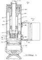
- Figure 1
- is a cross-sectional side view of a shock absorber incorporating the continuously variable damping capabilities in a completely damping fluid filled monotube configuration in accordance with the present invention,
- Figure 2
- is a schematic side view illustrating the servo valve shown in Figure 1 when the shock absorber is configured to provide a firm ride during rebound and a soft ride during compression of the shock absorber,
- Figure 3
- is a cross-sectional side view illustrating the servo valve shown in Figure 1 when the shock absorber is configured to provide a soft ride during rebound and a soft ride during compression of the shock absorber,
- Figure 4
- is a cross-sectional side view illustrating the servo valve shown in Figure 1 when the shock absorber is configured to provide a soft ride during rebound and a firm ride during compression of the shock absorber;
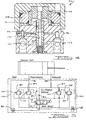
- Figure 5
- is a schematic view illustrating the hydraulic fluid circuit incorporated into the shock absorber shown in Figure 1, and
- Figure 6
- is a cross-sectional side view illustrating a typical poppet valve in accordance with the present invention.
- Referring now to the drawings in which like reference numerals designate like or corresponding parts throughout the several views, there is shown in Figure 1 a shock absorber incorporating the continuously variable damping adjustment system in accordance with the present invention which is designated generally by the reference numeral 10. Shock absorber 10 comprises a
piston 12, apiston rod 14, apressure tube 16, anouter tube 18, afloating piston 20 and a continuously variableservo valve assembly 22. Piston 12 is slidingly received withinpressure tube 16 and dividespressure tube 16 into an upper workingchamber 24 and alower working chamber 26. Piston 12 does not allow fluid flow betweenchambers - Piston
rod 14 is attached topiston 12 and extends out ofpressure tube 16 andouter tube 18 through arod guide 34. The outer end ofpiston rod 14 is adapted to be attached to either the sprung mass or the unsprung mass of the vehicle by means known well in the art.Outer tube 18surrounds pressure tube 16 and withpressure tube 16 defines an upperintermediate chamber 36 and a lower intermediate chamber 38.Outer tube 18 is adapted for attachment to the other of the sprung mass or the unsprung mass of the vehicle by methods known well in the art. A sealing ring orhousing 40 is sealingly disposed betweenouter tube 18 andpressure tube 16 to isolate upperintermediate chamber 36 from lower intermediate chamber 38. As can be seen in Figure 1,lower working chamber 26 extends out of the lower end ofpressure tube 16 to communicate with lower intermediate chamber 38 which is defined byhousing 40,outer tube 18 andfloating piston 20. Floatingpiston 20 is slidingly and sealingly disposed withinouter tube 18 to define the lower boundary of lower intermediate chamber 38 and agas chamber 42 located below floatingpiston 20. Floatingpiston 20 moves withinouter tube 18 to adjust for the rod volume during the stroking ofpiston 12 as is well know in the art.Outer tube 18 defines arebound outlet 54 in communication with upperintermediate chamber 36 and acompression outlet 56 in communication with lower intermediate chamber 38. - Referring now to Figures 1 and 2, continuously variable
servo valve assembly 22 is sealingly secured toouter tube 18. Continuously variableservo valve assembly 22 comprises asolenoid coil assembly 58, avalve body assembly 60 and aspool valve 62.Solenoid coil assembly 58 includes ahousing 64 within which is contained a set of windings 66 and abobbin 68. Avalve member 70 is disposed within the set of windings 66 and moves axially within windings 66 in response to electrical power being supplied to windings 66 as is well known in the art.Solenoid coil assembly 58 is attached tovalve body assembly 60.Spool valve 62 is disposed within abore 72 extending throughvalve body assembly 60. Aspring 74biases spool valve 62 towardssolenoid coil assembly 58. Thus,solenoid coil assembly 58 operates to movespool valve 62 axially withinbore 72 ofvalve body assembly 60.Spool valve 62 is normally in an upper position as shown in Figure 2 and is movable to a lower position as shown in Figure 4 when full power is being supplied tosolenoid coil assembly 58. By the use of pulse width modulation, the position ofspool valve 62 can be intermediate the positions shown in Figures 2 and 4 which is the position shown in Figure 3. - Referring now to Figures 2 and 5,
valve body assembly 60 comprises avalve body 76, acompression inlet 78, a compressionmain poppet 80, acompression co-poppet 82, acompression orifice 84, arebound inlet 88, a rebound main poppet 90, arebound co-poppet 92 and arebound orifice 94. A one-way check valve 96 is disposed betweencompression inlet 78 andspool valve 62.Check valve 96 permits flow fromspool valve 62 tocompression inlet 78 but prohibits fluid flow directly fromcompression inlet 78 tospool valve 62. Fluid flow is permitted fromcompression inlet 78 tospool valve 62 by way of compressionmain poppet 80,compression co-poppet 82 andcompression orifice 84.Check valve 96 also permits fluid flow from rebound main poppet 90 andrebound co-poppet 92. A oneway check valve 98 is disposed betweenrebound inlet 88 andspool valve 62.Check valve 98 permits flow fromspool valve 62 torebound inlet 88 but prohibits fluid flow directly fromrebound inlet 88 tospool valve 62. Fluid flow is permitted fromrebound inlet 88 tospool valve 62 by way of rebound main poppet 90,rebound co-poppet 92 andrebound orifice 94.Check valve 98 also permits fluid flow from compressionmain poppet 80 andcompression co-poppet 82. Valvebody assembly 60 is positioned such thatvalve body 76 sealingly engagesouter tube 18 withcompression inlet 78 sealinglyengaging compression outlet 56 and withrebound inlet 88 sealinglyengaging rebound outlet 54. Afluid passageway 100 extends between and fluidly connectsspool valve 62 andlower working chamber 26 throughcheck valve 96,compression inlet 78,compression outlet 56 and lower intermediate chamber 38. Afluid passage 102 extends between and fluidly connectsspool valve 62 and upper workingchamber 24 throughcheck valve 98, reboundinlet 88, reboundoutlet 54 and upperintermediate chamber 36. - Referring now to Figure 5, a fluid schematic diagram is shown. Fluid flow through
compression inlet 78 is directed to compressionmain poppet 80,compression co-poppet 82 andcompression orifice 84. Fluid flow through compressionmain poppet 80 andcompression co-poppet 82 is directed to upper workingchamber 24 throughpassage 102. Fluid flow throughcompression orifice 84 is directed throughspool valve 62 and then to upper workingchamber 24 throughpassage 102. Compressionmain poppet 80 is urged to a closed position by a biasingmember 104 and the fluid pressure present at a point betweencompression orifice 84 andspool valve 62. Fluid pressure fromcompression inlet 78 urges compressionmain poppet 80 towards an open position. In a similar manner,compression co-poppet 82 is urged into a closed position by a biasingmember 106 and the fluid pressure betweencompression orifice 84 andspool valve 62. Fluid pressure fromcompression inlet 78 also urgescompression co-poppet 82 toward an open position. Thus by controlling the amount of fluid allowed to pass fromcompression inlet 78 to upper workingchamber 24 throughcompression orifice 84, the fluid pressure urging compressionmain poppet 80 andcompression co-poppet 82 towards the open position can be controlled. Fluid flow throughrebound inlet 88 is directed to rebound main poppet 90, reboundco-poppet 92 and reboundorifice 94. Fluid flow through rebound main poppet 90 and rebound co-poppet 92 is directed to lower workingchamber 26 throughpassage 100. Fluid flow throughrebound orifice 94 is directed throughspool valve 62 and then to lower workingchamber 26 throughpassage 100. Rebound main poppet 90 is urged to a closed position by a biasingmember 108 and the fluid pressure present at a point betweenrebound orifice 94 andspool valve 62. Fluid pressure fromrebound inlet 88 urges rebound main poppet 90 towards an open position. In a similar manner, reboundco-poppet 92 is urged toward a closed position by a biasing member 110 and the fluid pressure present at a position betweenrebound orifice 94 andspool valve 62. Fluid pressure fromrebound inlet 88 also urges rebound co-poppet 92 towards an open position. Thus by controlling the amount of fluid allowed to pass fromrebound inlet 88 to lower workingchamber 26 throughrebound orifice 94, the fluid pressure urging rebound main poppet 90 and rebound co-poppet 92 towards the open position can be controlled. - During the operation of shock absorber 10, there is no damping force characteristic in either rebound or compression that is determined by
piston 12.Piston 12 is a solid piston without passages and valving between upper and lower workingchambers servo valve assembly 22 determines the damping force characteristics for shock absorber 10. The damping force characteristics for shock absorber 10 are controllable by continuously variableservo valve assembly 22 such that in any given complete stroke of shock absorber 10 (rebound to compression to rebound) depending on the amount of current given to energizesolenoid coil assembly 58. When little or no current is supplied tosolenoid coil assembly 58, continuously variableservo valve assembly 22 generates a firm rebound damping force with a soft compression damping force for shock absorber 10. When full current to solenoidcoil assembly 58 is supplied, continuously variableservo valve assembly 22 generates a soft rebound damping force with a firm compression damping force for shock absorber 10. - Another characteristic of continuously variable
servo valve assembly 22 is that when a continuously variable energy signal (through pulse width modulation) is provided tosolenoid coil assembly 58, a continuously variable sloping bleed and a continuously variable blowoff forpoppets - Figure 6 discloses schematically compression
main poppet 80. While Figure 6 is directed to compressionmain poppet 80, it is to be understood thatcompression co-poppet 82, rebound main poppet 90 and rebound co-poppet 92 operate in a similar manner tomain poppet 80. Compressionmain poppet 80 includes a valve member 112 disposed within abore 114 invalve body 76 ofvalve body assembly 60. Aspring 116 urges valve member 112 into a closed position as shown in Figure 6. Fluid flow fromcompression inlet 78 is directed to afluid inlet 118, through aninternal bore 120 in valve member 112, and then tocompression orifice 84. Fromcompression orifice 84, fluid flows back tointermediate chamber 36 through apassage 122. Ablowoff passage 124 extends frombore 114 topassage 122 to allow fluid flow when valve member 112 is moved to an open position. - The amount of fluid flow allowed through
compression orifice 84 and reboundorifice 94 will be determined by the position ofspool valve 62 as shown in Figures 2-4. In Figures 2-4,passage 122adjacent rebound inlet 88 returns fluid frompassage 122 ofrebound poppets 90 and 92 as well as fromrebound orifice 94.Passage 122 shownadjacent compression inlet 78 returns fluid frompassage 122 ofcompression poppets compression orifice 84. Figure 2 showsspool valve 62 positioned to fullyopen compression orifice 84 and fullyclose rebound orifice 94. Thus, a soft compression damping force and a firm rebound damping force are provided. Fluid is free to flow throughcompression orifice 84, through abore 126 extending throughspool valve 62, through bore 72 ofvalve body assembly 58, throughpassageway 102 and into upper workingchamber 24 to provide soft compression damping. Fluid is prohibited from flowing throughrebound orifice 94 thus providing firm compression damping. Figure 3 showsspool valve 62 positioned to open bothcompression orifice 84 and reboundorifice 94. Thus a soft compression damping force and a soft rebound damping force are provided. Fluid is free to flow through bothcompression orifice 84 into upper workingchamber 24 and throughrebound orifice 94 to lower workingchamber 26 as described above to provide soft compression and rebound damping. Figure 4 showsspool valve 62 positioned to fullyclose compression orifice 84 and fullyopen rebound orifice 94. Thus, a firm compression damping force and a soft rebound damping force are provided. Fluid is prohibited from flowing throughcompression orifice 84 to provide firm compression damping. Fluid is free to flow throughrebound orifice 94 into lower workingchamber 26 as described above to provide soft rebound damping. The amount of firm and/or soft damping provided will be determined by the position ofspool valve 62 which in turn is determined by the amount of current being supplied tosolenoid coil assembly 58. Preferably, the amount of current to solenoidcoil assembly 58 is controlled using pulse width modulation. - Referring now to Figure 6, the amount of flow through
spool valve 62 also contributes to the damping force blowoff level according to the following formula:
- In the above formula:
- Q
- = the blowoff level
- α
- = flow coefficient of damping fluid
- F
- = force
- P
- = pressure
- AS
- = diameter of
bore 114 - BH
- = diameter of valve member 112
- AO
- = diameter of
bore 120 - BV
- = area of
orifice - By varying the amount of flow through
orifice main poppet 80. The amount of force or fluid pressure required to displace valve member 112 and move it to its open position is determined by the area deferential of the upstream pressure face versus the downstream pressure face. By continuously varying the pressure on the downstream pressure face through the movement ofspool valve 62, the amount of force required to displace valve member 112 can be continuously varied thus resulting in a continuously variable damping force blowoff level. - In order to completely separate the operation of continuously variable
servo valve assembly 22 from rebound to compression, a complete separation of the fluid flow of the rebound to the fluid flow of the compression of the shock absorber 10 is required. A description of fluid flow during the rebound stroke and the compression stroke is detailed below. - Referring now to Figures 1 and 5, during the rebound stroke, because there is no valving in
piston 12, fluid is forced through apassage 130 formed inrod guide 34 and into upperintermediate chamber 36. The fluid enters upperintermediate chamber 36 which is concentric with workingchambers rebound outlet 54 and enters reboundinlet 88 of continuously variableservo valve assembly 22. After enteringrebound inlet 88, fluid flows to rebound main poppet 90, to reboundco-poppet 92 and to reboundorifice 94. As described above, the amount of flow throughrebound orifice 94 is controlled by the position ofspool valve 62 to control the damping characteristics from a soft ride to a firm ride. Fluid flowing through continuously variableservo valve assembly 22 is directed to lower intermediate chamber 38 and lower workingchamber 26. The rebound movement ofpiston 12 creates a low pressure within lower workingchamber 26 and intermediate chamber 38. Fluid leaving continuously variableservo valve assembly 22 throughcompression inlet 78 is allowed to enter lower workingchamber 26 to replenish the fluid on the bottom side ofpiston 12. Floatingpiston 20 moves axially withinouter tube 18 to compensate for the rod volume. - During the compression stroke, because there is no valving in
piston 12, fluid is forced from lower workingchamber 26 into lower intermediate chamber 38. The fluid enters lower intermediate chamber 38 which is concentric with workingchambers compression outlet 56 and enterscompression inlet 78 of continuously variableservo valve assembly 22. After enteringcompression inlet 78, fluid flows to compressionmain poppet 80,compression co-poppet 82 and tocompression orifice 84. As described above, the amount of flow throughcompression orifice 84 is controlled by the position ofspool valve 62 to control the damping characteristics from a soft ride to a firm ride. Fluid flowing through continuously variableservo valve assembly 22 is directed to upperintermediate chamber 36 and upper workingchamber 24. The compression movement ofpiston 12 creates a low pressure within upper workingchamber 24 and upperintermediate chamber 36. Fluid leaving continuously variableservo valve assembly 22 throughrebound inlet 88 is allowed to enter upperintermediate chamber 36 to replenish the fluid on the top side ofpiston 12 viapassage 130 inrod guide 34 which extends between upper workingchamber 24 and upperintermediate chamber 36. Floatingpiston 20 moves axially withinouter tube 18 to compensate for the rod volume. - The above construction for shock absorber 10 thus provides an infinitely variable solenoid actuated continuously variable shock absorber. Some, but not all of the advantages of this contraction are given below. First, shock absorber 10 provides a greater differentiation from soft to firm damping forces in compression due to the introduction of separate compression flow passages and check valves. Second, shock absorber 10 provides for a separately tunable rebound and compression valving. Third, shock absorber 10 provides soft compression damping forces and firm rebound damping forces during the same stroke. Conversely, firm compression damping forces and soft rebound damping forces during the same stroke are also available. In addition, shock absorber 10 does not require any piston valving system. Fifth, shock absorber 10 allows for continuously variable bleed and blowoff features. Sixth, continuously variable
servo valve assembly 22 differentiates between compression strokes and rebound strokes. - While the above detailed description describes the preferred embodiment of the present invention, it should be understood that the present invention is susceptible to modification, variation and alteration without deviating from the scope and fair meaning of the subjoined claims.
Claims (4)
- An adjustable shock absorber comprising :a pressure tube (16) defining a working chamber,a piston rod (14) extending through said pressure tube (16) and into said working chamber,a valveless piston (12) slidably disposed within said pressure tube (16) and connected to said piston rod (14), said piston (12) dividing said working chamber into an upper working chamber (24) and a lower working chamber (26),a valve assembly (22) separate from said piston (12) in communication with said upper and lower working chambers (24, 26), said valve assembly (22) including a hydraulic circuit with a first variable orifice (94) disposed between said upper working chamber (24) and said lower working chamber (26) for controlling fluid flow from said upper working chamber (24) to said lower working chamber (26) and a second variable orifice (84) disposed between said lower working chamber (26) and said upper working chamber (24) for controlling fluid flow from said lower working chamber (26) to said upper working chamber (24),characterizedin that the first variable orifice (94) is disposed in a first separate fluid flow path from said upper working chamber (24) to said lower working chamber (26) and that the second variable orifice (84) is disposed in a second separate fluid flow path from said lower working chamber (26) to said upper working chamber (24),in that one spool valve (62) is used to control fluid flow from the upper working chamber (24) through the first orifice (94) to the lower working chamber (26) and from the lower working chamber (26) through the second orifice (84) to said upper working chamber (24)and in that the first fluid path includes a first blowoff valve (90) and a second blowoff valve (92) in communication with the upper working chamber (24) and the lower working chamber (26) allowing fluid flow from the upper working chamber (24) to the lower working chamber (26) and the second fluid path includes as well a first blowoff valve (80) and a second blowoff valve (82) in communication with the lower working chamber (26) and the upper working chamber (24) allowing fluid flow from the lower working chamber (26) to the upper working chamber (24).
- The adjustable shock absorber according to claim 1 wherein said shock absorber (10) includes an outer tube (18) surrounding said pressure tube (16), said outer tube (18) defining an upper intermediate chamber (36) in communication with said upper working chamber (24) and a lower intermediate chamber (38) in communication with said lower working chamber (26).
- The adjustable shock absorber according to claim 2, wherein said shock absorber (10) includes a floating piston (20) slidably disposed within said outer tube (18).
- The adjustable shock absorber according to claim 2, wherein said shock absorber (10) includes a sealing ring disposed between said outer tube (18) and said pressure tube (16), said sealing ring prohibiting fluid communication between said upper intermediate chamber (36) and said lower intermediate chamber (38).
Applications Claiming Priority (2)
| Application Number | Priority Date | Filing Date | Title |
|---|---|---|---|
| US624120 | 2000-07-24 | ||
| US09/624,120 US6793048B1 (en) | 2000-07-24 | 2000-07-24 | Solenoid actuated continuously variable shock absorber |
Publications (3)
| Publication Number | Publication Date |
|---|---|
| EP1176333A2 EP1176333A2 (en) | 2002-01-30 |
| EP1176333A3 EP1176333A3 (en) | 2004-01-07 |
| EP1176333B1 true EP1176333B1 (en) | 2007-03-14 |
Family
ID=24500732
Family Applications (1)
| Application Number | Title | Priority Date | Filing Date |
|---|---|---|---|
| EP01117498A Expired - Lifetime EP1176333B1 (en) | 2000-07-24 | 2001-07-20 | Solenoid actuated continuously variable shock absorber |
Country Status (4)
| Country | Link |
|---|---|
| US (1) | US6793048B1 (en) |
| EP (1) | EP1176333B1 (en) |
| BR (1) | BR0103016A (en) |
| DE (1) | DE60127207T2 (en) |
Families Citing this family (4)
| Publication number | Priority date | Publication date | Assignee | Title |
|---|---|---|---|---|
| US7374028B2 (en) | 2003-07-08 | 2008-05-20 | Fox Factory, Inc. | Damper with pressure-sensitive compression damping |
| US7438164B2 (en) * | 2003-12-08 | 2008-10-21 | Tenneco Automotive Operating Company Inc. | Solenoid actuated continuously variable servo valve for adjusting damping in shock absorbers and struts |
| US20100137960A1 (en) * | 2008-12-03 | 2010-06-03 | Boston Scientific Neuromodulation Corporation | Implantable neurostimulators having reduced pocket stimulation |
| US11441633B2 (en) * | 2020-08-14 | 2022-09-13 | DRiV Automotive Inc. | Damper assembly including intake valve in fluid chamber |
Family Cites Families (21)
| Publication number | Priority date | Publication date | Assignee | Title |
|---|---|---|---|---|
| DE2024749C3 (en) * | 1970-05-21 | 1980-08-14 | Stabilus Gmbh, 5400 Koblenz | Device for continuously adjusting the inclination of the backrest of seats, in particular motor vehicle seats |
| US3722639A (en) * | 1971-03-03 | 1973-03-27 | Monroe Belgium Nv | Shock absorber including noise reducing means |
| US3757910A (en) | 1971-07-29 | 1973-09-11 | Monroe Auto Equipment Co | Shock absorber and compression valve assembly |
| US3807678A (en) * | 1972-09-19 | 1974-04-30 | Lord Corp | System for controlling the transmission of energy between spaced members |
| CA1058643A (en) | 1976-03-22 | 1979-07-17 | Dale A. Palmer | Shock absorber |
| US4828231A (en) * | 1986-01-30 | 1989-05-09 | Nhk Spring Co., Ltd. | Car suspension system |
| DE3610937A1 (en) * | 1986-04-02 | 1987-10-08 | Bosch Gmbh Robert | DEVICE FOR DAMPING MOTION PROCESSES |
| JPH0725251B2 (en) | 1987-01-16 | 1995-03-22 | 本田技研工業株式会社 | Related suspension device |
| US4854429A (en) | 1987-12-18 | 1989-08-08 | Casey Gary L | Variable rate shock absorber and system therefor |
| US4890858A (en) | 1988-02-16 | 1990-01-02 | Monroe Auto Equipment Company | Method and apparatus for controlling shock absorbers |
| DE4041619A1 (en) | 1990-12-22 | 1992-06-25 | Bosch Gmbh Robert | CYLINDER |
| DE4208886A1 (en) * | 1992-03-19 | 1993-09-23 | Fichtel & Sachs Ag | DAMPING FORCE CHANGEABLE VIBRATION DAMPER WITH EMERGENCY OPERATION ADJUSTMENT |
| US5328004A (en) * | 1992-08-21 | 1994-07-12 | General Motors Corporation | Bypass valve assembly for a hydraulic damper |
| SE511320C2 (en) * | 1993-04-23 | 1999-09-13 | Oehlins Racing Ab | Device for shock absorbers using hysteresis function to determine damping variation |
| US5586627A (en) | 1993-05-20 | 1996-12-24 | Tokico, Ltd. | Hydraulic shock absorber of damping force adjustable type |
| US5655633A (en) | 1994-05-20 | 1997-08-12 | Tokico Ltd. | Hydraulic damper of a damping force adjusting type |
| EP0715091B1 (en) * | 1994-12-03 | 2002-07-10 | ZF Sachs AG | Adjustable vibration damper |
| JPH08184344A (en) * | 1994-12-29 | 1996-07-16 | Tokico Ltd | Damping force regulation type hydraulic shock absorber |
| US5588510A (en) * | 1995-09-25 | 1996-12-31 | Husco International, Inc. | Variable damping force shock absorber |
| JPH09264364A (en) * | 1996-01-25 | 1997-10-07 | Tokico Ltd | Hydraulic buffer |
| JP3829264B2 (en) * | 1996-03-19 | 2006-10-04 | 株式会社日立製作所 | Damping force adjustable hydraulic shock absorber |
-
2000
- 2000-07-24 US US09/624,120 patent/US6793048B1/en not_active Expired - Fee Related
-
2001
- 2001-07-20 DE DE60127207T patent/DE60127207T2/en not_active Expired - Fee Related
- 2001-07-20 EP EP01117498A patent/EP1176333B1/en not_active Expired - Lifetime
- 2001-07-24 BR BR0103016-7A patent/BR0103016A/en active Search and Examination
Also Published As
| Publication number | Publication date |
|---|---|
| US6793048B1 (en) | 2004-09-21 |
| DE60127207D1 (en) | 2007-04-26 |
| EP1176333A2 (en) | 2002-01-30 |
| EP1176333A3 (en) | 2004-01-07 |
| DE60127207T2 (en) | 2007-12-13 |
| BR0103016A (en) | 2002-02-26 |
Similar Documents
| Publication | Publication Date | Title |
|---|---|---|
| US7438164B2 (en) | Solenoid actuated continuously variable servo valve for adjusting damping in shock absorbers and struts | |
| US5934422A (en) | Step motor actuated continuously variable shock absorber | |
| KR101326935B1 (en) | Damping force control type hydraulic damper | |
| US6464048B1 (en) | Solenoid actuated continuously variable shock absorber | |
| US5163538A (en) | Low level damping valve and method for a semi-active hydraulic damper | |
| US5503258A (en) | Hydraulic shock absorber | |
| KR100451289B1 (en) | Damping force adjustable hydraulic buffer | |
| EP0801249B1 (en) | Variable hydraulic shock absorber | |
| US8511444B2 (en) | Shock absorber having a continuously variable valve with base line valving | |
| US5328004A (en) | Bypass valve assembly for a hydraulic damper | |
| US5460355A (en) | Adjustable shock absorber | |
| US7770983B2 (en) | Damping force control valve and shock absorber using the same | |
| RU2469224C1 (en) | Automotive suspension adaptive damper | |
| US7604101B2 (en) | Damping force control valve and shock absorber using the same | |
| EP1975453A2 (en) | Damping force adjustable fluid pressure shock absorber | |
| JP2003166585A (en) | Attenuating force adjustable hydraulic damper | |
| WO1991016556A1 (en) | Adjustable shock absorber assembly | |
| JP2000193014A (en) | Damping force regulation type hydraulic buffer | |
| GB2223822A (en) | Hydraulic vibration damper with variable damping force | |
| EP1176333B1 (en) | Solenoid actuated continuously variable shock absorber | |
| JP4096153B2 (en) | Damping force adjustable hydraulic shock absorber | |
| US5647461A (en) | Adjustable piston valve damper | |
| JPH109327A (en) | Damping force regulating type hydraulic shock absorber | |
| RU2469225C1 (en) | Automotive suspension adaptive damper | |
| JP3650898B2 (en) | Damping force adjustable hydraulic shock absorber |
Legal Events
| Date | Code | Title | Description |
|---|---|---|---|
| PUAI | Public reference made under article 153(3) epc to a published international application that has entered the european phase |
Free format text: ORIGINAL CODE: 0009012 |
|
| AK | Designated contracting states |
Kind code of ref document: A2 Designated state(s): AT BE CH CY DE DK ES FI FR GB GR IE IT LI LU MC NL PT SE TR |
|
| AX | Request for extension of the european patent |
Free format text: AL;LT;LV;MK;RO;SI |
|
| PUAL | Search report despatched |
Free format text: ORIGINAL CODE: 0009013 |
|
| AK | Designated contracting states |
Kind code of ref document: A3 Designated state(s): AT BE CH CY DE DK ES FI FR GB GR IE IT LI LU MC NL PT SE TR |
|
| AX | Request for extension of the european patent |
Extension state: AL LT LV MK RO SI |
|
| RIN1 | Information on inventor provided before grant (corrected) |
Inventor name: KAZMIRSKI, KARL C. Inventor name: ZEBOLSKY, MICHAEL L. Inventor name: GROVES, GARY W. Inventor name: STEED, DAVID L. |
|
| 17P | Request for examination filed |
Effective date: 20040211 |
|
| 17Q | First examination report despatched |
Effective date: 20040402 |
|
| AKX | Designation fees paid |
Designated state(s): DE FR GB |
|
| GRAP | Despatch of communication of intention to grant a patent |
Free format text: ORIGINAL CODE: EPIDOSNIGR1 |
|
| GRAS | Grant fee paid |
Free format text: ORIGINAL CODE: EPIDOSNIGR3 |
|
| GRAA | (expected) grant |
Free format text: ORIGINAL CODE: 0009210 |
|
| AK | Designated contracting states |
Kind code of ref document: B1 Designated state(s): DE FR GB |
|
| REG | Reference to a national code |
Ref country code: GB Ref legal event code: FG4D |
|
| REF | Corresponds to: |
Ref document number: 60127207 Country of ref document: DE Date of ref document: 20070426 Kind code of ref document: P |
|
| ET | Fr: translation filed | ||
| PLBE | No opposition filed within time limit |
Free format text: ORIGINAL CODE: 0009261 |
|
| STAA | Information on the status of an ep patent application or granted ep patent |
Free format text: STATUS: NO OPPOSITION FILED WITHIN TIME LIMIT |
|
| 26N | No opposition filed |
Effective date: 20071217 |
|
| PGFP | Annual fee paid to national office [announced via postgrant information from national office to epo] |
Ref country code: FR Payment date: 20090716 Year of fee payment: 9 |
|
| PGFP | Annual fee paid to national office [announced via postgrant information from national office to epo] |
Ref country code: DE Payment date: 20090722 Year of fee payment: 9 Ref country code: GB Payment date: 20090720 Year of fee payment: 9 |
|
| GBPC | Gb: european patent ceased through non-payment of renewal fee |
Effective date: 20100720 |
|
| REG | Reference to a national code |
Ref country code: FR Ref legal event code: ST Effective date: 20110331 |
|
| PG25 | Lapsed in a contracting state [announced via postgrant information from national office to epo] |
Ref country code: DE Free format text: LAPSE BECAUSE OF NON-PAYMENT OF DUE FEES Effective date: 20110201 |
|
| REG | Reference to a national code |
Ref country code: DE Ref legal event code: R119 Ref document number: 60127207 Country of ref document: DE Effective date: 20110201 |
|
| PG25 | Lapsed in a contracting state [announced via postgrant information from national office to epo] |
Ref country code: FR Free format text: LAPSE BECAUSE OF NON-PAYMENT OF DUE FEES Effective date: 20100802 |
|
| PG25 | Lapsed in a contracting state [announced via postgrant information from national office to epo] |
Ref country code: GB Free format text: LAPSE BECAUSE OF NON-PAYMENT OF DUE FEES Effective date: 20100720 |