EP1175032A1 - Single-carrier/ds-cdma packet transmitting method, uplink packet transmitting method in multicarrier/ds-cdma mobile communication system, and structure of downlink channel in multicarrier/ds-cdma mobile communication system - Google Patents
Single-carrier/ds-cdma packet transmitting method, uplink packet transmitting method in multicarrier/ds-cdma mobile communication system, and structure of downlink channel in multicarrier/ds-cdma mobile communication system Download PDFInfo
- Publication number
- EP1175032A1 EP1175032A1 EP01902743A EP01902743A EP1175032A1 EP 1175032 A1 EP1175032 A1 EP 1175032A1 EP 01902743 A EP01902743 A EP 01902743A EP 01902743 A EP01902743 A EP 01902743A EP 1175032 A1 EP1175032 A1 EP 1175032A1
- Authority
- EP
- European Patent Office
- Prior art keywords
- packet transmission
- reservation demand
- spreading codes
- packet
- base station
- Prior art date
- Legal status (The legal status is an assumption and is not a legal conclusion. Google has not performed a legal analysis and makes no representation as to the accuracy of the status listed.)
- Withdrawn
Links
Images






















Classifications
-
- H—ELECTRICITY
- H04—ELECTRIC COMMUNICATION TECHNIQUE
- H04J—MULTIPLEX COMMUNICATION
- H04J13/00—Code division multiplex systems
-
- H—ELECTRICITY
- H04—ELECTRIC COMMUNICATION TECHNIQUE
- H04W—WIRELESS COMMUNICATION NETWORKS
- H04W72/00—Local resource management
- H04W72/12—Wireless traffic scheduling
- H04W72/1263—Mapping of traffic onto schedule, e.g. scheduled allocation or multiplexing of flows
- H04W72/1268—Mapping of traffic onto schedule, e.g. scheduled allocation or multiplexing of flows of uplink data flows
-
- H—ELECTRICITY
- H04—ELECTRIC COMMUNICATION TECHNIQUE
- H04L—TRANSMISSION OF DIGITAL INFORMATION, e.g. TELEGRAPHIC COMMUNICATION
- H04L5/00—Arrangements affording multiple use of the transmission path
- H04L5/0001—Arrangements for dividing the transmission path
- H04L5/0014—Three-dimensional division
- H04L5/0016—Time-frequency-code
- H04L5/0019—Time-frequency-code in which one code is applied, as a temporal sequence, to all frequencies
-
- H—ELECTRICITY
- H04—ELECTRIC COMMUNICATION TECHNIQUE
- H04L—TRANSMISSION OF DIGITAL INFORMATION, e.g. TELEGRAPHIC COMMUNICATION
- H04L5/00—Arrangements affording multiple use of the transmission path
- H04L5/003—Arrangements for allocating sub-channels of the transmission path
- H04L5/0053—Allocation of signalling, i.e. of overhead other than pilot signals
-
- H—ELECTRICITY
- H04—ELECTRIC COMMUNICATION TECHNIQUE
- H04L—TRANSMISSION OF DIGITAL INFORMATION, e.g. TELEGRAPHIC COMMUNICATION
- H04L5/00—Arrangements affording multiple use of the transmission path
- H04L5/003—Arrangements for allocating sub-channels of the transmission path
- H04L5/0058—Allocation criteria
- H04L5/0064—Rate requirement of the data, e.g. scalable bandwidth, data priority
-
- H—ELECTRICITY
- H04—ELECTRIC COMMUNICATION TECHNIQUE
- H04L—TRANSMISSION OF DIGITAL INFORMATION, e.g. TELEGRAPHIC COMMUNICATION
- H04L5/00—Arrangements affording multiple use of the transmission path
- H04L5/003—Arrangements for allocating sub-channels of the transmission path
- H04L5/0078—Timing of allocation
- H04L5/0087—Timing of allocation when data requirements change
-
- H—ELECTRICITY
- H04—ELECTRIC COMMUNICATION TECHNIQUE
- H04L—TRANSMISSION OF DIGITAL INFORMATION, e.g. TELEGRAPHIC COMMUNICATION
- H04L5/00—Arrangements affording multiple use of the transmission path
- H04L5/0091—Signalling for the administration of the divided path, e.g. signalling of configuration information
- H04L5/0092—Indication of how the channel is divided
-
- H—ELECTRICITY
- H04—ELECTRIC COMMUNICATION TECHNIQUE
- H04L—TRANSMISSION OF DIGITAL INFORMATION, e.g. TELEGRAPHIC COMMUNICATION
- H04L5/00—Arrangements affording multiple use of the transmission path
- H04L5/02—Channels characterised by the type of signal
- H04L5/06—Channels characterised by the type of signal the signals being represented by different frequencies
-
- H—ELECTRICITY
- H04—ELECTRIC COMMUNICATION TECHNIQUE
- H04W—WIRELESS COMMUNICATION NETWORKS
- H04W72/00—Local resource management
- H04W72/04—Wireless resource allocation
- H04W72/044—Wireless resource allocation based on the type of the allocated resource
- H04W72/0446—Resources in time domain, e.g. slots or frames
-
- H—ELECTRICITY
- H04—ELECTRIC COMMUNICATION TECHNIQUE
- H04W—WIRELESS COMMUNICATION NETWORKS
- H04W72/00—Local resource management
- H04W72/04—Wireless resource allocation
- H04W72/044—Wireless resource allocation based on the type of the allocated resource
- H04W72/0453—Resources in frequency domain, e.g. a carrier in FDMA
-
- H—ELECTRICITY
- H04—ELECTRIC COMMUNICATION TECHNIQUE
- H04W—WIRELESS COMMUNICATION NETWORKS
- H04W72/00—Local resource management
- H04W72/50—Allocation or scheduling criteria for wireless resources
- H04W72/52—Allocation or scheduling criteria for wireless resources based on load
-
- H—ELECTRICITY
- H04—ELECTRIC COMMUNICATION TECHNIQUE
- H04B—TRANSMISSION
- H04B1/00—Details of transmission systems, not covered by a single one of groups H04B3/00 - H04B13/00; Details of transmission systems not characterised by the medium used for transmission
- H04B1/69—Spread spectrum techniques
- H04B1/707—Spread spectrum techniques using direct sequence modulation
-
- H—ELECTRICITY
- H04—ELECTRIC COMMUNICATION TECHNIQUE
- H04L—TRANSMISSION OF DIGITAL INFORMATION, e.g. TELEGRAPHIC COMMUNICATION
- H04L5/00—Arrangements affording multiple use of the transmission path
- H04L5/003—Arrangements for allocating sub-channels of the transmission path
- H04L5/0048—Allocation of pilot signals, i.e. of signals known to the receiver
-
- H—ELECTRICITY
- H04—ELECTRIC COMMUNICATION TECHNIQUE
- H04W—WIRELESS COMMUNICATION NETWORKS
- H04W72/00—Local resource management
- H04W72/50—Allocation or scheduling criteria for wireless resources
- H04W72/56—Allocation or scheduling criteria for wireless resources based on priority criteria
- H04W72/563—Allocation or scheduling criteria for wireless resources based on priority criteria of the wireless resources
Definitions
- the present invention relates to DS-CDMA (Direct Sequence-Code Divisional Multiple Access) mobile communications, and particularly relates to single carrier/DS-CDMA mobile communications and multi-carrier/DS-CDMA mobile communications.
- DS-CDMA Direct Sequence-Code Divisional Multiple Access
- the multi-carrier/DS-CDMA divides a radio-transmission bandwidth, and performs parallel transmission of a CDMA signal by two or more subcarriers.
- the multi-carrier/DS-CDMA mobile communication system has been attracting attention as a mobile communication system that is capable of high-speed data transmission.
- This multi-carrier/DS-CDMA mobile communication system has a problem in that no scheme has yet been proposed about a channel structure that takes into account the above-described asymmetry in the amount of data transmission between the uplink and the downlink in high-speed data communications directed to multimedia or the like.
- the first object of the present invention relative to the single carrier/DS-CDMA packet transmission method and transmission system is to provide multiplexing of a reservation demand packet and a data packet efficiently, to improve transmission efficiency, and further to realize a flexible bandwidth control of a channel wherein the reservation demand packet and the data packet occupy according to changes in traffic amount.
- the present invention relative to an uplink packet transmission method in a multi-carrier/DS-CDMA mobile communication system that has n subcarriers (n being a natural number two or larger) is structured such that frames that are segments for every fixed time are provided to each communication channel of the above-mentioned subcarriers, the frame is divided into time slots with F pieces (F 5 being a natural number, two or larger), and a mobile station transmits a packet to be transmitted to a base station by spreading by a spreading code in synchronous with the timing of the above-mentioned time slot.
- the uplink packet transmission method for the multi-carrier/DS-CDMA mobile communication system which has n subcarriers is structured such that:
- the third object of the present invention is to provide a downlink channel structure that is capable of efficiently transmitting control information to each user in a situation where information transmission volumes are asymmetrical between an uplink and a downlink in a multi-carrier/DS-CDMA mobile communication system.
- the present invention relative to the structure of the downlink channel in the multi-carrier/DS-CDMA mobile communication system that transmits spreading codes obtained by expanding bandwidth of information symbols by a spreading code sequence using two or more subcarriers that have a predetermined frequency interval, is structured such that two or more communication channels assigned to each of two or more subcarriers are divided for every predetermined time frame, multiplexed and assigned to each subcarrier, the two or more communication channels being used by a common control channel for two or more users, and a communication channel peculiar to each user.
- the downlink of the present invention can be structured such that information for controlling transmission of each user's uplink is included in the above-mentioned common-control channel.
- the information for controlling transmission of each user's uplink can include a transmission power control command to control the transmission power of each user (mobile station), a control command used to control a call origination, and a control command to control, for example, to control frequency, code (including a spreading factor), and time to be used by each user.
- each downlink channel of the present invention can include information relative to a response to transmission of each user's uplink in the above-mentioned common-control channel.
- the information relative to the response to transmission of each user's uplink can include, for example, a reply signal ACK (Acknowledgement) and NACK (Non-acknowledgement) to an uplink communication.
- the present invention can include the common broadcast information to each user in the above-mentioned common-control channel in the structure of each downlink channel mentioned above.
- the broadcast information to each user mentioned above can include time, cell (base station) information, traffic information about the cell to which the mobile station is connected, road traffic information, and broadcast information such as about television and the like.
- the present invention can include a pilot symbol used for demodulating the received signal at each user in the above-mentioned common-control channel in the structure of each above-mentioned downlink channel.
- the present invention allows an assignment of a common-control channel to one or a plurality of code channels of part or all of the plurality of subcarriers in the structure of each above-mentioned downlink channel.
- the present invention allows the common-control channel in each subcarrier in the structure of each above-mentioned downlink channel to accommodate different kinds of information.
- the present invention allows information that is included in the common-control channel assigned to each subcarrier to be time-multiplexed into part of each time frame in the structure of each above-mentioned downlink channel.
- time-multiplexing may be carried out with respect to the same timing portion of each time frame of each-subcarrier, or may be carried out with respect to different timing portions of each time frame of each subcarrier as claimed in claim 10.
- Fig. 1 is a drawing showing an example of a channel structure of the first embodiment.
- Fig. 2 is a drawing showing another example of the channel structure.
- Fig. 3 is a drawing showing an example of controlling reservation demand packet transmission admission probability.
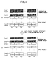
- Fig. 4 is a drawing showing an example of assignment control of the number of spreading codes.
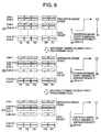
- Fig. 6 is a drawing showing an example of the reservation demand packet transmission admission probability control and the assignment control of available number of the spreading codes for a reservation demand packet of the first embodiment.
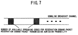
- Fig. 7 is a drawing showing a channel structure of a broadcast channel in a downlink.
- Fig. 8 is a drawing showing an example in which a reservation demand packet and a data packet are bandwidth-spread using a short repetition period spreading code.
- Fig. 9 is a drawing showing an example in which the reservation demand packet is spread by the short repetition period spreading code, and the data packet is spread by a long repetition period spreading code.
- Fig. 10 is a drawing showing the first implementation of the first embodiment.
- Fig. 11 is a drawing showing the second implementation
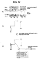
- Fig. 12 is a drawing showing the third implementation
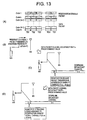
- Fig. 13 is a drawing showing the fourth implementation
- Fig. 14 is a drawing showing the fifth implementation
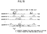
- Fig. 15 is a drawing showing an example of the channel structure of the second embodiment between a mobile station and a base station in the multi-carrier/DS-CDMA method.
- Fig. 16 is a drawing (No. 1) showing an example of an exchange of control performed between the mobile station and the base station when transmitting a packet from the mobile station to the base station in the second embodiment.
- Fig. 17 is a drawing (No. 2) showing an example of an exchange of control performed between the mobile station and the base station when transmitting a packet from the mobile station to the base station.
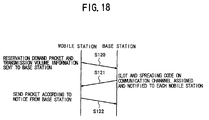
- Fig. 18 is a drawing (No. 3) showing an example of an exchange of control performed between the mobile station and the base station when transmitting a packet from the mobile station to the base station.
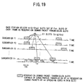
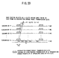
- Fig. 19 is a drawing (No. 1) showing assignment of a reservation demand packet transmission slot in the second embodiment.
- Fig. 20 is a drawing (No. 2) showing assignment of the reservation demand packet transmission slot.
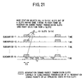
- Fig. 21 is a drawing (No. 3) showing assignment of the reservation demand packet transmission slot.
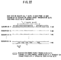
- Fig. 22 is a drawing (No. 4) showing assignment of the reservation demand packet transmission slot.
- Fig. 23 is a drawing (No. 5) showing assignment of the reservation demand packet transmission slot.
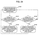
- Fig. 24 is a drawing showing changes of the number of time slots for the reservation demand packet transmission.
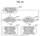
- Fig. 25 is a drawing showing changes of the number of spreading codes for the reservation demand packet transmission.
- Fig. 26 is a drawing showing changes of the number of time slots, and the number of spreading codes for the reservation demand packet transmission.
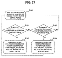
- Fig. 27 is a drawing showing a transmission limit of the reservation demand packet.
- Fig. 28 is a drawing (No. 1) showing assignment of a random access packet transmission slot in the second embodiment.
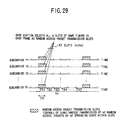
- Fig. 29 is a drawing (No. 2) showing assignment of the random access packet transmission slot.
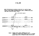
- Fig. 30 is a drawing (No. 3) showing assignment of the random access packet transmission slot.
- Fig. 31 is a drawing (No. 4) showing assignment of the random access packet transmission slot.
- Fig. 32 is a drawing (No. 5) showing assignment of the random access packet transmission slot.
- Fig. 33 is a drawing showing changes of the number of time slots for the random access packet transmission.
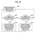
- Fig. 34 is a drawing showing changes of 5 the number of spreading codes for the random access packet transmission.
- Fig. 35 is a drawing showing changes of the number of time slots, and the number of spreading codes for the random access packet transmission.
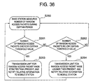
- Fig. 36 is a drawing showing a transmission limit of the random access packet.
- Fig. 37 is a drawing (No. 1) showing assignment of spreading codes according to a transmission volume.
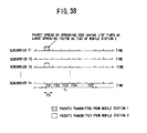
- Fig. 38 is a drawing (No. 2) showing assignment of the spreading code according to the transmission volume.
- Fig. 39 is a drawing showing assignment of the number of time slots according to the transmission volume.
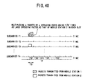
- Fig. 40 is a drawing (No. 3) showing assignment of the spreading code according to the transmission volume.
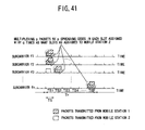
- Fig. 41 is a drawing (No. 1) showing assignment of the time slot and a spreading code according to the transmission volume in the second embodiment.
- Fig. 42 is a drawing (No. 2) showing assignment of the time slot and a spreading code according to the transmission volume.
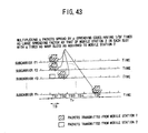
- Fig. 43 is a drawing (No. 3) showing assignment of the time slot and a spreading code according to the transmission volume.
- Fig. 44 is a block diagram showing a fundamental structure of a base station in the third embodiment of the present invention.
- Fig. 45 is a block diagram showing the first structure example of a common-control channel generation unit in the third embodiment.
- Fig. 46 is a block diagram showing the second structure example of the common-control 0 channel generation unit.
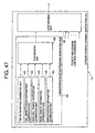
- Fig. 47 is a block diagram showing the third structure example of the common-control channel generation unit.
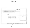
- Fig. 48 is block diagram showing the fourth structure example of the common-control channel generation unit.
- Fig. 49 is a drawing showing the first example a downlink channel structure in the third embodiment.
- Fig. 50 is a drawing showing the second example of the downlink channel structure.
- Fig. 51 is a drawing showing the third example of the downlink channel structure.
- Fig. 52 is a drawing showing the fourth 5 example of the downlink channel structure.
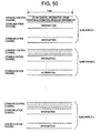
- Fig. 53 is a drawing showing the fifth example of the downlink channel structure.
- the first embodiment of the present invention is an embodiment concerning a single carrier/DS-CDMA packet transmission method.
- Fig. 1 is an example of a channel structure of the first embodiment.
- the horizontal axis and the vertical axis of each channel show time and power, respectively.
- Information signal is bandwidth-spread by a high-speed spreading code sequence, and the information signal whose bandwidth is expanded is transmitted by spreading codes Code1 through CodeN and time slots TS1 through TSM. At this occasion, a certain specific time slot is assigned to the reservation demand packet transmission.
- the time slot TS1 is assigned to the reservation demand packet transmission and the other time slots TS2 through TSM are assigned to data packets.
- the assignment to the reservation demand packet may be performed to part or all of the spreading codes.
- Fig. 2 is another example of the channel structure of the first embodiment.
- the horizontal axis and the vertical axis of each channel show time and power, respectively.
- Bandwidth expansion of the information symbol is carried out by the high-speed spreading code sequence, and the information signal of which bandwidth is expanded is transmitted by the spreading codes Codel through CodeN and the time slots TS1 through TSM.
- a certain specific spreading code is assigned to the reservation demand packet transmission.
- the spreading codes Code1 through CodeN are assigned to the reservation demand packet transmission, and 5 the other spreading codes Code (k+1) through CodeN are assigned to the data packets.
- Fig. 3 is an example of transmission admission probability control for reservation demand packet.
- Fig. 4 is an example of assignment control of the number of spreading codes available to a reservation demand packet.
- the horizontal axis and the vertical axis of each channel show time and power, respectively.
- Bandwidth expansion of the information symbol is carried out by the high-speed spreading code sequence, and the spread code of which bandwidth is expanded is transmitted by the spreading codes Code1 through CodeN and the time slots TS1 through TSM.
- a certain specific spreading code is assigned to reservation demand packet transmission.
- the spreading codes Code1 through Codek are assigned to the reservation demand packet transmission.
- transmission efficiency can be raised by decreasing the number of the spreading codes currently assigned to the reservation demand packet, and increasing the number of the spreading codes assigned to the data packets.
- m pieces of the spreading codes (m ⁇ k) are reassigned to the data-packet transmission from those assigned to the reservation demand packet transmission.
- transmission efficiency can be raised by using the spreading codes Code (k-m+1) through Codek previously assigned to the reservation demand packet will now be used by the data packet.
- Fig. 5 is an example of assignment control of the number of the spreading codes available to the reservation demand packet transmission and the transmission probability of the reservation demand packet.
- the horizontal axis and the vertical axis of each channel show time and power, respectively.
- Bandwidth expansion of the information symbol is carried out by the high-speed spreading code sequence, and the spread code of which bandwidth is expanded is transmitted by the spreading codes Code1 through CodeN and the time slots TS1 through TSM.
- a certain specific spreading code is assigned to reservation demand packet transmission.
- the transmission admission probability q (0 ⁇ q ⁇ p) for the reservation demand packet is lowered first as shown in Fig. 5 (B).
- the transmission efficiency is raised by decreasing the number of the spreading codes currently assigned to the reservation demand packet, and increasing the number of the spreading codes assigned to a data packet, as shown in Fig. 5 (C).
- m pieces of the spreading codes (m ⁇ k) are reassigned to the data packet from the reservation demand packet.
- transmission efficiency can be raised by the data packet using the spreading codes Code (k-m +1) through Codek currently assigned to the reservation demand packet.
- Fig. 6 is an example of assignment control of the number of spreading codes available to the reservation demand packets and the reservation demand packet transmitting probability.
- the horizontal axis and the vertical axis of each channel show time and power, respectively.
- Bandwidth expansion of the information symbol is carried out by the high-speed spreading code sequence, and the information signal of which bandwidth is expanded is transmitted by the spreading codes Code1 through CodeN and the time slots TS1 through TSM.
- a certain specific spreading code is assigned to the reservation demand packet transmission.
- a channel occupancy rate of a data packet exceeds a predetermined value at this time, the number of the spreading codes currently assigned to the reservation demand packet is decreased, and the number of the spreading codes assigned to the data packet is increased.
- m pieces of the spreading codes are reassigned to the data packet from the reservation demand packet.
- the transmission admission probability q (0 ⁇ q ⁇ p) for the reservation demand packet is lowered as shown in Fig. 6 (C).
- Fig. 7 is the example of a structure of the downlink broadcast channel in the first embodiment.
- Fig. 8 shows an example of a period of the spreading code for the bandwidth expansion of the reservation demand packet and the data packet in the first embodiment.
- both the reservation demand packet and the data packet are bandwidth-spread by a short repetition period spreading code.
- Fig. 10 (A) shows a channel structure
- Fig. 10 (B) shows a normal situation
- Fig. 10 (C) is a drawing that shows a control of the transmission admission probability for the reservation demand packet when a channel occupancy rate of a data packet exceeds a predetermined value.
- Fig. 11 (A) shows a channel structure
- Fig. 11 (B) shows a normal situation
- Fig. 11 (C) is a drawing showing a reservation demand packet transmission admission probability control when the channel occupancy rate of the data packet exceeds a predetermined value.
- Fig. 11 shows a control of the reservation demand packet transmission admission probability corresponding to Fig. 3, using the packet multiplexing method shown in Fig. 2 and the downlink broadcast channel structure shown in Fig. 7.
- Fig. 12 (A) shows a channel structure
- Fig. 12 (B) shows a normal situation
- Fig. 12 (C) is a drawing showing control of the number of assigning spreading codes for the reservation demand packet transmission when a channel occupancy rate of the data packet exceeds a predetermined value.
- Fig. 12 shows assignment control of the number of the spreading codes available to the reservation demand packet corresponding to Fig. 4, using the packet multiplexing method shown in Fig. 2 and the downlink broadcast channel structure in Fig. 7.
- the base station transmits a command that performs control to reduce the number of spreading codes assigned for the reservation demand packet transmission to k-m (0 ⁇ m ⁇ k) by inserting the command into the downlink broadcast channel by the time-multiplexing.
- the base station Based on the information about the assignment demand and the transmission volume from the mobile station, the base station assigns a time slot and a spreading code on a communication channel according to the transmission volume of the mobile station, and notifies the result to the mobile station (S121).
- the mobile station transmits packets based on the notified result (S122).
- a time slot TS1 of a subcarrier f1, a time slot TS1 of a subcarrier f2, and a time-slot TS2 of a subcarrier f3 and the like are assigned as the reservation demand packet transmission time slots.
- a channel structure wherein part of the time slot TS1 is set up as the reservation demand packet transmission time slot (k1 ⁇ n) in all subcarriers. Selection of the k1 pieces of the time slots may be dispersedly from any subcarriers, or may be continuously.
- the number of subcarriers that set up reservation demand packet transmission time slots may be two or larger.
- a reservation demand may not be responded. Then, according to the number of the reservation demand packets the number of time slots, the number of spreading codes, and the like for the reservation demand packet transmission are changed.
- the base station measures the number of the reservation demand packets transmitted from the mobile station during the predetermined period (S130).
- the measuring result indicates that the number of the reservation demand packets is larger than a certain threshold (YES in S131)
- the number of the reservation demand packet transmission slots is increased, and the position of the time slot is notified to the mobile station (S133).
- the measuring result indicates that the number of the reservation demand packets is below the threshold (YES in S132)
- the number of the reservation demand packet transmission slots is decreased, and the position of the time slot is notified to the mobile station (S134).
- the mobile station transmits a reservation demand packet according to the position of the reservation demand packet transmission time slot notified from the base station.
- the base station measures the number of the reservation demand packets transmitted from the mobile station during the predetermined period (S140).
- the measuring result indicates that the number of the reservation demand packets is below the threshold (YES in S142)
- the number m1 of spreading codes for spreading the reservation demand packet is decreased, and its parameter is notified to the mobile station (S144).
- the spreading code for spreading the reservation demand packet is not changed.
- the base station measures the number of the reservation demand packets transmitted from the mobile station during the predetermined period (S150).
- Fig. 27 is a drawing showing an example of control performed in the base station in the case of the base station limiting transmission of a reservation demand packet from the mobile station (for example, transmission of a reservation demand packet being restricted temporarily) since a possibility of inaccurate transmission of a reservation demand packet increases when the number of the reservation demand packets increases, and the mobile station transmitting a reservation demand packet according to the limit.
- the base station measures the number of the reservation demand packets transmitted from the mobile station during a predetermined period (S160).
- the transmission limit of the reservation demand packet is made looser than the current condition, and the fact is notified to the mobile station (S164).
- the time slot TS1 of the subcarrier f1, the time slot TS1 of the subcarrier f2, and the time-slot TS2 of the subcarrier f3 and the like are assigned as the random access packet transmission time slots.
- Fig. 30 shows an example of the channel structure where the time slots of the time slot TS1 generated for every frame of some subcarriers are set up as the random access packet transmission time slots (k2 ⁇ n). Selecting the k2 pieces of the time slots may be from dispersed subcarriers, or from subcarriers adjacent each other.
- Fig. 32 shows an example of the channel structure where part of time slots of one subcarrier are set up as the random access packet transmission time slots (k2 ⁇ F).
- the time slot TS1, the time slot TS2, and the time-slot TS4 and the like of the subcarrier f1 are assigned as the random access packet transmission time slots.
- Selecting the k2 pieces of time slots may be from dispersed time slots, or time slots adjacent each other.
- the base station measures the number of random access packets transmitted from the mobile stations during the predetermined period (S230).
- the measuring result indicates that the number of random access packets is below the threshold (YES in S232)
- the number of the random access packet transmission slots is decreased, and the position of the time slot is notified to the mobile stations (S234).
- the mobile station transmits a random access packet according to the position of the random access packet transmission time slot notified from the base station.
- the base station measures the number of the random access packets transmitted from the mobile stations during a predetermined period (S240).
- the measuring result indicates that the number of random access packets is larger than a certain threshold (YES in S241), the number of spreading codes m2 for spreading a random access packet is increased, and its parameter is notified to the mobile station (S243).
- the measuring result indicates that the number of the random access packets is below the threshold (YES in S242)
- the number of the spreading codes m2 for spreading the random access packet is decreased, and its specification is notified to the mobile station (S244).
- the mobile station chooses one from the spreading codes notified from the base station for the random access packet transmission, and spreads and transmits the random access packet.
- the measuring result indicates that the number of the random access packets is larger than the threshold (YES in S251), "the number of the spreading codes for spreading the random access packet m2 is increased” or “the number of the random access packet transmission slots k2 is increased” or “both are increased”, and the fact thereof is notified to the mobile station (S253).
- the measuring result indicates that the number of the random access packets is below the threshold (YES in S252), "the number of the spreading codes for spreading the random access packet m2 is decreased” or “the number of the random access packet transmission slots k2 is decreased” or “both are decreased”, and the fact thereof is notified to the mobile station (S254).
- the mobile station chooses one from the positions of the random access packet transmission time slots and the spreading codes for the random access packet transmission, which are notified from the base station, and spreads and transmits the random access packet.
- the base station measures the number of the random access packets transmitted from the mobile station during the predetermined period (S260).
- the transmission limit of a random access packet is made looser than the current condition, and the fact thereof is notified to the mobile station (S264).
- the transmission limit is not changed, when the number of the random access packets is not larger than the threshold (NO in S261) and the number of the random access packets is not below the threshold (NO in S262).
- a mobile station changes a transmission speed according to the magnitude of the transmission volume of packets that the mobile station is to transmit.
- a mode of the change of the transmission speed according to the transmission volume is shown.
- a mobile station 1 uses p pieces of spreading codes for packet multiplexing and transmits the packets at a transmission speed p times as fast in comparison with a transmission speed of a mobile station 2.
- Fig. 38 is a drawing showing an example which realizes a variable transmission speed by a base station assigning a mobile station a spreading code, spreading factor of which is changed according to the transmission volume of the mobile station within one time slot TS of a communication channel.
- Fig. 38 shows how the transmission speed of the mobile station 1 is made SF times as fast as compared with the mobile station 2 (a chip rate being the same) by using a spreading code, spreading factor of which is 1/SF of the spreading code for the mobile station 2, for spreading packets of the mobile station 1.
- Fig. 40, Fig. 41, Fig. 42, and Fig. 43 describe an embodiment wherein how the base station performs an assignment by changing at least two of the number of spreading codes p, a spreading factor of the spreading code, the number of time slots q, according to the transmission volume of the mobile station.
- the transmission speed of the mobile station 1 is set at pxSF times in comparison with the mobile station 2, by assigning the mobile station 1 p pieces of spreading codes that have a 1/SF spreading factor of the spreading factor of the spreading code of the mobile station 2, in addition to as described in Fig. 38
- the transmission speed of the mobile station 1 is further set at pxq times of the mobile station 2 by assigning p spreading codes to each time slot of the mobile station 1, in addition to as described in Fig. 39.
- Fig. 43 shows an example wherein the transmission speed of the mobile station 1 is set at pxqxSF times of the mobile station 2 by assigning q times as many time slot as the mobile station 2 to the mobile station 1, and further assigning p pieces of spreading codes that have a 1/SF spreading factor of the spreading factor of the spreading code of the mobile station 2 in each time slot of the mobile station 1.
- the third embodiment is an embodiment relative to downlinks in a multi-carrier/DS-CDMA mobile communication system.
- a base station transmitting information to each user with a downlink channel structure of the third embodiment of the present invention is configured as shown in Fig. 44, for example.
- the multi-carrier/DS-CDMA method is used for this base station as an access method.
- this base station includes a common-control channel generation unit 11, user channel generation units 12 (#1) through 12 (#m), a multiplexing unit 13, a multi-carrier modulation unit 14, and a transmitting unit 15.
- the common-control channel generation unit 11 carries out bandwidth expansion of a control information symbol of each user according to a specific spreading code sequence, and generates a spreading code corresponding to the control information symbol.
- Each of the user channel generation units 12 (#1) through 12 (#m) carries out the bandwidth expansion of the information symbol which is to be transmitted to each user according to the spreading code sequence corresponding to each user, and generates the spreading code corresponding to the information symbol.
- the multiplexing unit 13 synthesizes the spread codes corresponding to the information symbol from each user channel generation units 12 (#1)-12 (#m), then the synthesized signal and the spread codes corresponding to the control information symbol from the above-mentioned common-control channel generation unit 11 are multiplexed according to a predetermined algorithm.
- the algorithm of this multiplexing can be set up arbitrarily. For example, information can be multiplexed using time multiplexing wherein information is inserted periodically in every fixed period, frequency multiplexing wherein information is inserted into a certain specific subcarrier, or code multiplexing wherein multiplexing is performed by a certain specific code, or any combination thereof.
- the multi-carrier modulation unit 14 modulates so that the multiplexed signal from the multiplexing unit 13 is distributed over a plurality (n pieces) of subcarrier (multi-carrier) components (the inverse discrete Fourier transform: IDFT). Then, the signal containing the two or more subcarrier components obtained in this multi-carrier modulation unit 14 is transmitted to the transmitting unit 15 one by one, and the above-mentioned signal is transmitted from this transmitting unit 15 to each user (mobile station).
- IDFT inverse discrete Fourier transform
- a frequency interval of the subcarriers used in the above-mentioned multi-carrier modulation unit 14 is set up at p times (p being a positive real number) of an updating frequency (chip rate) of each spreading code sequence used in the common-control channel generation unit 11 and each of the user channel generation units 12 (#1) through 12 (#m).
- the above-mentioned common-control channel generation unit 11 is structured as shown in Fig. 45.
- the common-control channel generation unit 11 includes an uplink transmission-control information generation unit 20 and a synthesizing unit 60.
- the uplink transmission-control information generation unit 20 generates information for controlling a transmission from each user (mobile station), and includes a transmission power control information generation unit 21, a first transmission-control information generation unit 22, a second transmission-control information generation unit 23, a channel allocation information generation unit 24, and a synthesizing unit 25.
- the transmission power control command from the above-mentioned transmission power control information generation unit 21 varies according to a state of a communication transmission channel between each user (mobile station), and serves as control information peculiar to each user.
- each control information from the first transmission-control information generation unit 22 and the second transmission-control information generation unit 23 and information about the channel allocation from the channel allocation information control unit 24 are pieces of information common to each user.
- the synthesizing unit 25 synthesizes each information bit from the transmission power control information generation unit 21, the first transmission-control information generation unit 22, the second transmission-control information generation unit 23, and the channel allocation information generation unit 24 according to a predetermined algorithm.
- the synthesized signal acquired in this synthesizing unit 25 is outputted from the uplink transmission-control information generation unit 20 as uplink transmission control information.
- the control information from this uplink transmission-control information generation unit 20 and other common-control information are synthesized in the synthesizing unit 60, and the synthesized signal is outputted from the common-control channel generation unit 11 as information for controlling the transmission from each user.
- the bandwidth expansion process by the spreading code sequence of the above-mentioned synthesized signal is performed in the latter part of the above-mentioned synthesizing unit 60, and the above-mentioned control information is outputted from the common-control channel generation unit 30 concerned as a spreading code as mentioned above.
- the above-mentioned common channel generation unit 11 can be structured so that it includes a response information generation unit 30.
- the response information generation unit 30 generates the response information corresponding to uplink transmissions of each user, and includes user response information generation units 31 (1) through 31 (m) corresponding to each user and a synthesizing unit 32.
- Each of the user response information generation units 31 (1) through 31 (m) generates response commands ACK and NACK to the uplink packet from a corresponding user.
- the synthesizing unit 32 synthesizes information bits relative to the response commands from each of the user response information generation units 31 (1) through 31 (m) according to a predetermined algorithm.
- the synthesized signal from the synthesizing unit 32 is outputted from the response information generation unit 30 as response information for an uplink transmission.
- the response information is synthesized with other common-control information (the control information from the uplink transmission-control information generation unit 20 shown in Fig. 45 may be included) in the synthesizing unit 60.
- the common broadcast information generation unit 40 includes a time information generation unit 41, a cell information generation unit 42, a traffic information generation unit 43, a road traffic information generation unit 44, a broadcasting information generation unit 45, and a synthesizing unit 46.
- the time information generation unit 41 generates the time information indicating the absolute time.
- the cell information generation unit 42 generates information such as ID information which specifies the cell (base station) concerned, information showing the position of the base station concerned, and information about base stations near the base station concerned.
- the traffic information generation unit 43 generates traffic information based on uplink and downlink communication situations in the cell of the base station.
- the road traffic information generation unit 44 generates information indicating road traffic situations of roads in the area of the cell (base station) concerned.
- the broadcasting information generation unit 45 generates other information, such as television information and circumference information.
- Each of the information generation units 41, 42, 43, 44, and 45 above-mentioned does not need to synchronize in generating the information.
- the information may be generated with different periods according to the kind of the information.
- Information bits generated at one or more of the information generation units 41, 42, 43, 44, and 45 mentioned above are synthesized by the synthesizing unit 46 according to a predetermined algorithm.
- the synthesized signal from this synthesizing unit 46 is outputted from the common broadcast information generation unit 40 as common broadcast information.
- the common broadcast information is synthesized in the synthesizing unit 60 with other common-control information (which may include either or both of the response information from the response information generation unit 30 shown in Fig. 46 and the control information from the uplink transmission-control information generation unit 20 as shown in Fig. 45).
- the common channel generation unit 11 can also be configured as shown in Fig. 48.
- this common-control channel generation unit 11 includes a pilot symbol generation unit 50 and a synthesizing unit 60.
- the pilot symbol generation unit 50 generates a pilot symbol known to all users in common for synchronization, channel estimation, and the like.
- the pilot symbol from this pilot symbol generation unit 50 is synthesized by the synthesizing unit 60 with other common-control information (which may include at least a kind of information of the control information from the uplink transmission-control information generation unit 20 shown in Fig. 45, the response information from the response information generation unit 30 shown in Fig. 46, and the common broadcast information from the common broadcast information generation unit 40 shown in Fig. 47).
- each channel (a common-control channel and communication channels) in each subcarrier is distinguished by the spreading code sequences (code) used in the common-control channel generation unit 11 and the user channel generation units 12 (#1) through 12 (#m) mentioned above.
- the common-control channel includes the information generated in the common-control channel generation unit 11 that may include any one of or any combination of, for example, the pilot symbol (generated by the pilot symbol generation unit 50), the uplink transmission control information (generated by the uplink transmission-control information generation unit 20), the response information to the uplink transmission (generated by the response information generation unit 30), the common broadcast information (the common broadcast information generation unit 40).
- channels of one or a plurality of the subcarriers can be assigned to each user.
- a common-control channel of each subcarrier can be arbitrarily set up as to what information is included, and as to whether information is included in the common channel of all the subcarriers.
- a common-control channel is assigned to one code channel in each time frame in each of the n subcarriers 1 through n, and communication channels are assigned to a plurality of code channels.
- information other than the pilot symbol is included in the common-control channel of a specific subcarrier (for example, the subcarrier 1).
- the pilot symbol may be included in the common-control channel of all the subcarriers, or in the common-control channel of discontinuous subcarriers.
- different subcarriers are assigned to common-control channels according to the kind of information to be included.
- the uplink-control information is included in the common-control channel in the subcarrier 1
- the uplink response information is included in the common-control channel in the subcarrier 2
- the broadcast information is included in the common-control channel in the subcarrier n.
- this example also allows the pilot symbol to be included in the common-control channel of all the subcarriers, or in the common-control channel of each discontinuous subcarrier.
- any of or any combination of the above-mentioned pilot symbol, the uplink-control information, the uplink response information and the broadcast information is included in the common-control channel of each subcarrier, not in each whole time frame but in a predetermined time zone T. Consequently, the information included in the common-control channel in each subcarrier is transmitted for every predetermined period to the same timing.
- the downlink channel structure in the multi-carrier/DS-CDMA mobile communication system since various information can be transmitted to each user by including the information in the common-control channel that can be commonly used by all users, efficient transmission is attained compared with the case where the information is transmitted by an individual channel peculiar to a user.
- the peculiar information to a plurality of users can be transmitted now by one common-control channel, and efficient information transmission will be attained.
- the common-control channel was assigned to one code channel of all subcarriers, the present invention is not limited to this. It is possible to assign a control channel to one, two or more code channels of two or more subcarriers, partly or wholly.
- efficient multiplexing of a reservation demand packet and a data packet is realized by using a time slot and a spreading code in a single carrier/DS-CDMA uplink packet transmission method. Further by the first embodiment, changes in traffic amount can be flexibly met also by controlling the number of the spreading codes available to a reservation demand packet and the reservation demand packet transmission admission probability.
- the packet transmission method in the multi-carrier/DS-CDMA of the second embodiment of the present invention realizes time-slot reservation type packet transmission, random access type packet transmission, and packet transmission of a variable transmission speed, enabling efficient transmission of signals of various transmission volumes.
- any of information peculiar to each user and information common to all users can be included and transmitted by inserting the information into the common-control channel in each above-mentioned subcarrier in a multi-carrier/DS-CDMA mobile communication system when information is transmitted from a base station to each user (mobile station). Therefore, efficient transmission of control information to each user is now available even when there is an asymmetry in transmission information volumes between the uplink and the downlink in a multi-carrier/DS-CDMA mobile communication system.
Landscapes
- Engineering & Computer Science (AREA)
- Signal Processing (AREA)
- Computer Networks & Wireless Communication (AREA)
- Mobile Radio Communication Systems (AREA)
Abstract
Description
Claims (41)
- A single carrier/DS-CDMA packet transmission method that expands a bandwidth of information symbols by a sequence of spreading codes, and transmits packets by use of spreading signals having an expanded bandwidth, comprising:assigning a predetermined time slot to reservation demand packet transmission; andtime-multiplexing and transmitting reservation demand packets and data packets, with respect to part or all of the spreading codes.
- A single carrier/DS-CDMA packet transmission method that expands a bandwidth of information symbols by a sequence of spreading codes, and transmits packets by use of spreading signals having an expanded bandwidth, comprising:assigning k (0<k<n) spreading codes of all N spreading codes to reservation demand packet transmission, andtime-multiplexing and transmitting reservation demand packets and data packets.
- The packet transmission method as claimed in claim 1 or 2, wherein reservation demand packet transmission admission probability determined in advance is lowered when a channel occupancy rate of the data packets exceeds a predetermined value.
- The packet transmission method as claimed in claim 2, wherein the spreading codes assigned to the reservation demand packet transmission are decreased in number, and the spreading codes assigned to data-packet transmission are increased in number when a channel occupancy rate of the data packets exceeds a predetermined value.
- The packet transmission method as claimed in claim 2, wherein the reservation demand packet transmission admission probability determined in advance is lowered first when a channel occupancy rate of the data packets exceeds a predetermined value, and, subsequently, the spreading codes assigned to the reservation demand packet transmission are decreased in number while the spreading codes assigned to data-packet transmission are increased in number when the channel occupancy rate of the data packets still exceeds the predetermined value even after the reservation demand packet transmission admission probability is lowered.
- The packet transmission method as claimed in claim 2, wherein the spreading codes assigned to the reservation demand packet transmission are decreased in number first when a channel occupancy rate of the data packets exceeds a predetermined value, and, subsequently, the reservation demand packet transmission admission probability determined in advance is lowered if the channel occupancy rate of the data packets still exceeds the predetermined value even after the spreading codes assigned to the reservation demand packet transmission ware decreased in number.
- A mobile-radio packet transmission method using the packet transmission method as claimed in claim 3, 4, 5, or 6, wherein a base station measures the channel occupancy rate of the data packet, and determines the reservation demand packet transmission admission probability and a number indicative of how many spreading codes are available for the reservation demand packets.
- The mobile-radio packet transmission method as claimed in claim 7, wherein the base station inserts the number of spreading codes available for the reservation demand packets and the reservation demand packet transmission admission probability into an information channel of a downlink by time-sharing.
- A single carrier/DS-CDMA packet transmission method that expands a bandwidth of information symbols by a sequence of spreading codes, and transmits packets by use of spreading signals having an expanded bandwidth, comprising utilizing a short repetition period spreading code when expanding a bandwidth of reservation demand packets and data packets.
- A single carrier/DS-CDMA packet transmission method that expands a bandwidth of information symbols by a sequence of spreading codes, and transmits packets by use of spreading signals having an expanded bandwidth, comprising:utilizing a short repetition period spreading code when expanding a bandwidth of reservation demand packets; andutilizing a long repetition period spreading code when expanding a bandwidth of data packets.
- A single carrier/DS-CDMA packet transmission system having a base station and a plurality of mobile stations, whereinthe base station assigns a predetermined time slot to reservation demand packet transmission in regard to part or all of spreading codes, and notifies a mobile station of an assigned reservation demand packet channel, andthe mobile station transmits a reservation demand packet using the assigned time slot.
- A single carrier/DS-CDMA packet transmission system having a base station and a plurality of mobile stations, whereinthe base station assigns k (0<k<n) spreading codes of a total of N spreading codes to reservation demand packet transmission, and notifies a mobile station of an assigned reservation demand packet channel, andthe mobile station transmits a reservation demand packet using the assigned spreading codes.
- A single carrier/DS-CDMA packet transmission system comprising a base station and a plurality of mobile stations, wherein the base station comprises:wherein the base station determines the number of spreading codes available for reservation demand packets and the reservation demand packet transmission admission probability based on the measurement by the measurement means, and inserts a determined reservation demand packet channel into a downlink broadcast channel by time-multiplexing, followed by notifying the mobile station thereof.measurement means which measures a channel occupancy rate of a data packet; andmeans which determines a reservation demand packet transmission admission probability and a number indicative of how many spreading codes are available for reservation demand packets, and notifies the mobile station thereof,
- An uplink packet transmission method in a multi-carrier/DS-CDMA mobile communication system having n (n being a natural number equal to or more than two) subcarriers, comprising:setting up frames that define constant intervals in each communication channel of the subcarriers, and further setting up time slots by temporally dividing each of the frames into F pieces (F being a natural number equal to or more than two), andspreading, in a mobile station, a packet to be transmitted by spreading codes in synchronization with timing of the time slots, and transmitting the packet to the base station.
- The uplink packet transmission method as claimed in claim 14,said mobile station requiring said base station to assign time slots and spreading codes by transmitting a reservation demand packet as preparation for packet transmission,said base station assigning time slots and spreading codes to the mobile station that demanded, andsaid mobile station spreading the packet by the assigned spreading codes and transmitting the packet via the time slots assigned by said base station.
- The uplink packet transmission method as claimed in claim 14, wherein said mobile station makes random access to one of time slots of the communication channels to transmit a packet, without requiring the base station to assign time slots.
- The uplink packet transmission method as claimed in claim 14, wherein said mobile station changes transmission speed of the mobile station according to a transmission volume of a packet that the mobile station is to transmit.
- The uplink packet transmission method as claimed in claim 15,said base station assigning k1 (k1 being a natural number, and k1 ≤ Fn) time slots for the reservation demand packet transmission, and further assigning m1 (ml being a natural number, m1 ≤ a total number of available spreading codes) spreading codes for spreading the reservation demand packet, andsaid mobile station spreading and transmitting the reservation demand packet by one of the assigned spreading codes in the assigned time slots.
- The uplink packet transmission method as claimed in claim 18, wherein said base station changes the number k1 of the time slots for the reservation demand packet transmission according to the number of reservation demand packets sent from the mobile station during a predetermined period.
- The uplink packet transmission method as claimed in claim 18, wherein said base station changes the number m1 of the spreading codes for the reservation demand packet transmission according to the number of reservation demand packets sent from the mobile station during a predetermined period.
- The uplink packet transmission method as claimed in claim 18, wherein said base station changes the number k1 of the time slots for the reservation demand packet transmission and the number m1 of the spreading codes for the reservation demand packet transmission according to the number of reservation demand packets sent from the mobile station during a predetermined period.
- The uplink packet transmission method as claimed in claim 18, wherein the base station notifies the base station of a transmission limit of the reservation demand packet when numerous reservation demand packets are received from the mobile stations during a predetermined period, and the mobile station transmits the reservation demand packet according to the limit.
- The uplink packet transmission method as claimed in claim 16, wherein said base station assigns k2 (k2 being a natural number, and k2 <= Fn) time slots as usable for packet transmission through random accessing by the mobile station, and further assigns m2 (m2 being a natural number, and m2 <= a total number of available spreading codes) spreading codes for spreading a random access packet, and
wherein the mobile station spreads a random access packet by one of the assigned spreading codes and transmits the packet in the assigned time slots. - The uplink packet transmission method as claimed in claim 23, wherein the base station changes the number k2 of the time slots for the random access packet transmission according to the number of random access packets sent from the mobile station during a predetermined period.
- The uplink packet transmission method as claimed in claim 23, wherein the base station changes the number m2 of the spreading codes for the random access packet transmission according to the number of random access packets sent from the mobile station during a predetermined period.
- The uplink packet transmission method as claimed in claim 23, wherein the base station changes the number k2 of the time slots for the random access packet transmission and the number m2 of the spreading codes for the random access packet transmission according to the number of random access packets sent from the mobile station during a predetermined period.
- The uplink packet transmission method as claimed in claim 10, wherein the base station notifies the base station of a transmission limit of random access packets when numerous random access packets are received from the mobile stations during a predetermined period, and the mobile station makes random accesses according to the limit.
- The uplink packet transmission method as claimed in claim 17, wherein the base station assigns p spreading codes (p being a natural number, and p < a total number of available spreading codes) to the mobile station according to a transmission volume of the mobile station.
- The uplink packet transmission method as claimed in claim 17, wherein the base station assigns to the mobile station a spreading code having a spreading factor that varies according to a transmission volume of the mobile station.
- The uplink packet transmission method as claimed in claim 17, wherein the base station assigns q time slots (q being a natural number, and q ≤ Fn) to the mobile station according to a transmission volume of the mobile station.
- The uplink packet transmission method as claimed in claim 17, wherein the base station performs assigning by changing at least two of a number p of spreading codes (p being a natural number, and p ≤ a total number of available spreading codes), spreading codes having different spreading factors, and a number q of time slots q (q being a natural number and q ≤ Fn) according to a transmission volume of the mobile station.
- A downlink channel structure in a multi-carrier/DS-CDMA mobile communication system that expands a bandwidth of information symbols by a sequence of spreading codes and transmits spreading information signal obtained by the bandwidth expansion by using a plurality of subcarriers having predetermined frequency intervals, whereina plurality of communication channels assigned to the respective subcarriers are divided into predetermined time frames and multiplexed, andthe plurality of communication channels assigned to the respective subcarriers are configured to include a common-control channel shared by a plurality of users and communication channels specific to the respective users.
- The downlink channel structure in the-multi-carrier/DS-CDMA mobile communication system as claimed in claim 32, wherein the common-control channel includes information for controlling each user's uplink transmission.
- The downlink channel structure in the multi-carrier/DS-CDMA mobile communication system as claimed in claim 32 or 33, wherein the common-control channel includes information about a response to each user's uplink transmission.
- The downlink channel structure in the multi-carrier/DS-CDMA mobile communication system as claimed in any one of claims 32 through 34, wherein the common-control channel includes broadcast information commonly directed to each user.
- The downlink channel structure in the multi-carrier/DS-CDMA mobile communication system as claimed in any one of claims 32 through 35, wherein the common-control channel includes a pilot symbol used for demodulating a received signal by each user.
- The downlink channel structure in the multi-carrier/DS-CDMA mobile communication system as claimed in any one of claims 32 through 36, wherein the common-control channel is assigned to one or more code channels in part or all of the subcarriers.
- The downlink channel structure in the multi-carrier/DS-CDMA mobile communication system as claimed in any one of claims 32 through 37, wherein the common-control channel includes different kinds of information for different subcarriers.
- The downlink channel structure in the multi-carrier/DS-CDMA mobile communication system as claimed in any one of claims 32 through 38, wherein information included in the common-control channel assigned to each subcarrier is time-multiplexed to part of each time frame.
- The downlink channel structure in the multi-carrier/DS-CDMA mobile communication system as claimed in claim 39, wherein the information included in the common-control channel assigned to each subcarrier is time-multiplexed to an identical timing portion of each time frame of each subcarrier.
- The downlink channel structure in the multi-carrier/DS-CDMA mobile communication system as claimed in claim 39, wherein the information included in the common-control channel assigned to each subcarrier is time-multiplexed to different timing portions of each time frame of each subcarrier.
Applications Claiming Priority (7)
| Application Number | Priority Date | Filing Date | Title |
|---|---|---|---|
| JP2000025766A JP3522623B2 (en) | 2000-02-02 | 2000-02-02 | Single carrier / DS-CDMA packet transmission method and transmission method, and mobile radio packet transmission method |
| JP2000025766 | 2000-02-02 | ||
| JP2000050231A JP3526254B2 (en) | 2000-02-25 | 2000-02-25 | Configuration of Downlink Channel in Multicarrier / DS-CDMA Mobile Communication System |
| JP2000050231 | 2000-02-25 | ||
| JP2000081051A JP2001268051A (en) | 2000-03-22 | 2000-03-22 | Uplink packet transmission method in multi-carrier / DS-CDMA mobile communication system |
| JP2000081051 | 2000-03-22 | ||
| PCT/JP2001/000750 WO2001058072A1 (en) | 2000-02-02 | 2001-02-02 | Single-carrier/ds-cdma packet transmitting method, uplink packet transmitting method in multicarrier/ds-cdma mobile communication system, and structure of downlink channel in multicarrier/ds-cdma mobile communication system |
Publications (2)
| Publication Number | Publication Date |
|---|---|
| EP1175032A1 true EP1175032A1 (en) | 2002-01-23 |
| EP1175032A4 EP1175032A4 (en) | 2006-07-19 |
Family
ID=27342225
Family Applications (1)
| Application Number | Title | Priority Date | Filing Date |
|---|---|---|---|
| EP01902743A Withdrawn EP1175032A4 (en) | 2000-02-02 | 2001-02-02 | SINGLE CARRIER / DS-CDMA PACKET TRANSMISSION METHOD, PACKET ASCENDING TRANSMISSION METHOD IN MULTI-CARRIER / DS-CDMA MOBILE COMMUNICATION SYSTEM AND DOWNLINK STRUCTURE OF MULTI-CARRIER / DS-CDMA MOBILE COMMUNICATION SYSTEM |
Country Status (6)
| Country | Link |
|---|---|
| US (3) | US7298721B2 (en) |
| EP (1) | EP1175032A4 (en) |
| KR (3) | KR100461666B1 (en) |
| CN (1) | CN100471097C (en) |
| SG (2) | SG147300A1 (en) |
| WO (1) | WO2001058072A1 (en) |
Cited By (8)
| Publication number | Priority date | Publication date | Assignee | Title |
|---|---|---|---|---|
| EP1406419A3 (en) * | 2002-10-03 | 2006-09-06 | NTT DoCoMo, Inc. | Resource allocating method, base station, mobile station, and radio packet communication system therefor |
| FR2957218A1 (en) * | 2010-03-04 | 2011-09-09 | Eads Defence & Security Sys | METHOD FOR ALLOCATING RADIO RESOURCES IN A RADIO COMMUNICATION SYSTEM |
| EP1844575A4 (en) * | 2005-02-02 | 2011-09-21 | Cisco Tech Inc | METHOD AND SYSTEM FOR EVALUATING THE NUMBER OF ADMISSIBLE ADDITIONAL CALLS FOR USE IN CALL ADMISSION CONTROL |
| CN101312551B (en) * | 2007-05-25 | 2011-11-09 | 鼎桥通信技术有限公司 | Data transmission method, wireless network controller, base station and subscriber terminal |
| EP1943848A4 (en) * | 2005-11-04 | 2012-06-06 | Cisco Tech Inc | Method for optimized layer 2 roaming and policy enforcement in a wireless environment |
| US8406331B2 (en) | 2004-06-24 | 2013-03-26 | Koninklijke Philips Electronics N.V. | Method for signaling the status of a subcarrier in a MC network and a method for adaptively allocating the subcarriers in a MC network |
| EP2373106A4 (en) * | 2009-01-07 | 2014-03-05 | Zte Corp | RESOURCE MAPPING METHODS FOR CONTROL CHANNELS |
| US8705441B2 (en) | 2006-11-01 | 2014-04-22 | Qualcomm Incorporated | Joint use of multi-carrier and single-carrier multiplexing schemes for wireless communication |
Families Citing this family (48)
| Publication number | Priority date | Publication date | Assignee | Title |
|---|---|---|---|---|
| US7177298B2 (en) * | 2000-01-07 | 2007-02-13 | Gopal Chillariga | Dynamic channel allocation in multiple-access communication systems |
| US7006483B2 (en) | 2001-02-23 | 2006-02-28 | Ipr Licensing, Inc. | Qualifying available reverse link coding rates from access channel power setting |
| CA2434070C (en) * | 2001-11-08 | 2008-02-05 | Ntt Docomo, Inc. | Preamble transmission method, mobile station, mobile communications system, preamble transmission program and computer data signal |
| KR100594027B1 (en) * | 2002-02-05 | 2006-06-30 | 삼성전자주식회사 | Apparatus and method for transmitting and receiving information of spreading code using in packet data channel of communication system |
| KR100876798B1 (en) * | 2002-02-10 | 2009-01-07 | 삼성전자주식회사 | Apparatus and method for determining delay value of common control information channel in code division multiple access communication system applying high speed forward packet access method |
| US7313091B2 (en) * | 2002-05-24 | 2007-12-25 | Interdigital Technology Corporation | Method and system for control of congestion in CDMA systems |
| WO2003103249A1 (en) * | 2002-05-30 | 2003-12-11 | Linkair Communications,Inc. | A method and system for speed data transmission in cdma |
| JP4116925B2 (en) * | 2003-05-13 | 2008-07-09 | 松下電器産業株式会社 | Radio base station apparatus, control station apparatus, communication terminal apparatus, transmission signal generation method, reception method, and radio communication system |
| JP4157506B2 (en) * | 2003-07-29 | 2008-10-01 | 株式会社東芝 | Radio receiving apparatus and radio receiving method |
| JP4241272B2 (en) * | 2003-08-29 | 2009-03-18 | 沖電気工業株式会社 | Transmission timing control system and node device |
| US7242722B2 (en) * | 2003-10-17 | 2007-07-10 | Motorola, Inc. | Method and apparatus for transmission and reception within an OFDM communication system |
| KR101100979B1 (en) | 2004-03-09 | 2011-12-29 | 파나소닉 주식회사 | Random access method and wireless communication terminal device |
| WO2006064549A1 (en) | 2004-12-14 | 2006-06-22 | Fujitsu Limited | Spreading code allocating method, despreading method, transmitter, receiver, communication device, wireless base station device, and mobile terminal |
| US8422667B2 (en) | 2005-01-27 | 2013-04-16 | The Chamberlain Group, Inc. | Method and apparatus to facilitate transmission of an encrypted rolling code |
| USRE48433E1 (en) | 2005-01-27 | 2021-02-09 | The Chamberlain Group, Inc. | Method and apparatus to facilitate transmission of an encrypted rolling code |
| US9148409B2 (en) | 2005-06-30 | 2015-09-29 | The Chamberlain Group, Inc. | Method and apparatus to facilitate message transmission and reception using different transmission characteristics |
| US12149618B2 (en) | 2005-01-27 | 2024-11-19 | The Chamberlain Group Llc | Method and apparatus to facilitate transmission of an encrypted rolling code |
| CN101099309A (en) * | 2005-01-31 | 2008-01-02 | 富士通株式会社 | Wireless communication system, base station and terminal used in the system |
| US20070066232A1 (en) | 2005-09-22 | 2007-03-22 | Black Peter J | Pilot grouping and route protocols in multi-carrier communication systems |
| CN101218770B (en) | 2005-07-08 | 2015-07-15 | 富士通株式会社 | Radio resource allocation method, communication device |
| US8160596B2 (en) * | 2005-07-20 | 2012-04-17 | Qualcomm Incorporated | Asymmetric mode of operation in multi-carrier communication systems |
| KR101184559B1 (en) | 2005-08-17 | 2012-09-20 | 지티이 코포레이션 | Method of configuring and searching high speed shared control channel of multi carrier cell |
| CN100461917C (en) * | 2006-01-10 | 2009-02-11 | 中兴通讯股份有限公司 | Method for searching multiple high-speed shared control channels by mobile terminal in multi-carrier cell |
| JP4704222B2 (en) * | 2006-01-27 | 2011-06-15 | 富士通株式会社 | Wireless communication system |
| US7835511B1 (en) | 2006-02-07 | 2010-11-16 | Sprint Communications Company L.P. | Incoming telephone call distribution system and method |
| US7664250B1 (en) * | 2006-02-07 | 2010-02-16 | Sprint Communications Company L.P. | System and method for incoming telephone call distribution among inbound links of service platforms |
| KR101221907B1 (en) | 2006-09-22 | 2013-01-15 | 엘지전자 주식회사 | Method For Multiplexing UE Signals Having Different Bandwidth, And Method For Transmitting Uplink Signal |
| CN104052566B (en) * | 2007-01-05 | 2017-06-16 | 三星电子株式会社 | The method and apparatus that control information is sent and received in single carrier-frequency division multiple access system |
| US7664143B2 (en) * | 2007-05-01 | 2010-02-16 | Harris Corporation | Communications system using adaptive baseband injected pilot carrier symbols and related method |
| CN101340715B (en) * | 2007-07-05 | 2012-10-10 | 中兴通讯股份有限公司 | High-speed uplink packet access method of multi-carrier time division synchronous code division multiple access system |
| CN101420264B (en) * | 2007-10-25 | 2013-01-02 | 中国移动通信集团公司 | Uplink control signaling transmission method and apparatus thereof |
| EP2101451A1 (en) * | 2008-03-12 | 2009-09-16 | British Telecommunications public limited company | Channel selection in an ad hoc wireless network |
| US8644853B2 (en) | 2008-05-12 | 2014-02-04 | Qualcomm Incorporated | Providing base station almanac to mobile station |
| KR20100014091A (en) * | 2008-08-01 | 2010-02-10 | 엘지전자 주식회사 | Method of transmitting data in multiple carrier system |
| US20100178934A1 (en) * | 2009-01-13 | 2010-07-15 | Qualcomm Incorporated | Environment-specific measurement weighting in wireless positioning |
| US8817646B2 (en) | 2009-06-22 | 2014-08-26 | Lg Electronics Inc. | Method and apparatus for managing system information in wireless communication system supporting multi-carriers |
| US8665156B2 (en) | 2009-09-08 | 2014-03-04 | Qualcomm Incorporated | Position estimation assistance information for mobile station |
| US8437772B2 (en) | 2009-09-15 | 2013-05-07 | Qualcomm Incorporated | Transmitter position integrity checking |
| JP5703839B2 (en) * | 2011-02-28 | 2015-04-22 | ソニー株式会社 | TRANSMISSION DEVICE, INFORMATION PROCESSING METHOD, PROGRAM, AND TRANSMISSION SYSTEM |
| CN102625367B (en) * | 2012-03-12 | 2014-07-02 | 暨南大学 | Time slot optimized multichannel multiple-access control method in multi-hop Ad Hoc network |
| CN103701716B (en) * | 2013-11-14 | 2017-10-31 | 许继集团有限公司 | A kind of SV is directly adopted and the common port transmitting method of GOOSE message |
| US10548160B2 (en) * | 2016-10-31 | 2020-01-28 | Qualcomm Incorporated | Interference mitigation on grant-based and grant-less traffic multiplexing in wireless communication |
| US10764871B2 (en) * | 2017-01-16 | 2020-09-01 | Qualcomm Incorporated | Extension of data transmission from ULRB to ULCB |
| US10652743B2 (en) | 2017-12-21 | 2020-05-12 | The Chamberlain Group, Inc. | Security system for a moveable barrier operator |
| US11074773B1 (en) | 2018-06-27 | 2021-07-27 | The Chamberlain Group, Inc. | Network-based control of movable barrier operators for autonomous vehicles |
| US11423717B2 (en) | 2018-08-01 | 2022-08-23 | The Chamberlain Group Llc | Movable barrier operator and transmitter pairing over a network |
| US11601851B2 (en) * | 2019-05-13 | 2023-03-07 | Qualcomm Incorporated | Early resource reservation |
| US10997810B2 (en) | 2019-05-16 | 2021-05-04 | The Chamberlain Group, Inc. | In-vehicle transmitter training |
Family Cites Families (37)
| Publication number | Priority date | Publication date | Assignee | Title |
|---|---|---|---|---|
| US4870408A (en) | 1987-04-30 | 1989-09-26 | Motorola, Inc. | Method for dynamically allocating data channels on a trunked communication system |
| SE457763B (en) * | 1987-05-27 | 1989-01-23 | Ericsson Telefon Ab L M | PROCEDURE TO ELIMINATE THE DEBT LIKELIHOOD OF A CELL-DIVIDED MOBILE RADIO SYSTEM |
| JPH01117607A (en) * | 1987-10-29 | 1989-05-10 | Hitachi Ltd | Controller for electric rolling stock |
| PL174695B1 (en) | 1991-11-21 | 1998-08-31 | Motorola Inc | Method of assigning a data/voice channel to operate the provisional controlling one, especially for use in radio communication systems |
| JP3003839B2 (en) | 1993-11-08 | 2000-01-31 | エヌ・ティ・ティ移動通信網株式会社 | CDMA communication method and apparatus |
| US6018528A (en) * | 1994-04-28 | 2000-01-25 | At&T Corp | System and method for optimizing spectral efficiency using time-frequency-code slicing |
| SE502656C2 (en) * | 1994-11-29 | 1995-12-04 | Telia Ab | Method for synchronizing transmitters and receivers with mobile radio systems |
| US5883899A (en) * | 1995-05-01 | 1999-03-16 | Telefonaktiebolaget Lm Ericsson | Code-rate increased compressed mode DS-CDMA systems and methods |
| US5673259A (en) | 1995-05-17 | 1997-09-30 | Qualcomm Incorporated | Random access communications channel for data services |
| DE19520178A1 (en) | 1995-06-01 | 1996-12-05 | Siemens Ag | Magnetization device for magnetoresistive thin-film sensor elements in a bridge circuit |
| JP3212238B2 (en) | 1995-08-10 | 2001-09-25 | 株式会社日立製作所 | Mobile communication system and mobile terminal device |
| US5867764A (en) * | 1995-09-01 | 1999-02-02 | Cable Television Laboratories, Inc. | Hybrid return gate system in a bidirectional cable network |
| EP0765056A1 (en) * | 1995-09-20 | 1997-03-26 | Philips Communication D'entreprise | Backbone network and resource allocation method therefor |
| DE69636918T2 (en) | 1995-09-20 | 2007-12-06 | Ntt Mobile Communications Network Inc. | Access method, mobile station and base station for CDMA mobile communication system |
| JP2912884B2 (en) | 1995-12-14 | 1999-06-28 | エヌ・ティ・ティ移動通信網株式会社 | Multi-access method, mobile station and base station in CDMA mobile communication system |
| EP0825737B1 (en) * | 1996-03-05 | 2007-05-02 | NTT DoCoMo, Inc. | Signal transmission method, transmitter and receiver in mobile communication system |
| JPH09327072A (en) * | 1996-06-05 | 1997-12-16 | Hitachi Ltd | CDMA communication method and spread spectrum communication system |
| JPH09327073A (en) * | 1996-06-07 | 1997-12-16 | N T T Ido Tsushinmo Kk | Pilot channel allocation and transmission method in CDMA mobile communication system |
| US6259724B1 (en) * | 1996-10-18 | 2001-07-10 | Telefonaktiebolaget L M Ericsson (Publ) | Random access in a mobile telecommunications system |
| JP2793991B2 (en) * | 1996-10-30 | 1998-09-03 | 株式会社ワイ・アール・ピー移動通信基盤技術研究所 | Reservation cancellation method in wireless packet communication system |
| JP2815007B2 (en) * | 1996-12-05 | 1998-10-27 | 日本電気株式会社 | Variable rate CDMA spreading circuit |
| JPH1141656A (en) * | 1997-07-19 | 1999-02-12 | Matsushita Electric Ind Co Ltd | Data communication method, mobile station and radio base station apparatus |
| KR100369794B1 (en) * | 1997-08-18 | 2003-04-11 | 삼성전자 주식회사 | Apparatus and method for generating spread signal of transmitter of mobile communication system |
| JP3127867B2 (en) * | 1997-11-28 | 2001-01-29 | 日本電気株式会社 | Random access control method in mobile communication system |
| JP2899583B1 (en) * | 1998-02-26 | 1999-06-02 | 株式会社エイ・ティ・アール環境適応通信研究所 | Channel assignment device for wireless networks |
| US6366588B1 (en) * | 1998-02-27 | 2002-04-02 | Lucent Technologies Inc. | Method and apparatus for achieving data rate variability in orthogonal spread spectrum communication systems |
| JP3028800B2 (en) * | 1998-05-01 | 2000-04-04 | 日本電気株式会社 | CDMA cellular system and spreading code detection method in CDMA cellular system |
| US6643275B1 (en) * | 1998-05-15 | 2003-11-04 | Telefonaktiebolaget Lm Ericsson (Publ) | Random access in a mobile telecommunications system |
| US6836469B1 (en) * | 1999-01-15 | 2004-12-28 | Industrial Technology Research Institute | Medium access control protocol for a multi-channel communication system |
| JP2000224231A (en) | 1999-02-02 | 2000-08-11 | Hitachi Ltd | Mobile communication system and packet data transmission method |
| US6317435B1 (en) * | 1999-03-08 | 2001-11-13 | Qualcomm Incorporated | Method and apparatus for maximizing the use of available capacity in a communication system |
| US6693952B1 (en) * | 1999-03-16 | 2004-02-17 | Lucent Technologies Inc. | Dynamic code allocation for downlink shared channels |
| US6606341B1 (en) * | 1999-03-22 | 2003-08-12 | Golden Bridge Technology, Inc. | Common packet channel with firm handoff |
| US6868075B1 (en) * | 1999-09-28 | 2005-03-15 | Telefonaktiebolaget Lm Ericsson (Publ) | Method and apparatus for compressed mode communications over a radio interface |
| US6791994B1 (en) * | 2000-04-19 | 2004-09-14 | Rockwell Collins, Inc. | Method and apparatus for assigning receive slots in a dynamic assignment environment |
| US6961388B2 (en) * | 2001-02-01 | 2005-11-01 | Qualcomm, Incorporated | Coding scheme for a wireless communication system |
| KR20020065795A (en) * | 2001-02-07 | 2002-08-14 | 삼성전자 주식회사 | DRAM Devices and Method of Forming the Same |
-
2001
- 2001-02-02 KR KR10-2001-7012592A patent/KR100461666B1/en not_active Expired - Fee Related
- 2001-02-02 US US09/926,257 patent/US7298721B2/en not_active Expired - Fee Related
- 2001-02-02 EP EP01902743A patent/EP1175032A4/en not_active Withdrawn
- 2001-02-02 KR KR10-2004-7002129A patent/KR100465902B1/en not_active Expired - Fee Related
- 2001-02-02 WO PCT/JP2001/000750 patent/WO2001058072A1/en not_active Ceased
- 2001-02-02 CN CNB018001548A patent/CN100471097C/en not_active Expired - Fee Related
- 2001-02-02 SG SG200502353-6A patent/SG147300A1/en unknown
- 2001-02-02 SG SG200502352-8A patent/SG135968A1/en unknown
- 2001-02-02 KR KR10-2004-7002128A patent/KR100465901B1/en not_active Expired - Fee Related
-
2007
- 2007-07-31 US US11/831,189 patent/US20070286129A1/en not_active Abandoned
- 2007-08-13 US US11/837,981 patent/US8005110B2/en not_active Expired - Fee Related
Cited By (11)
| Publication number | Priority date | Publication date | Assignee | Title |
|---|---|---|---|---|
| EP1406419A3 (en) * | 2002-10-03 | 2006-09-06 | NTT DoCoMo, Inc. | Resource allocating method, base station, mobile station, and radio packet communication system therefor |
| US7496067B2 (en) | 2002-10-03 | 2009-02-24 | Ntt Docomo, Inc. | Resource allocating method, and base station, mobile station, and radio packet communication system to which the resource allocating method is applied |
| US8406331B2 (en) | 2004-06-24 | 2013-03-26 | Koninklijke Philips Electronics N.V. | Method for signaling the status of a subcarrier in a MC network and a method for adaptively allocating the subcarriers in a MC network |
| EP1844575A4 (en) * | 2005-02-02 | 2011-09-21 | Cisco Tech Inc | METHOD AND SYSTEM FOR EVALUATING THE NUMBER OF ADMISSIBLE ADDITIONAL CALLS FOR USE IN CALL ADMISSION CONTROL |
| EP1943848A4 (en) * | 2005-11-04 | 2012-06-06 | Cisco Tech Inc | Method for optimized layer 2 roaming and policy enforcement in a wireless environment |
| US8705441B2 (en) | 2006-11-01 | 2014-04-22 | Qualcomm Incorporated | Joint use of multi-carrier and single-carrier multiplexing schemes for wireless communication |
| CN101312551B (en) * | 2007-05-25 | 2011-11-09 | 鼎桥通信技术有限公司 | Data transmission method, wireless network controller, base station and subscriber terminal |
| EP2373106A4 (en) * | 2009-01-07 | 2014-03-05 | Zte Corp | RESOURCE MAPPING METHODS FOR CONTROL CHANNELS |
| FR2957218A1 (en) * | 2010-03-04 | 2011-09-09 | Eads Defence & Security Sys | METHOD FOR ALLOCATING RADIO RESOURCES IN A RADIO COMMUNICATION SYSTEM |
| WO2011107596A1 (en) * | 2010-03-04 | 2011-09-09 | Cassidian Sas | Radio resource allocation method in a radio communication system |
| US9253790B2 (en) | 2010-03-04 | 2016-02-02 | Cassidian Sas | Radio resource allocation method in a radio communication system |
Also Published As
| Publication number | Publication date |
|---|---|
| KR20010108441A (en) | 2001-12-07 |
| WO2001058072A1 (en) | 2001-08-09 |
| US20070286129A1 (en) | 2007-12-13 |
| SG147300A1 (en) | 2008-11-28 |
| US7298721B2 (en) | 2007-11-20 |
| KR100461666B1 (en) | 2004-12-14 |
| CN100471097C (en) | 2009-03-18 |
| KR20040019406A (en) | 2004-03-05 |
| EP1175032A4 (en) | 2006-07-19 |
| US8005110B2 (en) | 2011-08-23 |
| CN1363158A (en) | 2002-08-07 |
| KR100465902B1 (en) | 2005-01-13 |
| KR100465901B1 (en) | 2005-01-13 |
| SG135968A1 (en) | 2007-10-29 |
| US20020159470A1 (en) | 2002-10-31 |
| KR20040029430A (en) | 2004-04-06 |
| US20070291701A1 (en) | 2007-12-20 |
Similar Documents
| Publication | Publication Date | Title |
|---|---|---|
| US7298721B2 (en) | Single-carrier/DS-CDMA packet transmitting method, uplink packet transmitting method in multi carrier/DS-CDMA mobile communication system, and structure of downlink channel in multi carrier/DS-CDMA mobile communication system | |
| CN101243714B (en) | Mobile station, base station and wireless communication method | |
| JP6955227B2 (en) | Communication method, mobile station, and base station | |
| US8345621B2 (en) | Method and apparatus for transmitting signals according to the segmented access | |
| JP4430052B2 (en) | Mobile communication system, user apparatus and transmission method | |
| US9521662B2 (en) | Uplink synchronization management in wireless networks | |
| US7764662B2 (en) | System and method for allocating frequency resource in a multicell communication system | |
| KR100973946B1 (en) | System and Method for Band Adaptive Modulation and Coding Subchannel Operation in Orthogonal Frequency Division Multiple Access Communication System | |
| US7978654B2 (en) | Method for connecting mobile station to base station, mobile station, base station, multi-carrier mobile communication system, and random access channel mapping method | |
| US8767653B2 (en) | Random access design for high doppler in wireless network | |
| US8265647B2 (en) | Communication terminal and device | |
| CN102916724B (en) | User device, transmission method and communication system | |
| KR20050015119A (en) | Apparatus for modulation ranging signals in broadband wireless access communication system and method thereof | |
| CN112514503A (en) | Communication device, base station device, and communication method | |
| EP1796411A1 (en) | Line quality report method, base station device, and communication terminal | |
| KR100871267B1 (en) | Range Interval and Range Subchannel Allocation Method for Initial Ranging in Orthogonal Frequency Division Multiple Access System | |
| JP2001268051A (en) | Uplink packet transmission method in multi-carrier / DS-CDMA mobile communication system | |
| JP4850939B2 (en) | Base station and reception method | |
| CN100586051C (en) | Downlink Channel Structure of Multi-Carrier/DS-CDMA Mobile Communication System | |
| KR100937422B1 (en) | Sequence set for random access channel, definition method thereof, signal transmission method and apparatus using this sequence set | |
| JPH11285061A (en) | Wireless transmission / reception method | |
| KR20090066671A (en) | Ranging code transceiver and method in communication system |
Legal Events
| Date | Code | Title | Description |
|---|---|---|---|
| PUAI | Public reference made under article 153(3) epc to a published international application that has entered the european phase |
Free format text: ORIGINAL CODE: 0009012 |
|
| 17P | Request for examination filed |
Effective date: 20011015 |
|
| AK | Designated contracting states |
Kind code of ref document: A1 Designated state(s): AT BE CH CY DE DK ES FI FR GB GR IE IT LI LU MC NL PT SE TR |
|
| RBV | Designated contracting states (corrected) |
Designated state(s): DE GB IT |
|
| RIC1 | Information provided on ipc code assigned before grant |
Ipc: H04J 13/02 20060101ALI20060220BHEP Ipc: H04L 27/26 20060101ALI20060220BHEP Ipc: H04J 13/04 20060101AFI20010810BHEP |
|
| A4 | Supplementary search report drawn up and despatched |
Effective date: 20060619 |
|
| RIC1 | Information provided on ipc code assigned before grant |
Ipc: H04J 13/02 20060101ALI20060612BHEP Ipc: H04Q 7/22 20060101ALI20060612BHEP Ipc: H04Q 7/38 20060101ALN20060612BHEP Ipc: H04L 27/26 20060101ALI20060612BHEP Ipc: H04B 7/26 20060101AFI20060612BHEP Ipc: H04J 13/00 20060101ALN20060612BHEP Ipc: H04L 12/56 20060101ALI20060612BHEP Ipc: H04J 13/04 20060101ALI20060612BHEP |
|
| 17Q | First examination report despatched |
Effective date: 20070614 |
|
| STAA | Information on the status of an ep patent application or granted ep patent |
Free format text: STATUS: THE APPLICATION IS DEEMED TO BE WITHDRAWN |
|
| 18D | Application deemed to be withdrawn |
Effective date: 20130316 |