EP1175030A2 - Method and system for multichannel perceptual audio coding using the cascaded discrete cosine transform or modified discrete cosine transform - Google Patents
Method and system for multichannel perceptual audio coding using the cascaded discrete cosine transform or modified discrete cosine transform Download PDFInfo
- Publication number
- EP1175030A2 EP1175030A2 EP01305191A EP01305191A EP1175030A2 EP 1175030 A2 EP1175030 A2 EP 1175030A2 EP 01305191 A EP01305191 A EP 01305191A EP 01305191 A EP01305191 A EP 01305191A EP 1175030 A2 EP1175030 A2 EP 1175030A2
- Authority
- EP
- European Patent Office
- Prior art keywords
- channel
- audio signals
- signal
- inter
- audio
- Prior art date
- Legal status (The legal status is an assumption and is not a legal conclusion. Google has not performed a legal analysis and makes no representation as to the accuracy of the status listed.)
- Granted
Links
Images

Classifications
-
- H—ELECTRICITY
- H04—ELECTRIC COMMUNICATION TECHNIQUE
- H04H—BROADCAST COMMUNICATION
- H04H20/00—Arrangements for broadcast or for distribution combined with broadcast
- H04H20/86—Arrangements characterised by the broadcast information itself
- H04H20/88—Stereophonic broadcast systems
-
- G—PHYSICS
- G10—MUSICAL INSTRUMENTS; ACOUSTICS
- G10L—SPEECH ANALYSIS TECHNIQUES OR SPEECH SYNTHESIS; SPEECH RECOGNITION; SPEECH OR VOICE PROCESSING TECHNIQUES; SPEECH OR AUDIO CODING OR DECODING
- G10L19/00—Speech or audio signals analysis-synthesis techniques for redundancy reduction, e.g. in vocoders; Coding or decoding of speech or audio signals, using source filter models or psychoacoustic analysis
- G10L19/008—Multichannel audio signal coding or decoding using interchannel correlation to reduce redundancy, e.g. joint-stereo, intensity-coding or matrixing
-
- G—PHYSICS
- G10—MUSICAL INSTRUMENTS; ACOUSTICS
- G10L—SPEECH ANALYSIS TECHNIQUES OR SPEECH SYNTHESIS; SPEECH RECOGNITION; SPEECH OR VOICE PROCESSING TECHNIQUES; SPEECH OR AUDIO CODING OR DECODING
- G10L19/00—Speech or audio signals analysis-synthesis techniques for redundancy reduction, e.g. in vocoders; Coding or decoding of speech or audio signals, using source filter models or psychoacoustic analysis
- G10L19/02—Speech or audio signals analysis-synthesis techniques for redundancy reduction, e.g. in vocoders; Coding or decoding of speech or audio signals, using source filter models or psychoacoustic analysis using spectral analysis, e.g. transform vocoders or subband vocoders
- G10L19/0212—Speech or audio signals analysis-synthesis techniques for redundancy reduction, e.g. in vocoders; Coding or decoding of speech or audio signals, using source filter models or psychoacoustic analysis using spectral analysis, e.g. transform vocoders or subband vocoders using orthogonal transformation
Definitions
- the present invention relates generally to audio coding and, in particular, to the coding technique used in a multiple channel surround sound system.
- MPEG-2 Advanced Audio Coding AAC
- the driving force to develop the AAC algorithm has been the quest for an efficient coding method for surround sound signals, such as 5-channel signals including left (L), right (R), center (C), left-surround (LS) and right-surround (RS) signals.
- MPEG-2 AAC basically makes use of the signal masking properties of the human ear in order to reduce the amount of data.
- an N-channel surround sound system running with a bit rate of M bps/ch does not necessarily have a total bit rate of MxN bps, but rather an overall bit rate significantly less than MxN bps due to cross channel (inter-channel) redundancy.
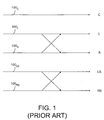
- MPEG-2 AAC standards Mid-Side (MS) Stereo Coding and Intensity Stereo Coding. Both the MS Stereo and Intensity Stereo coding methods operate on channel pairs, as shown in Figure 1. As shown in Figure 1, the signals in one channel pairs are denoted by ( 100 L , 100 R ) and ( 100 LS , 100 RS ).
- stereo audio coding The rationale behind the application of stereo audio coding is based on the fact that the human auditory system as well as a stereo recording system use two audio signal detectors. While a human being has two ears, a stereo recording system has two microphones. With these two audio signal detectors, the human auditory system or the stereo recording system receives and records an audio signal from the same source twice, once through each audio signal detector. The two sets of recorded data of the audio signal from the same source contain time and signal level differences caused mainly by the positions of the detectors in relation to the source.
- the human auditory system itself is able to detect and discard the inter-channel redundancy, thereby avoiding extra processing.
- the human auditory system locates sound sources mainly based on the inter-aural time difference (ITD) of the arrived signals.
- ITD inter-aural time difference
- ILD inter-aural level difference
- the psychoacoustic model analyzes the received signals with consecutive time blocks and determines for each block the spectral components of the received audio signal in the frequency domain in order to remove certain spectral components, thereby mimicking the masking properties of the human auditory system.
- the MPEG audio coder does not attempt to retain the input signal exactly after encoding and decoding, rather its goal is to reduce the amount of audio data yet maintaining the output signals similar to what the human auditory system might perceive.
- the MS Stereo coding technique applies a matrix to the signals of the (L,R) or (LS, RS) pair in order to compute the sum and difference of the two original signals, dealing mainly with the spectral image at the mid-frequency range.
- Intensity Stereo coding replaces the left and the right signals by a single representative signal plus directional information. The replacement of signals in the Intensity Stereo coding scheme is psychoacoustically justified in the higher frequency range at around 2kHz.
- the method can be advantageously applied to a surround sound system having a large number of sound channels (6 or more, for example).
- Such system and method can also be used in audio streaming over Internet Protocol (IP) for personal computer (PC) users, mobile IP and third-generation (3G) systems for mobile laptop users, digital radio, digital television, and digital archives of movie sound tracks and the like.
- IP Internet Protocol
- PC personal computer
- 3G third-generation
- the primary objective of the present invention is to improve the efficiency in encoding audio signals in a sound system in order to reduce the amount of audio data for transmission or storage.
- the first aspect of the present invention is a method of coding audio signals in a sound system having a plurality of sound channels for providing M sets of audio signals, wherein M is a positive integer greater than 2.
- the method comprises the steps of computing a first value representative of coding efficiency in intra-channel signal redundancy reduction in said audio signals; computing a second value representative of coding efficiency in inter-channel signal redundancy reduction in said audio signals; comparing the first value to the second value in order to select a more efficient coding process; and encoding the audio signals according to the selected process.
- the intra-channel signal redundancy reduction is carried out in accordance with a modified discrete cosine transform process
- the inter-channel signal redundancy reduction is carried out in accordance with a cascaded discrete cosine transform process.
- the inter-channel signal redundancy reduction is carried out in order to reduce redundancy in the audio signals among L channels, wherein L is a positive integer greater than 2 but smaller than M+1.
- the encoding step includes a signal masking process according to a psychoacoustic model simulating a human auditory system.
- the method further includes the step of converting the encoded signals into a bit stream.
- the second aspect of the present invention is an encoder for a sound system having a plurality of sound channels for providing M sets of audio signals, wherein M is a positive integer greater than 2.
- the encoder comprises a first mechanism, responsive to said audio signals, for providing a first reduced audio signal have a first magnitude indicative of a first data amount by removing intra-channel signal redundancy in said audio signals; a second mechanism, responsive to the first reduced audio signal, for providing a second reduced audio signal having a second magnitude indicative of a second data amount by removing inter-channel signal redundancy in said audio signals; and a third mechanism, responsive to the first audio signal and the second audio signal, for comparing the first and second data amounts for providing a third signal indicative of the reduced audio signal having a magnitude corresponding to the lesser data amount.
- the first mechanism removes the intra-channel signal redundancy by a modified discrete cosine transform process
- the second mechanism removes the inter-channel signal redundancy by a cascaded discrete cosine transform process in L of the M sets of audio signals, wherein L is a positive integer greater than 2 but smaller than M+1.
- the encoder also includes a mechanism for masking the audio signals according to a psychoacoustic model simulating a human auditory system.
- the encoder also includes a quantizer for quantizing the third signal into an encoded signal and a bit-stream formatter for converting the encoded signal into a bit-stream.
- the present invention improves the coding efficiency in audio coding for a sound system having M sound channels for sound reproduction, wherein M is greater than 2.
- the individual or intra-channel masking thresholds for each of the sound channels are calculated in a fashion similar to a basic Advanced Audio Coding (AAC) encoder.
- AAC Advanced Audio Coding
- This method is herein referred to as the intra-channel signal redundancy reduction method.
- DCT inter-channel discrete cosine transform
- This method is herein referred to as the cascaded MDCT-DCT coding method for inter-channel signal redundancy reduction.
- the MDCT-DCT coefficients should be quantized according to the highest threshold, taking into account the inter-channel masking effect, known as the masking level difference (MLD). This is characterized by a decreasing masking threshold when the masking mechanism is spatially separated from the source being masked.
- MLD masking level difference
- one of the audio coding steps of the present coding method is to perform an inter-channel DCT of multiple channel MDCT coefficients in a cascaded manner in order to reduce the inter-channel redundancy in an M channel sound system, wherein M is greater than 2.
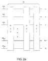
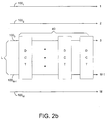
- Figures 2a and 2b diagrammatically illustrate M sound channels, and a group of DCT units 40 are used to perform inter-channel DCT from audio signals 100 1 , 100 2 , 100 3 ,.., 100 M+1 , and 100 M , When a block of N samples (the transform length) are used to compute a series of MDCT coefficients, the maximum number of DCT units 40 used to perform the inter-channel DCT is equal to the number of MDCT coefficients.
- the MDCT transform length N is determined by transform gain, computational complexity and the pre-echo problem; and the number of MDCT coefficients is N/2. Typically, the MDCT transform length N is between 256 and 2048 samples. Accordingly, the number of DCT units required to perform the inter-channel DCT is between 128 and 1024. In practice, however, the number of DCT units needed for performing the inter-channel DCT is much less.
- the cascaded MDCT-DCT is carried out with M DCT units 40 . It is also possible, however, to perform the inter-channel DCT of the MDCT coefficients of L channels, wherein L is a subset of M with L being greater than 2 and smaller than M+1. For example, in a 5-channel sound system consisting of left (L), right (R), center (C), left-surround (LS) and right-surround (RS) channels, it is possible to perform the cascaded inter-channel DCT of the MDCT coefficients involving only 4 channels, namely, L, R, LS and RS. Likewise, in a 12-channel sound system, it is possible to perform an inter-channel DCT of only 5 or 6 channel MDCT coefficients. As shown in Figure 2b, the cascaded MDCT-DCT is carried out with M-3 DCT units 40 in order to compute the cross correlation among audio signals 100 3 ,.., and 100 M+1 .
- the correlation in the audio signals among L (>2) channels is strong. Accordingly, the efficiency of audio coding using the cascaded MDCT-DCT method is higher than the efficiency of the intra-channel MDCT method alone. However, if the correlation in the audio signals among the L channels is weak, it is possible that this inter-channel DCT technique may not be as efficient as the intra-channel signal redundancy reduction using the MDCT coding method. Thus, it is advantageous to provide a comparison device to compare the coding efficiency of the two methods for each sampling block or a group of sampling blocks and select the more efficient method.
- Equations 1 and 2 The efficiency of the intra-channel MDCT coding method is represented by Equations 1 and 2 below.
- the MDCT coefficients in the frequency domain are given by:
- m represents a channel number
- M represents the number of sound channels involved.
- Equation 3 a cascaded inter-channel DCT of the M sets of MDCT coefficients should be performed, as given in Equations 3 and 4 below: It should be noted that the coefficient a(k) in Equation 1 and the coefficient a(k,j) in Equation 3 may include a modified function of sin( ⁇ k/N).
- Equation 5 the gain according to Equation 5 as follows: where L is the number of frames of the test signal used to calculate the average gain G. If G is positive, then the efficiency of the cascaded inter-channel DCT process is higher than the efficiency of the intra-channel MDCT process. Accordingly, the cascaded inter-channel DCT should be used for audio coding in order to reduce the amount of encoded data.
- the efficiency in the inter-channel signal redundancy reduction using the cascaded MDCT- DCT process can be evaluated using a cross-channel correlation method.
- the normalized cross-channel correlation coefficient between any two channels p and q is represented by the following equation:
- the absolute value of C pq can be used to set a threshold over which the cascaded MDCT-DCT process should be used.
- M(M-1)/2 normalized cross-channel correlation coefficients For example, in a three channel system having channels 1, 2 and 3, it is possible to calculate the normalized cross-channel correlation coefficients C 12 , C 13 , and C 23 .
- the sum of the absolute values of these normalized cross-channel con-elation coefficients can be used to compare the efficiency of the intra-channel MDCT method to the inter-channel cascaded MDCT-DCT method.
- the present invention provides a system for efficient audio coding to reduce redundancy in an M channel sound system, as shown in Figure 3.
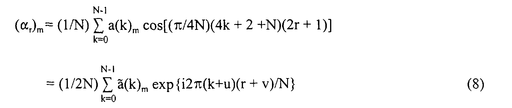
- the pulsed code modulation (PCM) samples 20 in the M channels are first conveyed to a set of M Shifted Discrete Fourier Transform (SDFT) devices 22 1 , 22 2 , .., 22 M so that the real parts of the SDFT coefficients form a group of M MDCT coefficients in a group of M MDCT units 30 1 , 30 2 , .., 30 M , respectively.
- the devices 22 1 , 22 2 , .., 22 M and the MDCT units 30 1 , 30 2 , .., 30 M together perform an intra-channel decorrelation.
- the right-hand side of Eq.8 is SDFT u,v ( ⁇ (k) m /2) or rea l ⁇ SDFT u,v (a(k) m /2) ⁇ .
- a number of DCT units 40 are used to compute the inter-channel signal redundancy reduction in these M sets of MDCT coefficients.
- the number of DCT units 40 can be equal to or less than the number of MDCT coefficients in each of the M channels, as discussed earlier in conjunction with Equation 3.
- a comparison device 50 is used to compute the gain G (Equation 5) or the threshold from the cross-channel correlation coefficients C pq (Equation 6) to ensure that the coding according to the cascaded inter-channel DCT of the MDCT coefficients is more efficient than the intra-channel decorrelation by the MDCT units 30 1 , 30 2 , .., 30 M .
- a masking mechanism 52 based on a so-called psychoacoustic model, is used to remove the audio data believed not to be used by a human auditory system. As shown in Figure 3, the masking mechanism is also operatively connected to the comparison device 50 so that the masking is carried out according to the intra-channel MDCT manner or the inter-channel MDCT-DCT manner.
- the 2-D spectral image is quantized by a group of quantizers 60 1 , 60 2 , .., 60 M according to the masking threshold calculated by the psychoacoustic model and the quantized data is further processed by a bit stream formatter 70 into a bit stream 80 for transmission or storage.
- the efficiency of the cascaded MDCT-DCT coding process in removing cross-channel redundancy increases with the number of sound channels involved. For example, if a sound system consists of 6 or more surround sound speakers, then the reduction in cross-channel redundancy using the cascaded MDCT-DCT processing is usually significant. However, if the number of channels to be used in the cascaded MDCT-DCT processing is 2, then the efficiency may not be improved at all. It should be noted that, like any perceptual audio coder, the goal of the cascaded MDCT-DCT processing is to reduce the audio data for transmission or storage. While the processing method is intended to produce signal outputs similar to what a human auditory system might perceive, its goal is not to replicate the input signals.
- the so-called psychoacoustic model may consist of a certain perceptual model and a certain band mapping model.
- the surround sound encoding system may consist of components such as an AAC gain control and a certain long-term prediction model.
- these components are well-known in the art and they can be modified, replaced or omitted.
Landscapes
- Engineering & Computer Science (AREA)
- Physics & Mathematics (AREA)
- Signal Processing (AREA)
- Multimedia (AREA)
- Computational Linguistics (AREA)
- Health & Medical Sciences (AREA)
- Audiology, Speech & Language Pathology (AREA)
- Human Computer Interaction (AREA)
- Acoustics & Sound (AREA)
- Mathematical Physics (AREA)
- Spectroscopy & Molecular Physics (AREA)
- Compression, Expansion, Code Conversion, And Decoders (AREA)
- Transmission Systems Not Characterized By The Medium Used For Transmission (AREA)
- Analogue/Digital Conversion (AREA)
Abstract
Description
The driving force to develop the AAC algorithm has been the quest for an efficient coding method for surround sound signals, such as 5-channel signals including left (L), right (R), center (C), left-surround (LS) and right-surround (RS) signals. MPEG-2 AAC basically makes use of the signal masking properties of the human ear in order to reduce the amount of data. Generally, an N-channel surround sound system, running with a bit rate of M bps/ch does not necessarily have a total bit rate of MxN bps, but rather an overall bit rate significantly less than MxN bps due to cross channel (inter-channel) redundancy. To exploit the inter-channel redundancy, two methods have been used in MPEG-2 AAC standards: Mid-Side (MS) Stereo Coding and Intensity Stereo Coding. Both the MS Stereo and Intensity Stereo coding methods operate on channel pairs, as shown in Figure 1. As shown in Figure 1, the signals in one channel pairs are denoted by (100 L, 100 R) and (100 LS, 100 RS). The rationale behind the application of stereo audio coding is based on the fact that the human auditory system as well as a stereo recording system use two audio signal detectors. While a human being has two ears, a stereo recording system has two microphones. With these two audio signal detectors, the human auditory system or the stereo recording system receives and records an audio signal from the same source twice, once through each audio signal detector. The two sets of recorded data of the audio signal from the same source contain time and signal level differences caused mainly by the positions of the detectors in relation to the source.






Claims (12)
- A method of coding audio signals in a sound system having a plurality of sound channels for providing M sets of audio signals, wherein M is a positive integer greater than 2, said method comprising the steps of:computing a first value representative of coding efficiency in intra-channel signal redundancy reduction in said audio signals;computing a second value representative of coding efficiency in inter-channel signal redundancy reduction in said audio signals;comparing the first value to the second value in order to select a more efficient coding process; andencoding the audio signals according to the selected process.
- The method of claim 1, wherein the intra-channel signal redundancy reduction is carried out in accordance with a modified discrete cosine transform process, and the inter-channel signal redundancy reduction is carried out in accordance with a cascaded discrete cosine transform process.
- The method of claim 1, wherein the inter-channel signal redundancy reduction is carried out in order to reduce redundancy in the audio signals among L channels, wherein L is a positive integer greater than 2 but smaller than M+1.
- The method of claim 1, wherein the encoding step includes a signal masking process according to a psychoacoustic model simulating a human auditory system.
- The method of claim 1, further comprising the step of converting the encoded signals into a bit stream.
- An encoding apparatus for a sound system having a plurality of sound channels for providing M sets of audio signals, wherein M is a positive integer greater than 2, said encoding apparatus comprising:first means, responsive to said audio signals, for providing a first reduced audio signal have a first magnitude indicative of a first data amount by removing intra-channel signal redundancy in said audio signals;second means, responsive to the first reduced audio signal, for providing a second reduced audio signal have a second magnitude indicative of a second data amount by removing inter-channel signal redundancy in said audio signals; andthird means, responsive to the first audio signal and the second audio signal, for comparing the first and second data amounts for providing a third signal indicative of the reduced audio signal having a magnitude corresponding to the lesser data amount.
- The encoding apparatus of claim 6, wherein the first means removes the intra-channel signal redundancy by a modified discrete cosine transform process, and the second means removes the inter-channel signal redundancy by a cascaded discrete cosine transform process.
- The encoding apparatus of claim 6, wherein the second means removes the inter-channel signal redundancy in L of the M sets of audio signals and wherein L is a positive integer greater than 2 but smaller than M+1.
- The encoding apparatus of claim 6, further comprising a mechanism for masking the audio signals according to a psychoacoustic model simulating a human auditory system.
- The encoding apparatus of claim 6, further comprising a mechanism for quantizing the third signal into an encoded signal.
- The encoding apparatus of claim 10, further comprising a mechanism for converting the encoded signal into a bit stream.
- The encoding apparatus of claim 6, wherein the third means is capable of computing a value indicative of cross-channel correlation coefficients among the M sets of audio signals and comparing said value to a pre-determined threshold in order to compare the first and second data amounts.
Applications Claiming Priority (2)
| Application Number | Priority Date | Filing Date | Title |
|---|---|---|---|
| US61220700A | 2000-07-07 | 2000-07-07 | |
| US612207 | 2000-07-07 |
Publications (3)
| Publication Number | Publication Date |
|---|---|
| EP1175030A2 true EP1175030A2 (en) | 2002-01-23 |
| EP1175030A3 EP1175030A3 (en) | 2002-10-23 |
| EP1175030B1 EP1175030B1 (en) | 2008-02-20 |
Family
ID=24452190
Family Applications (1)
| Application Number | Title | Priority Date | Filing Date |
|---|---|---|---|
| EP01305191A Expired - Lifetime EP1175030B1 (en) | 2000-07-07 | 2001-06-14 | Method and system for multichannel perceptual audio coding using the cascaded discrete cosine transform or modified discrete cosine transform |
Country Status (3)
| Country | Link |
|---|---|
| EP (1) | EP1175030B1 (en) |
| AT (1) | ATE387044T1 (en) |
| DE (1) | DE60132853D1 (en) |
Cited By (13)
| Publication number | Priority date | Publication date | Assignee | Title |
|---|---|---|---|---|
| EP2028648A2 (en) | 2002-09-04 | 2009-02-25 | Microsoft Corporation | Multi-channel audio encoding and decoding |
| US7801735B2 (en) | 2002-09-04 | 2010-09-21 | Microsoft Corporation | Compressing and decompressing weight factors using temporal prediction for audio data |
| US7831434B2 (en) | 2006-01-20 | 2010-11-09 | Microsoft Corporation | Complex-transform channel coding with extended-band frequency coding |
| US7930171B2 (en) | 2001-12-14 | 2011-04-19 | Microsoft Corporation | Multi-channel audio encoding/decoding with parametric compression/decompression and weight factors |
| WO2011060816A1 (en) * | 2009-11-18 | 2011-05-26 | Nokia Corporation | Data processing |
| US7953604B2 (en) | 2006-01-20 | 2011-05-31 | Microsoft Corporation | Shape and scale parameters for extended-band frequency coding |
| US8046214B2 (en) * | 2007-06-22 | 2011-10-25 | Microsoft Corporation | Low complexity decoder for complex transform coding of multi-channel sound |
| US8069052B2 (en) | 2002-09-04 | 2011-11-29 | Microsoft Corporation | Quantization and inverse quantization for audio |
| EP2410518A1 (en) * | 2010-07-22 | 2012-01-25 | Samsung Electronics Co., Ltd. | Apparatus and method for encoding and decoding multi-channel audio signal |
| CN101896966B (en) * | 2007-12-13 | 2012-11-21 | 高通股份有限公司 | Fast algorithms for computation of 5-point dct-II, dct-IV, and dst-IV, and architectures |
| US9741354B2 (en) | 2007-06-29 | 2017-08-22 | Microsoft Technology Licensing, Llc | Bitstream syntax for multi-process audio decoding |
| US10410644B2 (en) | 2011-03-28 | 2019-09-10 | Dolby Laboratories Licensing Corporation | Reduced complexity transform for a low-frequency-effects channel |
| WO2022247651A1 (en) * | 2021-05-28 | 2022-12-01 | 华为技术有限公司 | Encoding method and apparatus for multi-channel audio signals |
Families Citing this family (4)
| Publication number | Priority date | Publication date | Assignee | Title |
|---|---|---|---|---|
| US7240001B2 (en) | 2001-12-14 | 2007-07-03 | Microsoft Corporation | Quality improvement techniques in an audio encoder |
| US7460990B2 (en) | 2004-01-23 | 2008-12-02 | Microsoft Corporation | Efficient coding of digital media spectral data using wide-sense perceptual similarity |
| US8190425B2 (en) | 2006-01-20 | 2012-05-29 | Microsoft Corporation | Complex cross-correlation parameters for multi-channel audio |
| US8249883B2 (en) | 2007-10-26 | 2012-08-21 | Microsoft Corporation | Channel extension coding for multi-channel source |
Family Cites Families (7)
| Publication number | Priority date | Publication date | Assignee | Title |
|---|---|---|---|---|
| DE4331376C1 (en) * | 1993-09-15 | 1994-11-10 | Fraunhofer Ges Forschung | Method for determining the type of encoding to selected for the encoding of at least two signals |
| US5488665A (en) * | 1993-11-23 | 1996-01-30 | At&T Corp. | Multi-channel perceptual audio compression system with encoding mode switching among matrixed channels |
| JP3404837B2 (en) * | 1993-12-07 | 2003-05-12 | ソニー株式会社 | Multi-layer coding device |
| KR970005131B1 (en) * | 1994-01-18 | 1997-04-12 | 대우전자 주식회사 | Digital Audio Coding Device Adaptive to Human Auditory Characteristics |
| EP0688113A2 (en) * | 1994-06-13 | 1995-12-20 | Sony Corporation | Method and apparatus for encoding and decoding digital audio signals and apparatus for recording digital audio |
| US5812971A (en) * | 1996-03-22 | 1998-09-22 | Lucent Technologies Inc. | Enhanced joint stereo coding method using temporal envelope shaping |
| DE19628292B4 (en) * | 1996-07-12 | 2007-08-02 | Fraunhofer-Gesellschaft zur Förderung der angewandten Forschung e.V. | Method for coding and decoding stereo audio spectral values |
-
2001
- 2001-06-14 EP EP01305191A patent/EP1175030B1/en not_active Expired - Lifetime
- 2001-06-14 AT AT01305191T patent/ATE387044T1/en not_active IP Right Cessation
- 2001-06-14 DE DE60132853T patent/DE60132853D1/en not_active Expired - Lifetime
Cited By (17)
| Publication number | Priority date | Publication date | Assignee | Title |
|---|---|---|---|---|
| US7930171B2 (en) | 2001-12-14 | 2011-04-19 | Microsoft Corporation | Multi-channel audio encoding/decoding with parametric compression/decompression and weight factors |
| US8069052B2 (en) | 2002-09-04 | 2011-11-29 | Microsoft Corporation | Quantization and inverse quantization for audio |
| EP2028648A2 (en) | 2002-09-04 | 2009-02-25 | Microsoft Corporation | Multi-channel audio encoding and decoding |
| EP2028648A3 (en) * | 2002-09-04 | 2009-04-29 | Microsoft Corporation | Multi-channel audio encoding and decoding |
| US7801735B2 (en) | 2002-09-04 | 2010-09-21 | Microsoft Corporation | Compressing and decompressing weight factors using temporal prediction for audio data |
| US7831434B2 (en) | 2006-01-20 | 2010-11-09 | Microsoft Corporation | Complex-transform channel coding with extended-band frequency coding |
| US7953604B2 (en) | 2006-01-20 | 2011-05-31 | Microsoft Corporation | Shape and scale parameters for extended-band frequency coding |
| US8046214B2 (en) * | 2007-06-22 | 2011-10-25 | Microsoft Corporation | Low complexity decoder for complex transform coding of multi-channel sound |
| US9741354B2 (en) | 2007-06-29 | 2017-08-22 | Microsoft Technology Licensing, Llc | Bitstream syntax for multi-process audio decoding |
| TWI405185B (en) * | 2007-12-13 | 2013-08-11 | Qualcomm Inc | Fast algorithm and structure for the calculation of 5-point discrete cosine transform-II (DCT-II), discrete cosine transform-IV (DCT-IV) and discrete sine transform-IV (DST-IV) |
| CN101896966B (en) * | 2007-12-13 | 2012-11-21 | 高通股份有限公司 | Fast algorithms for computation of 5-point dct-II, dct-IV, and dst-IV, and architectures |
| US8631060B2 (en) | 2007-12-13 | 2014-01-14 | Qualcomm Incorporated | Fast algorithms for computation of 5-point DCT-II, DCT-IV, and DST-IV, and architectures |
| WO2011060816A1 (en) * | 2009-11-18 | 2011-05-26 | Nokia Corporation | Data processing |
| EP2410518A1 (en) * | 2010-07-22 | 2012-01-25 | Samsung Electronics Co., Ltd. | Apparatus and method for encoding and decoding multi-channel audio signal |
| US9305556B2 (en) | 2010-07-22 | 2016-04-05 | Samsung Electronics Co., Ltd. | Apparatus and method for encoding and decoding multi-channel audio signal |
| US10410644B2 (en) | 2011-03-28 | 2019-09-10 | Dolby Laboratories Licensing Corporation | Reduced complexity transform for a low-frequency-effects channel |
| WO2022247651A1 (en) * | 2021-05-28 | 2022-12-01 | 华为技术有限公司 | Encoding method and apparatus for multi-channel audio signals |
Also Published As
| Publication number | Publication date |
|---|---|
| EP1175030B1 (en) | 2008-02-20 |
| DE60132853D1 (en) | 2008-04-03 |
| ATE387044T1 (en) | 2008-03-15 |
| EP1175030A3 (en) | 2002-10-23 |
Similar Documents
| Publication | Publication Date | Title |
|---|---|---|
| US6934676B2 (en) | Method and system for inter-channel signal redundancy removal in perceptual audio coding | |
| CA2197128C (en) | Enhanced joint stereo coding method using temporal envelope shaping | |
| EP1175030B1 (en) | Method and system for multichannel perceptual audio coding using the cascaded discrete cosine transform or modified discrete cosine transform | |
| Davis | The AC-3 multichannel coder | |
| EP1210712B1 (en) | Scalable coding method for high quality audio | |
| JP3926399B2 (en) | How to signal noise substitution during audio signal coding | |
| US8065136B2 (en) | Multi-channel encoder | |
| KR960012475B1 (en) | Digital audio coder of channel bit | |
| EP1479071B1 (en) | Parametric audio coding | |
| EP0714173B1 (en) | Method and device for encoding signal, method and device for decoding signal, recording medium, and signal transmitting method | |
| US20070271095A1 (en) | Audio Encoder | |
| KR100528325B1 (en) | Scalable stereo audio coding/encoding method and apparatus thereof | |
| CN101673545B (en) | Method and device for coding and decoding | |
| KR100952065B1 (en) | Encoding method and apparatus, and decoding method and apparatus | |
| KR100682915B1 (en) | Multi-channel signal encoding / decoding method and apparatus | |
| JP2852862B2 (en) | Method and apparatus for converting PCM audio signal | |
| KR20080066537A (en) | Method and apparatus for encoding / decoding audio signal having additional information | |
| WO1995016263A1 (en) | Information processing method, information processing device and media | |
| JPH08123488A (en) | High efficiency coding method, high efficiency code recording method, high efficiency code transmission method, high efficiency coding device, and high efficiency code decoding method | |
| JPH09135173A (en) | Encoding apparatus and encoding method, decoding apparatus and decoding method, transmission apparatus and transmission method, and recording medium | |
| JP3854313B2 (en) | Encoding multiple information signals | |
| KR100685974B1 (en) | Apparatus and method for watermark insertion / detection | |
| KR960003455B1 (en) | Ms stereo digital audio coder and decoder with bit assortment | |
| KR20080010981A (en) | Data Encoding / Decoding Method | |
| JPH07161140A (en) | Digital audio signal transmitting apparatus and receiving apparatus, and digital audio signal transmitting method and receiving method |
Legal Events
| Date | Code | Title | Description |
|---|---|---|---|
| PUAI | Public reference made under article 153(3) epc to a published international application that has entered the european phase |
Free format text: ORIGINAL CODE: 0009012 |
|
| AK | Designated contracting states |
Kind code of ref document: A2 Designated state(s): AT BE CH CY DE DK ES FI FR GB GR IE IT LI LU MC NL PT SE TR |
|
| AX | Request for extension of the european patent |
Free format text: AL;LT;LV;MK;RO;SI |
|
| RAP1 | Party data changed (applicant data changed or rights of an application transferred) |
Owner name: NOKIA CORPORATION |
|
| PUAL | Search report despatched |
Free format text: ORIGINAL CODE: 0009013 |
|
| AK | Designated contracting states |
Kind code of ref document: A3 Designated state(s): AT BE CH CY DE DK ES FI FR GB GR IE IT LI LU MC NL PT SE TR |
|
| AX | Request for extension of the european patent |
Free format text: AL;LT;LV;MK;RO;SI |
|
| 17P | Request for examination filed |
Effective date: 20030327 |
|
| AKX | Designation fees paid |
Designated state(s): AT BE CH CY DE DK ES FI FR GB GR IE IT LI LU MC NL PT SE TR |
|
| 17Q | First examination report despatched |
Effective date: 20050324 |
|
| 17Q | First examination report despatched |
Effective date: 20050324 |
|
| GRAP | Despatch of communication of intention to grant a patent |
Free format text: ORIGINAL CODE: EPIDOSNIGR1 |
|
| GRAS | Grant fee paid |
Free format text: ORIGINAL CODE: EPIDOSNIGR3 |
|
| GRAA | (expected) grant |
Free format text: ORIGINAL CODE: 0009210 |
|
| AK | Designated contracting states |
Kind code of ref document: B1 Designated state(s): AT BE CH CY DE DK ES FI FR GB GR IE IT LI LU MC NL PT SE TR |
|
| RAP1 | Party data changed (applicant data changed or rights of an application transferred) |
Owner name: NOKIA SIEMENS NETWORKS OY |
|
| REG | Reference to a national code |
Ref country code: GB Ref legal event code: FG4D |
|
| REG | Reference to a national code |
Ref country code: CH Ref legal event code: EP |
|
| REG | Reference to a national code |
Ref country code: IE Ref legal event code: FG4D |
|
| REF | Corresponds to: |
Ref document number: 60132853 Country of ref document: DE Date of ref document: 20080403 Kind code of ref document: P |
|
| REG | Reference to a national code |
Ref country code: SE Ref legal event code: TRGR |
|
| PG25 | Lapsed in a contracting state [announced via postgrant information from national office to epo] |
Ref country code: FI Free format text: LAPSE BECAUSE OF FAILURE TO SUBMIT A TRANSLATION OF THE DESCRIPTION OR TO PAY THE FEE WITHIN THE PRESCRIBED TIME-LIMIT Effective date: 20080220 Ref country code: ES Free format text: LAPSE BECAUSE OF FAILURE TO SUBMIT A TRANSLATION OF THE DESCRIPTION OR TO PAY THE FEE WITHIN THE PRESCRIBED TIME-LIMIT Effective date: 20080531 |
|
| NLV1 | Nl: lapsed or annulled due to failure to fulfill the requirements of art. 29p and 29m of the patents act | ||
| PG25 | Lapsed in a contracting state [announced via postgrant information from national office to epo] |
Ref country code: AT Free format text: LAPSE BECAUSE OF FAILURE TO SUBMIT A TRANSLATION OF THE DESCRIPTION OR TO PAY THE FEE WITHIN THE PRESCRIBED TIME-LIMIT Effective date: 20080220 |
|
| PG25 | Lapsed in a contracting state [announced via postgrant information from national office to epo] |
Ref country code: BE Free format text: LAPSE BECAUSE OF FAILURE TO SUBMIT A TRANSLATION OF THE DESCRIPTION OR TO PAY THE FEE WITHIN THE PRESCRIBED TIME-LIMIT Effective date: 20080220 |
|
| PG25 | Lapsed in a contracting state [announced via postgrant information from national office to epo] |
Ref country code: PT Free format text: LAPSE BECAUSE OF FAILURE TO SUBMIT A TRANSLATION OF THE DESCRIPTION OR TO PAY THE FEE WITHIN THE PRESCRIBED TIME-LIMIT Effective date: 20080721 Ref country code: NL Free format text: LAPSE BECAUSE OF FAILURE TO SUBMIT A TRANSLATION OF THE DESCRIPTION OR TO PAY THE FEE WITHIN THE PRESCRIBED TIME-LIMIT Effective date: 20080220 Ref country code: DK Free format text: LAPSE BECAUSE OF FAILURE TO SUBMIT A TRANSLATION OF THE DESCRIPTION OR TO PAY THE FEE WITHIN THE PRESCRIBED TIME-LIMIT Effective date: 20080220 |
|
| EN | Fr: translation not filed | ||
| PLBE | No opposition filed within time limit |
Free format text: ORIGINAL CODE: 0009261 |
|
| STAA | Information on the status of an ep patent application or granted ep patent |
Free format text: STATUS: NO OPPOSITION FILED WITHIN TIME LIMIT |
|
| 26N | No opposition filed |
Effective date: 20081121 |
|
| PG25 | Lapsed in a contracting state [announced via postgrant information from national office to epo] |
Ref country code: MC Free format text: LAPSE BECAUSE OF NON-PAYMENT OF DUE FEES Effective date: 20080630 Ref country code: DE Free format text: LAPSE BECAUSE OF FAILURE TO SUBMIT A TRANSLATION OF THE DESCRIPTION OR TO PAY THE FEE WITHIN THE PRESCRIBED TIME-LIMIT Effective date: 20080521 |
|
| REG | Reference to a national code |
Ref country code: CH Ref legal event code: PL |
|
| PG25 | Lapsed in a contracting state [announced via postgrant information from national office to epo] |
Ref country code: IE Free format text: LAPSE BECAUSE OF NON-PAYMENT OF DUE FEES Effective date: 20080616 Ref country code: FR Free format text: LAPSE BECAUSE OF FAILURE TO SUBMIT A TRANSLATION OF THE DESCRIPTION OR TO PAY THE FEE WITHIN THE PRESCRIBED TIME-LIMIT Effective date: 20081212 |
|
| PG25 | Lapsed in a contracting state [announced via postgrant information from national office to epo] |
Ref country code: CH Free format text: LAPSE BECAUSE OF NON-PAYMENT OF DUE FEES Effective date: 20080630 Ref country code: LI Free format text: LAPSE BECAUSE OF NON-PAYMENT OF DUE FEES Effective date: 20080630 |
|
| PG25 | Lapsed in a contracting state [announced via postgrant information from national office to epo] |
Ref country code: CY Free format text: LAPSE BECAUSE OF FAILURE TO SUBMIT A TRANSLATION OF THE DESCRIPTION OR TO PAY THE FEE WITHIN THE PRESCRIBED TIME-LIMIT Effective date: 20080220 |
|
| PG25 | Lapsed in a contracting state [announced via postgrant information from national office to epo] |
Ref country code: IT Free format text: LAPSE BECAUSE OF FAILURE TO SUBMIT A TRANSLATION OF THE DESCRIPTION OR TO PAY THE FEE WITHIN THE PRESCRIBED TIME-LIMIT Effective date: 20080220 |
|
| PG25 | Lapsed in a contracting state [announced via postgrant information from national office to epo] |
Ref country code: LU Free format text: LAPSE BECAUSE OF NON-PAYMENT OF DUE FEES Effective date: 20080614 |
|
| PG25 | Lapsed in a contracting state [announced via postgrant information from national office to epo] |
Ref country code: TR Free format text: LAPSE BECAUSE OF FAILURE TO SUBMIT A TRANSLATION OF THE DESCRIPTION OR TO PAY THE FEE WITHIN THE PRESCRIBED TIME-LIMIT Effective date: 20080220 |
|
| PG25 | Lapsed in a contracting state [announced via postgrant information from national office to epo] |
Ref country code: GR Free format text: LAPSE BECAUSE OF FAILURE TO SUBMIT A TRANSLATION OF THE DESCRIPTION OR TO PAY THE FEE WITHIN THE PRESCRIBED TIME-LIMIT Effective date: 20080521 |
|
| PGFP | Annual fee paid to national office [announced via postgrant information from national office to epo] |
Ref country code: SE Payment date: 20100614 Year of fee payment: 10 Ref country code: GB Payment date: 20100618 Year of fee payment: 10 |
|
| REG | Reference to a national code |
Ref country code: SE Ref legal event code: EUG |
|
| GBPC | Gb: european patent ceased through non-payment of renewal fee |
Effective date: 20110614 |
|
| PG25 | Lapsed in a contracting state [announced via postgrant information from national office to epo] |
Ref country code: GB Free format text: LAPSE BECAUSE OF NON-PAYMENT OF DUE FEES Effective date: 20110614 |
|
| PG25 | Lapsed in a contracting state [announced via postgrant information from national office to epo] |
Ref country code: SE Free format text: LAPSE BECAUSE OF NON-PAYMENT OF DUE FEES Effective date: 20110615 |