EP1174999A2 - Sensorless motor driving apparatus - Google Patents
Sensorless motor driving apparatus Download PDFInfo
- Publication number
- EP1174999A2 EP1174999A2 EP01117135A EP01117135A EP1174999A2 EP 1174999 A2 EP1174999 A2 EP 1174999A2 EP 01117135 A EP01117135 A EP 01117135A EP 01117135 A EP01117135 A EP 01117135A EP 1174999 A2 EP1174999 A2 EP 1174999A2
- Authority
- EP
- European Patent Office
- Prior art keywords
- commutation
- reference point
- motor
- time
- routine
- Prior art date
- Legal status (The legal status is an assumption and is not a legal conclusion. Google has not performed a legal analysis and makes no representation as to the accuracy of the status listed.)
- Withdrawn
Links
- 230000005284 excitation Effects 0.000 claims abstract description 35
- 230000033001 locomotion Effects 0.000 claims abstract description 14
- 230000004044 response Effects 0.000 claims abstract description 9
- 238000001514 detection method Methods 0.000 claims description 20
- 230000001186 cumulative effect Effects 0.000 description 75
- 238000000034 method Methods 0.000 description 9
- 230000008859 change Effects 0.000 description 6
- 238000010586 diagram Methods 0.000 description 6
- 230000032683 aging Effects 0.000 description 2
- 230000005540 biological transmission Effects 0.000 description 2
- 238000004891 communication Methods 0.000 description 2
- 230000008569 process Effects 0.000 description 2
- 238000010276 construction Methods 0.000 description 1
- 238000007796 conventional method Methods 0.000 description 1
- 230000003111 delayed effect Effects 0.000 description 1
- 230000001419 dependent effect Effects 0.000 description 1
- 238000009434 installation Methods 0.000 description 1
- 230000007246 mechanism Effects 0.000 description 1
- 230000007935 neutral effect Effects 0.000 description 1
- 230000003287 optical effect Effects 0.000 description 1
Images




Classifications
-
- H—ELECTRICITY
- H02—GENERATION; CONVERSION OR DISTRIBUTION OF ELECTRIC POWER
- H02P—CONTROL OR REGULATION OF ELECTRIC MOTORS, ELECTRIC GENERATORS OR DYNAMO-ELECTRIC CONVERTERS; CONTROLLING TRANSFORMERS, REACTORS OR CHOKE COILS
- H02P8/00—Arrangements for controlling dynamo-electric motors rotating step by step
- H02P8/14—Arrangements for controlling speed or speed and torque
-
- H—ELECTRICITY
- H02—GENERATION; CONVERSION OR DISTRIBUTION OF ELECTRIC POWER
- H02P—CONTROL OR REGULATION OF ELECTRIC MOTORS, ELECTRIC GENERATORS OR DYNAMO-ELECTRIC CONVERTERS; CONTROLLING TRANSFORMERS, REACTORS OR CHOKE COILS
- H02P6/00—Arrangements for controlling synchronous motors or other dynamo-electric motors using electronic commutation dependent on the rotor position; Electronic commutators therefor
- H02P6/14—Electronic commutators
- H02P6/16—Circuit arrangements for detecting position
- H02P6/18—Circuit arrangements for detecting position without separate position detecting elements
- H02P6/182—Circuit arrangements for detecting position without separate position detecting elements using back-emf in windings
-
- H—ELECTRICITY
- H02—GENERATION; CONVERSION OR DISTRIBUTION OF ELECTRIC POWER
- H02P—CONTROL OR REGULATION OF ELECTRIC MOTORS, ELECTRIC GENERATORS OR DYNAMO-ELECTRIC CONVERTERS; CONTROLLING TRANSFORMERS, REACTORS OR CHOKE COILS
- H02P6/00—Arrangements for controlling synchronous motors or other dynamo-electric motors using electronic commutation dependent on the rotor position; Electronic commutators therefor
- H02P6/20—Arrangements for starting
- H02P6/21—Open loop start
Definitions
- the present invention relates to an apparatus for driving a sensorless motor such as a brushless DC motor or a stepper motor, and more particularly, to an apparatus for driving a sensorless motor by controlling commutation by means of a position detector disposed on an object driven by the motor.
- the counter electromotive voltage induced in a not excited coil is monitored, and the position of the rotor is detected by detecting a zero-crossing point at which the counter electromotive voltage crosses a neutral voltage point.
- commutation is performed, for example, at a point at which the phase is shifted by 30° with respect to the zero-crossing point.
- a pulse signal is output from the position detector in response to the movement of the object, and commutation is controlled on the basis of the counted number of pulses (or pulse edges) of the pulse signal.
- the commutation reference point which is used as a reference point in counting the number of pulses, is set by the commutation reference point setting means on the basis of a position (pulled-in position) at which the rotor stops when a stator coil of the motor is excited for the first time.
- commutation reference points are set for the respective rotation directions of the motor.
- the absolute position of the rotor corresponding to a certain absolute position of the object becomes different depending upon the rotation direction, because the amount of expansion of the belt varies depending upon the rotation direction.
- commutation reference points are set for the respective rotation directions of the motor, and commutation is controlled, depending upon the present rotation direction, in accordance with the number of pulses as counted starting from the commutation reference point set for the present rotation direction, thereby preventing the commutation timings from shifting from the correct timings.
- an offset value which indicates the number of pulses corresponding to the difference in position between the commutation reference points set for the respective rotation directions of the motor, is detected, and the number of pulses is counted with respect to one of commutation reference points and the counted value of pulses is corrected on the basis of the offset value each time the rotation direction is switched so that the resultant number of pulses represents a correct number with respect to the commutation reference point for the corresponding rotation direction.
- the counter electromotive force induced in the not excited phase, in which no current is passed, of the motor is detected by the counter electromotive force detection means.
- the position of the rotor is detected on the basis of the detected counter electromotive force, and a commutation timing is generated on the basis of the detected position of the rotor.
- resetting of the commutation reference point is performed.
- the accuracy of the position of the rotor detected on the basis of the counter electromotive force is better than the accuracy of the position of the rotor detected on the basis of the pulled-in position where the rotor is pulled in by pulling-in excitation. That is, in the case where the rotor is pulled into a rest position by excitation, the rotor stops at a position slightly shifted from an electrical stable rest position, depending upon an external force such as a frictional force which is balanced with the torque generated by the motor. In contrast, the position of the rotor detected by the counter electromotive force does not include an error caused by a frictional force or the like.
- the position of the rotor is detected more precisely on the basis of the counter electromotive force, and a commutation timing is generated on the basis of the detected position of the rotor, and resetting of commutation reference point is performed.
- the number of pulses is counted with respect to the commutation reference point, and commutation is performed on the basis of the counted value of pulses, and thus it is ensured that commutation is controlled more precisely.
- the commutation timing generating means generates commutation timings on the basis of the counter electromotive force not of all phases of the sensorless motor but of one of the phases, and thus the counter electromotive force can be detected using a fewer number of circuits, and the commutation timing can be generated by simpler processing.
- the commutation reference point setting means resets the commutation reference points on the basis of the commutation timings generated for the respective rotation directions by the commutation timing generating means.
- the absolute position of the rotor corresponding to a certain absolute position of the object becomes different depending upon the rotation direction, because the amount of expansion of the belt varies depending upon the rotation direction.
- commutation timings are generated on the basis of the counter electromotive forces in the respective rotation directions, and resetting of the commutation reference points is performed for the respective rotation directions on the basis of the commutation timings generated, thereby preventing the commutation timings from shifting from the correct timings.
- an offset value is detected which indicates the number of pulses corresponding to the difference in position between the commutation reference points set for the respective rotation directions of the sensorless motor, and the detected offset value is stored in the storage means.
- the number of pulses is counted with respect to one of the commutation reference points, and the counted value of pulses is corrected on the basis of the offset value stored in the storage means each time the rotation direction is switched, so that the corrected counted value represents the number with respect to the commutation reference point corresponding to the present rotation direction.
- the resetting of the commutation reference point on the basis of the commutation timing generated by the commutation timing generating means is performed when the control of the motor is started, and the commutation reference point is reset as soon as the rotation speed of the motor becomes high enough to generate a commutation timing on the basis of counter electromotive force. Therefore, the commutation reference point can be set precisely in early stage after starting the control of the motor.
- the resetting of the commutation reference point is performed when a predetermined period of time has elapsed since the control was started, more specifically, for example, if the resetting is performed when a change in the ambient temperature, which occurs after the motor is started, has reached an equilibrium state, the resetting of the commutation reference point is performed under a stable condition in terms of the ambient temperature. Furthermore, if the resetting of the commutation reference point is performed each time a predetermined period of time elapses after the control is started, the commutation reference point is properly set depending upon a change in ambient temperature. Still furthermore, if the resetting of the commutation reference point is performed each time the motor is started, that is, each time the rotor starts to rotate, the commutation reference point is correctly set depending upon the conditions when the motor is started.
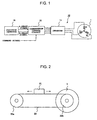
- Fig. 1 is a schematic diagram of a driver circuit 10 for driving a brushless motor 1, according to the present invention.
- the motor 1 is a 3-phase sensorless motor having three star-connected stator coils of phases of U, V, and W.
- the driver circuit 10 includes an inverter 11, output terminals of which are connected to respective terminals of phases of U, V, and W of the motor 1.
- the inverter 11 includes three pairs of transistors connected in a known manner to form three half-bridges, one for each phase. Each half-bridge is composed of a series connection of two transistors connected between a power source terminal and ground. The turning-on/off of the six transistors in the inverter is controlled by commutation signals supplied from a commutation control circuit 12 so that the respective phases of the motor 1 are sequentially excited to rotate the rotor.
- the rotary shaft of the motor 1 is connected to, for example, a carriage moving mechanism of a printer via a pulley.
- a carriage 21 is disposed on a belt 23 extending between two pulleys 22a and 22b such that the carriage 21 is moved via the belt 23 by transmitting a rotational force of the motor 1 to one of pulleys 22b.
- the carriage 21 includes a position detector 15 such as a linear encoder for detecting the position of the carriage, and the commutation of the motor 1 is controlled on the basis of encoder pulses output from the position detector 15.
- a position detector 15 such as a linear encoder for detecting the position of the carriage, and the commutation of the motor 1 is controlled on the basis of encoder pulses output from the position detector 15.
- the commutation control circuit 12 includes, for example, a microcomputer and a storage device (storage means) for storing data such as a predetermined commutation constant T which will be described later.
- Two detection signals are output from the position detector 15 and applied to the commutation control circuit 12.
- This pulled-in position is employed as a commutation reference point in determining commutation timings, and a cumulative value S, a count variable kept in commutation control circuit 12, is set to "0" when the rotor is pulled-in at this commutation reference point.
- the commutation constant T is added to or subtracted from the cumulative value S depending upon the rotation direction of the motor 1, and the commutation timings are defined in accordance with the cumulative value S.
- the commutation constant T is equal to 1/M where M is the number of encoder pulse edges during one commutation interval.
- the commutation control circuit 12 has multiple commutation modes which indicate which of the transistors of the inverter 11 should be turned on, and the commutation control circuit 12 outputs a respective commutation signal in one-to-one correspondence with each commutation mode.
- the commutation mode represented by a mode value, is properly switched in synchronization with the generated commutation timing (hereinafter, such switching will be referred to as commutation mode switching) so that excitation of the stator coils of phases U to W of the motor 1 is properly switched and thus the motor 1 rotates.
- the commutation control circuit 12 measures, in real time, the speed or the position of the carriage on the basis of the encoder pulses output from the position detector 15 and superimposes a control signal such as a PWM signal upon the commutation signal thereby controlling the speed and the position of the carriage.
- the commutation constant T is set as follows.
- the commutation constant T is accumulated M times; the resultant sum must be equal to one commutation interval. Therefore, the number of encoder pulse edges output from the position detector 15 during one revolution of the motor 1 is measured, and the measured number of encoder pulse edges per revolution is divided by the number of times of commutation mode switching during one revolution of the rotor thereby determining the number of encoder pulse edges per commutation interval.
- the reciprocal (1/M) of the calculated number M of encoder pulse edges per commutation interval is the commutation constant T.
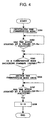
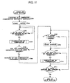
- the commutation control circuit 12 When the power switch of the printer is turned on and thus the control circuit 10 is activated, the commutation control circuit 12 first starts a main routine shown in Fig. 3. In a first step S101 in the main routine, setting of the commutation reference point is performed, wherein the details of this step are shown in Fig. 4. In this step, the commutation control circuit 12 performs an initial pulling-in operation to determine the commutation reference point. That is, first, in step S201, the commutation mode indicating a phase to be excited in the motor 1 is initialized to a predetermined value.
- a commutation signal for exciting the phase specified by the initialized commutation mode is generated and output to the respective transistors in the inverter 11 thereby controlling the respective transistors such that the specified phase is excited and thus performing a first-time pulling-in operation upon the rotor.
- step S202 it is determined whether the rotor has stopped. If the rotor has stopped, the routine goes to step S203. In step S203, it is determined whether a commutation mode switching command has been issued from an upper-level device. If no commutation mode switching command is detected, the routine waits in step S203 until a commutation mode switching command is received. If a commutation mode switching command has been issued, the routine goes to step S204, and the commutation mode is switched in a similar manner as is performed in the conventional commutation control operation. As a result, second-time pulling-in of the rotor is performed by exciting another phase of the motor as specified by the new commutation mode.
- step S205 it is determined whether the rotor has stopped.
- the routine goes to step S206.
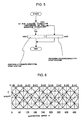
- Fig. 6 illustrates the torque of the respective excited phases varying with the change in the position of the rotor of the motor 1. For example, when the rotor is at a position at which the electrical angle becomes equal to 180°, if the initial value of the commutation mode is set such that a current flows from the phase-B to the phase-C, the rotor is rotated in a direction toward greater angles in Fig. 6 until reaching a position of 270°.
- the commutation mode is switched such that a current flows from the phase-B to the phase-A, the rotor is further rotated toward a position of 330°.
- the rotor does not move in particular cases.
- excitation is performed when the rotor is at rest at a position shifted by an electrical angle of 180° from a first-time pulled-in position.
- the rotor receives torques in both directions, and the magnitudes of the torques are equal in the right and left directions.
- the torques are balanced and the rotor does not move.
- first-time excitation cannot move the rotor which is at rest at the position of 90°
- second-time excitation is performed such that a current flows from the phase-B to the phase-A
- the rotor is pulled into a position of 330°. That is, the rotor receives a torque in a direction toward smaller angles in Fig. 6 and thus is pulled into the position of 330°.
- the position of 90° is equivalent to a position of 450°.
- this commutation reference point is employed as a count reference point, and if the encoder pulse edges are counted with reference to this count reference point, and commutation is performed each time the count value becomes equal to an integral multiple of the predetermined number of encoder pulse edges per commutation interval, commutation is correctly performed whenever the rotor comes to a position at which commutation should be performed.
- the rotor does not move when first-time excitation is performed such that a current flows from the phase-B to the phase-C
- the rotor receives a torque in the direction toward greater angles in Fig. 6, and thus the rotor is rotated until it is pulled into a position of 330°.
- the first-time excitation and the second-time excitation should be different in phase by a magnitude not equal to either 180° or an integral multiple of 180° in electrical angle. More specifically, in the case of a 3-phase motor, the difference in phase may be 60°, 120°, 240°, or 270°.
- step S102 a motor start command is received from the higher-level device
- the routine goes to step S103 to perform a start routine the details of which are shown in Fig. 5.
- step S301 in the start routine, the rotation direction designated by the higher-level device is detected. If the rotation is designated to be in the forward direction, a forward-direction start routine is performed in which the excitation phase is switched in the forward direction (step S302).
- a reverse-direction start routine is performed in which the excitation phase is switched in the reverse direction (step S303). Thereafter, the routine returns to the main routine shown in Fig. 3 and goes to step S104.
- the start routine in step S103 if the motor 1 rotates, the rotational force thereof is transmitted to the carriage 21 via the pulley 22b, and the carriage 21 is moved. As the carriage 21 moves, the position detector 15 disposed on the carriage 21 outputs two types of encoder pulse signals of which phases are different from each other.
- step S104 If an edge of a pulse signal output from the position detector 15 is detected in step S104, the routine goes to step S105 to perform a commutation control routine the details of which are shown in Fig. 7.
- the routine it is first determined, from the two pulse signals, whether the motor 1 is rotating in the forward or reverse direction (step S401). In the case where the rotation is in the forward direction, the routine goes from S401 to S402.
- step S402 the commutation constant T, which has been set in advance and stored in a predetermined storage area, is added to the cumulative value S. Thereafter, the routine goes to step S403, and it is determined whether the cumulative value S is equal to or greater than 1. If the cumulative value S is smaller than 1, the commutation control routine is ended.
- step S403 In the case where it is determined in step S403 that the cumulative value S is equal to or greater than 1, the routine goes to step S404, and the commutation mode is switched with correct timing in the forward direction. Thereafter, in step S405, the cumulative value S is decremented by "1", and the commutation control routine is ended.
- step S401 determines whether the motor 1 is rotating in the reverse direction. If it is determined in step S401 that the motor 1 is rotating in the reverse direction, the routine goes from step S401 to step S406 and the commutation constant T is subtracted from the cumulative value S. Thereafter, in step S407, it is determined whether the cumulative value S is equal to or smaller than "0". If the cumulative value S is greater than "0", the commutation control routine is ended.
- step S407 If it is determined in step S407 that the cumulative value S is equal to or smaller than "0”, the routine goes to step S408, and the commutation mode is switched with correct timing in the reverse direction. Thereafter, in step S409, the cumulative value S is incremented by "1", and the commutation control routine is ended.
- step S106 it is determined whether a main routine end command has been issued from the higher-level device as a result of, for example, turning-off of the power switch of the printer. If the main routine end command has been issued, the main routine shown in Fig. 3 is ended. However, if the main routine end command has not been issued, the routine returns to step S102.
- steps S102 ⁇ S104 ⁇ S105 ⁇ S106 are performed repeatedly.
- the commutation constant T is added to or subtracted from the cumulative value S depending upon the actual rotation direction, and commutation is performed each time the cumulative value S becomes equal to or greater than "1" as a result of addition or becomes equal to or smaller than "0" as a result of subtraction.
- steps S102 ⁇ S104 ⁇ S106 in the main routine shown in Fig. 3 are performed repeatedly.
- the routine goes from step S102 to step S103, and the commutation control operation is performed in the above-described manner.
- excitation is performed twice such that the pulled-in positions of the first-time and second-time excitation become different in electrical angle by a magnitude not equal to either 180° or an integral multiple of 180°. This ensures that the rotor is moved to a pulled-in position regardless of the position at which the rotor is rest before being pulled in. Thus, it is ensured that the cumulative value S is set to "0" precisely at the commutation reference point.
- the commutation constant T is calculated from the amount of rotation of the motor per encoder pulse (or the interval between two successive encoder pulse edges), and the commutation constant T is added to or subtracted from the cumulative value S depending upon the rotation direction each time an edge of any of the pulse signals is detected as the motor 1 rotates.
- the commutation constant T is added to the cumulative value S, each time the cumulative value S becomes equal to or greater than "1" as a result of addition, commutation is performed and "1" is subtracted from the cumulative value S.
- the second embodiment is similar to the first embodiment described above except that the driver circuit 10 additionally includes a zero-crossing detection circuit 13 serving as counter electromotive force detection means and that the commutation control circuit 12 operates differently.
- the driver circuit 10 additionally includes a zero-crossing detection circuit 13 serving as counter electromotive force detection means and that the commutation control circuit 12 operates differently.
- similar parts to those in the first embodiment are denoted by similar reference numerals, and they are not described in further detail herein.
- the zero-crossing detection circuit 13 formed of a comparator or the like, monitors a counter electromotive voltage in one of phases of the motor 1. If the zero-crossing detection circuit 13 detects a mid-point voltage of the counter electromotive voltage, that is, if it detects a zero-crossing point, the zero-crossing detection circuit 13 discriminates the polarity of the counter electromotive voltage immediately before the zero-crossing point. If that polarity is positive, the zero-crossing detection circuit 13 outputs a high-level signal to the commutation control circuit 12, while a low-level signal is output if the polarity is negative.
- the commutation control circuit 12 switches the commutation mode in accordance with the cumulative value S in a similar manner as in the first embodiment.
- the commutation control circuit 12 When the rotation speed of the motor 1 has become high enough to generate a commutation timing on the basis of the zero-crossing of the counter electromotive voltage, the commutation control circuit 12 generates a commutation timing on the basis of detection of zero-crossing and resets the commutation reference point on the basis of the commutation timing.
- the commutation control circuit 12 when the power switch of the printer is turned on and thus the control circuit 10 is activated, the commutation control circuit 12 first starts the main routine shown in Fig. 3 as in the first embodiment.
- a first step S101 in the main routine as in the first embodiment, the commutation reference point setting routine, the details of which are shown in Fig. 4, is performed.
- the motor 1 rotates and the rotational force thereof is transmitted to the carriage 21 via the pulley 22b, and thus the carriage 21 is moved.
- the position detector 15 disposed on the carriage 21 outputs two types of encoder pulse signals of which phases are different from each other.
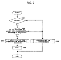
- step S104 If an edge of a pulse signal output from the position detector 15 is detected in step S104, the routine goes to step S105 to perform a commutation control routine the details of which are shown in Fig. 9.
- FRS is set to "0".
- step S502 it is determined whether resetting of the commutation reference point is possible, that is, it is determined whether the rotation speed of the motor 1 is within a range which allows a commutation timing to be generated in accordance with a counter electromotive voltage.
- the determination may be performed, for example, on the basis of the number of encoder pulses per unit time.
- the routine jumps from step S502 to step S505, and the commutation control routine shown in Fig. 7 is performed.
- step S402 the predetermined commutation constant T is added to the cumulative value S each time an edge of any of the pulse signals is detected.
- step S403 the routine goes from step S403 to step S404, and the commutation mode is switched. Thereafter, in step S405, "1" is subtracted from the cumulative value S.
- step S502 When the rotation speed of the motor 1 has increased to a level high enough to detect a counter electromotive voltage, the routine goes from step S502 to S503 to perform a commutation reference point resetting routine the details of which are shown in Fig. 10.
- a count value CT is set to one-half the number of encoder pulse edges output from the position detector 15 during one commutation interval. More specifically, for example, the count value CT is set to an integer given by round(M/2), that is, an integer obtained by rounding M/2 where M is the number of encoder pulse edges per commutation interval detected when the commutation constant T is calculated.
- step S603 if an edge of any of the pulse signals output from the position detector 15 is detected, the routine goes from step S603 to step S604, and the count value CT is decremented by "1". Thereafter, in step S605, it is determined whether the count value CT is equal to "0". If the count value CT is not equal to "0", the routine returns from step S605 to S603 and waits until the next edge of any of pulse signals is detected. If the count value CT becomes equal to 0, it is determined that a timing of commutation has been reached, and the routine goes to step S606.
- step S606 it is determined whether the rotation is in the forward direction. If the rotation is in the forward direction, the routine goes to step S607, and the commutation mode is switched in the forward direction. Thereafter, the routine goes to step S609. However, if it is determined in step S606 that the rotation is in the reverse direction, the routine goes from step S606 to step S608, and the commutation mode is switched in the reverse direction.
- step S609 it is determined that the commutation reference point has been correctly reset, and the cumulative value S is reset to "0". Thus, the commutation reference point resetting routine is completed. Thereafter, the routine returns from Fig. 10 to Fig. 9. In Fig. 9, the routine goes from step S503 to step S504, and the commutation reference point reset flag FRS is set to "1".
- step S104 in Fig. 3 the routine goes from step S501 in Fig. 9 to step S505, and the commutation control routine shown in Fig. 7 is performed in a similar manner to the first embodiment described above. That is, the commutation mode is switched in accordance with the cumulative value S which is updated in response to rotation.
- the third embodiment is similar to the first embodiment except that the commutation control circuit 12 operates differently, and thus, similar parts to those in the first embodiment are denoted by similar reference numerals, and they are not described in further detail herein.
- the third embodiment there are two commutation reference points, one of which is used when the carriage 21 is moved in the right direction, and the other one of which is used when the carriage 21 is moved in the left direction.
- the two commutation reference points are set when the carriage 21 is at a predetermined position for setting the communication reference points.
- the position for setting the communication reference points is selected near the center of the belt 23, i.e., the position of the belt in the middle between the pulley 22a and the pulley 22b.
- step S701 a tentative commutation reference point is set for use in moving the carriage 21 to the position for setting the actual commutation reference points.
- step S702 the setting is performed in a similar manner to the commutation reference point setting routine described above with reference to Fig. 4.
- step S702 the motor 1 is operated so as to move the carriage 21 toward the position where the actual commutation reference points are set.
- step S703 If, as a result of the movement of the carriage 21 driven by the motor 1, an edge of a pulse signal output from the position detector 15 is detected in step S703, the routine goes to step S704 to perform the commutation control routine the details of which are shown in Fig. 7, In step S705, it is determined whether the carriage 21 has reached the position where the actual commutation reference points are set. If not, the routine returns to step S703, and steps S703 to S705 are performed repeatedly until the carriage 21 reaches the position where the actual commutation reference points are set. If it is determined in step S705 that the carriage 21 has reached the position where the actual commutation reference points are set, the routine goes to step S706.
- step S704 the value of the commutation mode at the end of step S704, that is, at the end of the commutation control routine shown in Fig. 7, is maintained, and thus the rotor of the motor 1 stops at the pulled-in position defined in that commutation mode.
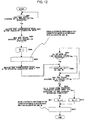
- step S706 a commutation reference point setting routine is performed as shown in Fig. 12.
- step S801 in the commutation reference point setting routine shown in Fig. 12 it is determined whether the rotor of the motor 1 has stopped at the pulled-in position. If it is determined in step S801 that the rotor has stopped at the pulled-in position, the routine goes to step S802, and the commutation mode is forcedly switched once in the forward direction (in a direction which causes the carriage 21 to move to the right, in this specific example). Thereafter, the routine goes to step S803. In step S803, it is determined whether the rotor of the motor 1 has stopped at the corresponding pulled-in position. If the rotor has stopped at the pulled-in position, the routine goes to step S804.
- step S803 is repeated until the rotor has stopped at the pulled-in position.
- step S804 the pulled-in position at which the rotor is currently at rest is employed as the commutation reference point for use when the carriage 21 is moved in the right direction, and the cumulative value SR for use in moving the carriage 21 in the right direction is set to 1. Furthermore, the cumulative value SL for use in moving the carriage 21 in the left direction is also set to 1.
- the routine goes to step S805, and automatic switching of the commutation mode in accordance with the cumulative values SR and SL is disabled. The automatic switching operation of the commutation mode will be described later with reference to Fig. 13.
- step S806 the commutation mode is forcedly switched once in an opposite direction (in a direction which causes the carriage 21 to be moved to the left, in this specific example), and the routine goes to step S808.
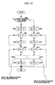
- step S808 counting associated with the cumulative values SR and SL is performed as shown in Fig. 13.
- a first step S901 in the counting routine shown in Fig. 13 it is determined, from the two pulse signals, whether the motor 1 is rotating in the forward or reverse direction that is, it is determined whether the carriage 21 is moving in the right or left direction.
- the predetermined commutation constant T is added to the cumulative values SR and SL, respectively (step S902).
- the commutation constant T is equal to 1/M where M is the number of encoder pulse edges per commutation interval.
- step S903 it is determined whether the cumulative value SL is equal to or greater than "1". If SL is smaller than "1", the routine goes to step S905. On the other hand, if SL is equal to or greater than "1”, the routine goes to step S904, and "1" is subtracted from SL. Thereafter, the routine goes to step S905. In step S905, it is determined whether the cumulative value SR is equal to or greater than "1". If SR is smaller than "1", the counting routine shown in Fig. 13 is ended. However, if SR is equal to or greater than "1”, it is determined that a timing of commutation has been reached, and the routine goes to step S906.
- step S906 the commutation mode is switched in the forward direction.
- step S808 the counting routine shown in Fig. 13
- step S805 the automatic switching of the commutation mode in accordance with the value of SR or SL has been disabled in step S805
- step S907 "1" is subtracted from the value of SR.
- the counting routine shown in Fig. 13 is completed.
- step S901 In the case where it is determined in step S901 that the motor 1 is rotating in the reverse direction, the routine goes to step S908, and the commutation constant T is subtracted from the respective cumulative values SR and SL. Thereafter, in step S909, it is determined whether the cumulative value SR is equal to or smaller than "0". If the value of SR is greater than "0", the routine goes to step S911. However, if the value of SR is equal to or smaller than "0”, the routine goes to step S910, and "1" is added to the value of SR. Thereafter, the routine goes to step S911. In step S911, it is determined whether the cumulative value SL is equal to or smaller than "0".
- step S912 If the value of SL is greater than "0”, the counting routine shown in Fig. 13 is ended. However, if the value of SL is equal to or smaller than "0", it is determined that a timing of commutation has been reached, and the routine goes to step S912. In a normal situation, in this step S912, the commutation mode is switched in the reverse direction. However, in this specific case, because the automatic switching of the commutation mode in accordance with the value of SR or SL has been disabled as described above, the routine goes to step S913 without executing the switching of the commutation mode in step S912. In step S913, "1" is added to the value of SL, and the counting routine shown in Fig. 13 is ended.
- step S809 the routine goes to step S809 to determine whether the rotor of the motor 1 has stopped at the pulled-in position. If the rotor has not stopped, the routine goes to step S807, and steps S807 to S809 are performed repeatedly until the rotor has stopped at the pulled-in position.
- the counting of SR and SL is performed such that each time an edge of any of the pulse signals is detected, the commutation constant T is added to or subtracted from the cumulative value SR or SL, depending upon the rotation direction, and each time the value of SR or SL becomes equal to or greater than "1" or equal to or smaller than "0", "1" is subtracted from or added to the cumulative value SR or SL, depending upon the rotation direction. Note that, in the above process, the commutation mode is not switched regardless of the values of SR and SL.
- step S809 If it is determined in step S809 that the rotor has stopped at the pulled-in position, this pulled-in position is employed as the commutation reference point for use in moving the carriage 21 in the left direction, and the cumulative value SL is reset.
- the cumulative value SL is reset to a different value depending upon the rotation direction specified by the higher-level device after completion of the commutation reference point setting routine.
- the reverse direction in this specific example, the reverse direction is defined as the direction which causes the carriage 21 to be moved in the left direction
- step S706 After completion of the commutation reference point setting routine shown in Fig. 12, that is, step S706 shown in Fig. 11, the routine goes to step S707 shown in Fig. 11 to determine whether a start command to start the motor 1 has been issued from the higher-level device. If it is determined in step S707 that a start command has been issued, the routine goes to step S708, and the start routine shown in Fig. 5 is performed in a similar manner as in the first embodiment. Thereafter, the routine goes to step S709. In step S709, if an edge of a pulse signal output from the position detector is detected as a result of movement of the carriage 21, the routine goes to step S710, and a commutation control routine is performed as shown in Fig. 13.
- step S710 the routine goes to step S711 to determine whether a main routine end command has been issued from the higher-level device as a result of, for example, turning-off of the power switch of the printer. If the main routine end command has been issued, the main routine shown in Fig. 11 is ended. However, if the main routine end command has not been issued, the routine returns to step S707.
- step S710 is executed such that the commutation constant T is added to or subtracted from the cumulative value SR or SL, depending upon the rotation direction, and, in the case where the carriage 21 is moving in the right direction, each time the value of SR becomes equal to or greater than "1", the commutation mode is switched, while in the case where the carriage 21 is moving in the left direction, each time the value of SL becomes equal to or smaller than "0", the commutation mode is switched.
- steps S707 ⁇ S709 ⁇ S711 in the main routine shown in Fig. 11 are performed repeatedly.
- the routine goes from step S707 to step S708, and the commutation control operation is performed in the above-described manner.
- the absolute position of the rotor corresponding to a certain absolute position of the carriage 21 varies depending upon the rotation direction.
- the commutation reference point is separately set for use in rotation in the forward direction and for use in rotation in the reverse direction, and the commutation timing is generated on the basis of the cumulative value SR when the rotation is in the forward direction and on the basis of the cumulative value SL when the rotation is in the reverse direction thereby eliminating an error which would otherwise occur due to the difference in the amount of expansion of the belt and thus preventing the commutation timing from shifting from the correct timing depending upon the direction of rotation of the motor 1 thus ensuring that commutation is performed with correct timings.
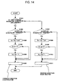
- step S708 shown in Fig. 11 is performed in such a manner as shown in Fig. 14.
- a first step S1001 in the start routine shown in Fig. 14 it is determined which rotation direction is specified by the higher-level device. If the forward rotation direction is specified, the routine goes to step S1002.
- step S1002 it is determined whether the specified rotation direction is opposite to an immediately previous rotation direction. If the specified rotation direction is the same as the immediately previous rotation direction, that is, if the rotation should be still in the forward direction as in the immediately previous operation, the routine goes from step S1002 to step S1006 to perform a forward-direction start routine.
- the routine goes from step S1002 to step S1003, and the reference point error ⁇ S is added to the cumulative value SR. Thereafter, the routine goes to step S1004 to determine whether the cumulative value SR is equal to or greater than "1". If the cumulative value SR is smaller than "1", the routine goes to step S1006. However, if the cumulative value SR is equal to or greater than "1", the routine goes to step S1005, and "1" is subtracted from the value of SR. Thereafter, the routine goes to step S1006, and the forward-direction start routine is performed. Thereafter, the start routine of Fig. 14 is ended.
- step S1007 it is determined whether the specified rotational direction is opposite to the immediately previous rotation direction. If the specified rotation direction is the same as the immediately previous rotation direction, that is, if the rotation should be still in the reverse direction as in the immediately previous operation, the routine goes from step S1007 to step S1011 to perform a reverse-direction start routine. On the other hand, if the specified rotation direction is opposite to the immediately previous direction, that is, if the rotation direction should be changed from the forward direction to the reverse direction, the routine goes from step S1007 to step S1008, and the reference point error ⁇ S is subtracted from the value of SR.
- step S1009 it is determined whether the cumulative value SR is equal to or smaller than "0". If the cumulative value SR is greater than "0", the routine goes to step S1011. However, if the cumulative value SR is equal to or smaller than "0", the routine goes to step S1010, and "1" is added to the value of SR. Thereafter, the routine goes to step S1011. In step S1011, the reverse-direction start routine is performed. After the completion of the reverse-direction start routine in step S1011, the start routine shown in Fig. 14 is ended.
- the following commutation control can be performed simply by replacing the cumulative value S with SR in the commutation control routine shown in Fig. 7. That is, each time the rotation direction is switched, the cumulative value SR is corrected by the reference point error ⁇ S, and thus the commutation control routine can be performed in a simplified manner.
- the fourth embodiment is similar to the second embodiment described above except that the commutation control circuit 12 operates differently, and thus similar parts to those in the second embodiment are denoted by similar reference numerals, and they are not described in further detail herein.
- two commutation reference points are used, one of which is used when the carriage 21 is moved in the right direction, and the other one of which is used when the carriage 21 is moved in the left direction, and the two commutation reference points are reset on the basis of zero-crossing of a counter electromotive voltage which is generated in a non-exciting phase of the stator coils of the motor 1 and which is detected by the zero-crossing detection circuit 13.
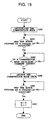
- step S101 a commutation reference point setting routine shown in Fig. 15 is performed.
- pulling-in of the rotor is performed twice in steps S201 to S205. If it is determined in step S205 that the rotor has stopped at a pulled-in position, the routine goes from step S205 to step S207.
- step S207 the cumulative value SR used in the commutation control when the carriage 21 is moved in the right direction is set to "0", and the cumulative value SL used in the commutation control when the carriage 21 is moved in the left direction is set to "1", and thus the commutation reference point is set.
- the routine goes to step 102.
- step S102 if a start command to start the motor 1 is issued by the higher-level device, the routine goes to step S103, and the start routine shown in Fig. 5 is performed as in the first embodiment. If an edge of a pulse signal, which is output from the position detector 15 in response to the movement of the carriage 21, is detected (step S104), the routine goes to step S105, and a commutation control routine shown in Fig. 16 is performed.
- FR has a value of "1" when resetting of the commutation reference point used when the carriage 21 is moved in the right direction has been completed, while FR has a value of "0" if the resetting is not completed.
- FL has a value of "1” when resetting of the commutation reference point used when the carriage 21 is moved in the left direction has been completed, while FL has a value of "0” if the resetting is not completed.
- both FR and FL are set to "0".
- step S1101 it is determined whether the rotation of the motor 1 is presently in the forward direction. If the rotation is in the forward direction (which is defined in this specific embodiment as the direction causing the carriage 21 to move in the right direction), the routine goes to step S1102, however, if the rotation is in the reverse direction (which is defined in this specific embodiment as the direction causing the carriage 21 to move in the left direction), the routine goes to step S1106. In the case where the rotation is in the forward direction, it is determined in step S1102 whether the value of FR is equal to "0". If the value of FR is equal to "0", that is, if the resetting of the right-direction commutation reference point is not completed, the routine goes to step S1103.
- step S1103 it is determined whether the resetting of the commutation reference point is possible in a similar manner as is described in the second embodiment.
- the routine goes from step S1103 to step S1110, and the commutation control routine shown in Fig. 13 is performed in a similar manner as is described in the third embodiment.
- the commutation constant T is added to or subtracted from the cumulative value SR or SL, depending upon the rotation direction, and, in the case where the carriage 21 is moving in the right direction, each time the value of SR becomes equal to or greater than "1", the commutation mode is switched, while in the case where the carriage 21 is moving in the left direction, each time the value of SL becomes equal to or smaller than "0", the commutation mode is switched.
- the routine goes from step S1103 to S1104 to perform the commutation reference point resetting routine shown in Fig. 10 in a similar manner as described in the second embodiment.
- the routine goes from step S1104 in Fig. 16 to step S1105, and the right-direction cumulative value SR is reset to "0", and the value of FR is set to "1" to indicate that the resetting of the right-direction commutation reference point has been completed.
- step S1101 In the case where it is determined in step S1101 that the rotation is in the reverse direction, the routine goes to step S1106 to determine whether the value of FL is equal to "0". If the value of FL is equal to "0", that is, if the resetting of the left-direction commutation reference point has not been completed, the routine goes to step S1107. In step S1107, it is determined whether the resetting of the commutation reference point is possible in a similar manner as in step S1103. In the case where the resetting of the commutation reference point on the basis of the counter electromotive voltage is not possible, the routine goes from step S1107 to S1110, and the commutation control routine shown in Fig. 13 is performed.
- step S1107 the routine goes from step S1107 to step S1108, and the resetting of the commutation reference point shown in Fig. 10 is performed in a similar manner to step S1104. Thereafter, the routine goes to step S1109, and the left-direction cumulative value SL is reset to "1", and furthermore the value of FL is set to "1" to indicate that the resetting of the left-direction commutation reference point has been completed.
- step S104 and S105 each time an edge of an encoder pulse is detected, the routine goes from step S1102 or step S1106 in Fig. 16 to step S1110, and the commutation control routine shown in Fig. 13 is performed as in the third embodiment described above.
- the commutation reference point is separately provided for use with rotation in the forward direction and for use with rotation in the reverse direction, and the respective commutation reference points are reset in synchronization with the commutation timing generated on the basis of the counter electromotive voltage.
- the timing of performing commutation of the motor used to move the carriage is detected on the basis of the pulse signals output from the encoder (position detector) disposed on the carriage of the printer; the present invention is not limited to such a detection technique, but other position detection techniques may also be employed as long as the position detector can output a pulse signal corresponding to the amount of movement of the object to be driven.
- a sensor such as a potentiometer may be used to detect the position of the object to be driven.
- a pulse generator is provided such that when the position information output from the potentiometer indicates that the object being driven has moved a predetermined distance, the pulse generator outputs one pulse, and controlling is performed in a similar manner to one of the embodiments described above on the basis of the pulse signal output from the pulse generator thereby achieving advantages similar to those obtained in the embodiments described above.
- commutation is controlled on the basis of the detection signal output from the position detector 15, not only the commutation but also the speed or the phase may also be controlled on the basis of the detection signal output from the position detector 15.
- the present invention is applied to a DC brushless motor in the embodiments described above, the invention is not limited to DC brushless motors.
- the invention may also be applied to other types of motors such as a stepper motor.
- a linear encoder is employed as an encoder in the embodiments described above, other types of encoders such as an optical encoder or a magnetic encoder may also be employed.
- the invention is applied to a 3-phase brushless motor in the embodiments described above, the invention may also be applied to other types of brushless motors such as a single-phase brushless motor, a 2-phase brushless motor, a 4-phase brushless motor, or brushless motors having a greater number of phases.
- the zero-crossing detection circuit 13 detects counter electromotive force of one of phases and detects zero-crossing on the basis of the detected counter electromotive force, the zero-crossing may be detected for all phases.
- detection for one phase is more advantageous in that the zero-crossing can be detected by simpler processing with a simpler construction.
- the resetting of the commutation reference point is performed when the rotation speed of the motor 1 becomes high enough to detect zero-crossings of the counter electromotive voltage. This may also be achieved, for example, as follows. After the driver circuit 10 is activated, the motor 1 is rotated to perform the resetting of the commutation reference point. After completion of the resetting of the commutation reference point, driving control is started in response to a command signal output from the higher-level device. The resetting of the commutation reference point may be performed not only when the driver circuit 10 is started, but also in predetermined intervals of time after starting to drive the motor 1 so as to eliminate the influence of a change in temperature caused by the driving of the motor 1.
- the resetting may be performed when a predetermined period of time has elapsed and thus the change in temperature has reached an equilibrium state.
- the resetting of the commutation reference point may also be performed each time the rotation speed of the motor 1 becomes high enough to detect the commutation timing after the motor 1 is started.
- a commutation reference point error ⁇ S may be measured and stored in a storage area such as a ROM in advance, and, after setting the commutation reference point for use in driving in one rotation direction, the cumulative value S obtained with reference to that commutation reference point may be corrected on the basis of the commutation reference point error ⁇ S each time the rotation direction is switched.
- a position detector that outputs two types of pulse signal whenever the object driven by the motor is moved.
- the two pulse signals are phase-shifted with respect to one another and allow detection of the rotation direction of the rotor.
- Preferred embodiments of the present invention use one or both of these pulse signals to obtain a measure representing the rotor position of the motor. To this end either the number of pulses or the number of pulse edges may be counted.
- pulse number and similar terms are intended to cover each of the following four possibilities: (1) the number of pulses as represented by the number of either the leading or the trailing edges detected in one of the two pulse signals, (2) the number of pulses as represented by the number of either the leading or the trailing edges detected in both pulse signals, (3) the number of pulses as represented by the number of the leading and the trailing edges detected in one of the two pulse signals, and (4) the number of pulses as represented by the number of the leading and the trailing edges detected in both pulse signals.
- the foregoing description explains embodiments that use alternative (4) but each of the other three alternatives may be used instead for each of these embodiments.
Landscapes
- Engineering & Computer Science (AREA)
- Power Engineering (AREA)
- Control Of Motors That Do Not Use Commutators (AREA)
- Control Of Ac Motors In General (AREA)
Abstract
Description
- Fig. 1
- is a schematic diagram of a driver circuit for driving a brushless motor, according to a first embodiment of the present invention.
- Fig. 2
- is a schematic diagram of a system in which a carriage is driven by a sensorless motor.
- Fig. 3
- is a flow chart illustrating an example of a main routine according to a first, second, and fourth embodiment.
- Fig. 4
- is a flow chart illustrating an example of a commutation reference point setting routine according to the first, second, and fourth embodiments.
- Fig. 5
- is a flow chart illustrating an example of a start routine.
- Fig. 6
- is a diagram illustrating excited phases and torque varying with the change in the position of a rotor.
- Fig. 7
- is a flow chart illustrating an example of a commutation control routine according to the first and a second embodiment.
- Fig. 8
- is a diagram illustrating a configuration of a sensorless motor driver circuit according to the second and fourth embodiments.
- Fig. 9
- is a flow chart illustrating an example of a commutation control routine according to the second embodiment.
- Fig. 10
- is a flow chart illustrating an example of a commutation reference point resetting routine according to the second and fourth embodiments.
- Fig. 11
- is a flow chart illustrating an example of a main routine according to a third embodiment.
- Fig. 12
- is a flow chart illustrating an example of a commutation reference point setting routine according to the third embodiment.
- Fig. 13
- is a flow chart illustrating an example of a commutation control routine according to the third and fourth embodiments.
- Fig. 14
- is a flow chart illustrating an example of a start routine according to the third and fourth embodiments.
- Fig. 15
- is a flow chart illustrating an example of a commutation reference point setting routine according to the fourth embodiment.
- Fig. 16
- is a flow chart illustrating an example of a commutation control routine according to the fourth embodiment.
Claims (11)
- A sensorless motor driving apparatus comprising:wherein said commutation reference point setting means is adapted toa position detector for outputting a pulse signal in response to movement of an object driven by a sensorless motor;commutation control means which counts the number of pulses output from said position detector and controls the commutation of said motor depending upon the counted value; andcommutation reference point setting means for setting a commutation reference point employed as a reference point in the counting of said pulses;perform, when said motor is started for the first time, phase excitation twice such that two different phases are excited and that a pulled-in position resulting from the first-time excitation and that resulting from the second-time excitation become different in electrical angle from each other by a magnitude not equal to either 180° or an integral multiple of 180°, andset said commutation reference point when the rotor of said motor has stopped after the second-time excitation.
- The apparatus according to Claim 1, wherein said commutation reference point setting means sets said commutation reference point for each rotation direction of said motor, and wherein said commutation control means controls the commutation depending upon the current rotation direction in accordance with the number of pulses as counted starting from the commutation reference point set for the current rotation direction.
- The apparatus according to Claim 2, wherein said commutation reference point setting means detects an offset value indicating the number of pulses corresponding to the difference in position between the commutation reference points set for the respective rotation directions of said motor, and wherein said commutation control means counts the pulses with respect to one of the commutation reference points and corrects the counted value of pulses on the basis of said offset value each time the rotation direction is switched.
- The apparatus according to one of Claims 1 to 3, further comprising:wherein said commutation reference point setting means resets said commutation reference point at a point of time of the commutation timing generated by said commutation timing generating means.counter electromotive force detection means for detecting a counter electromotive force induced in not excited phase of said motor; andcommutation timing generating means for generating a commutation timing in accordance with the counter electromotive force detected by said counter electromotive force detection means,
- The apparatus according to Claim 4, wherein said commutation timing generating means generates a commutation timing in accordance with the counter electromotive force of one of the phases of said motor.
- The apparatus according to Claim 4 or 5, wherein said commutation timing generating means generates a commutation timing for each rotation direction of said motor, and wherein said commutation reference point setting means resets the commutation reference points for the respective rotation directions in accordance with the corresponding commutation timings generated for the respective rotation directions.
- The apparatus according to Claim 6, wherein said commutation reference point setting means detects an offset value indicating the number of pulses corresponding to the difference in position between the commutation reference points reset in accordance with the commutation timings generated for the respective rotation directions by said commutation timing generating means, and said commutation reference point setting means includes storage means for storing said offset value, and wherein said commutation control means counts pulses with respect to one of the reset commutation reference points and corrects the counted value of pulses on the basis of the offset value stored in said storage means each time the rotation direction is switched.
- The apparatus according to one of Claims 4 to 7, wherein when controlling of said motor is started, said commutation control means performs the resetting of a commutation reference point in accordance with a commutation timing generated by said commutation timing generating means.
- The apparatus according to one of Claims 4 to 8, wherein when a predetermined period of time has elapsed since controlling of said motor was started, said commutation control means performs the resetting of a commutation reference point in accordance with a commutation timing generated by said commutation timing generating means.
- The apparatus according to one of Claims 4 to 9, wherein each time a predetermined period of time elapses after controlling of said motor was started, said commutation control means performs the resetting of a commutation reference point in accordance with a commutation timing generated by said commutation timing generating means.
- The apparatus according to one of Claims 4 to 10, wherein each time said motor is started, said commutation control means performs the resetting of a commutation reference point in accordance with a commutation timing generated by said commutation timing generating means.
Applications Claiming Priority (2)
| Application Number | Priority Date | Filing Date | Title |
|---|---|---|---|
| JP2000219465 | 2000-07-19 | ||
| JP2000219465A JP3690250B2 (en) | 2000-07-19 | 2000-07-19 | Sensorless motor drive device |
Publications (2)
| Publication Number | Publication Date |
|---|---|
| EP1174999A2 true EP1174999A2 (en) | 2002-01-23 |
| EP1174999A3 EP1174999A3 (en) | 2002-12-18 |
Family
ID=18714247
Family Applications (1)
| Application Number | Title | Priority Date | Filing Date |
|---|---|---|---|
| EP01117135A Withdrawn EP1174999A3 (en) | 2000-07-19 | 2001-07-13 | Sensorless motor driving apparatus |
Country Status (4)
| Country | Link |
|---|---|
| US (1) | US6483266B2 (en) |
| EP (1) | EP1174999A3 (en) |
| JP (1) | JP3690250B2 (en) |
| CN (1) | CN1193496C (en) |
Cited By (1)
| Publication number | Priority date | Publication date | Assignee | Title |
|---|---|---|---|---|
| EP1460757A1 (en) * | 2003-03-21 | 2004-09-22 | AMI Semiconductor Belgium BVBA | Device and method for detecting rotor speed of a multiple phase motor with bipolar drive |
Families Citing this family (20)
| Publication number | Priority date | Publication date | Assignee | Title |
|---|---|---|---|---|
| JP3690296B2 (en) * | 2001-03-26 | 2005-08-31 | セイコーエプソン株式会社 | Sensorless motor drive device |
| US6901212B2 (en) | 2002-06-13 | 2005-05-31 | Halliburton Energy Services, Inc. | Digital adaptive sensorless commutational drive controller for a brushless DC motor |
| US7514887B2 (en) * | 2003-10-24 | 2009-04-07 | A. O. Smith Corporation | Electrical machine and method of controlling the same |
| JP3985792B2 (en) * | 2004-02-13 | 2007-10-03 | 松下電器産業株式会社 | Electric motor drive device and air conditioner using the same |
| KR101041076B1 (en) * | 2004-12-17 | 2011-06-13 | 삼성전자주식회사 | Starting control method of brushless DC motor |
| CN1326318C (en) * | 2005-06-23 | 2007-07-11 | 南京航空航天大学 | Control method of double-salient-pole electric machine without position sensor |
| FR2896104B1 (en) * | 2006-01-11 | 2009-01-30 | Valeo Equip Electr Moteur | METHOD FOR DETERMINING THE POSITION OF A ROTOR OF A SYNCHRONOUS MACHINE PROVIDED WITH AT LEAST ONE EXCITATION WINDING |
| JP5359021B2 (en) * | 2007-06-28 | 2013-12-04 | セイコーエプソン株式会社 | Electric motor drive control circuit |
| DE102008037543A1 (en) * | 2007-12-28 | 2009-07-02 | DENSO CORPORARTION, Kariya-shi | Engine control device, vehicle fan drive device and engine control method |
| JP5610838B2 (en) * | 2010-05-11 | 2014-10-22 | キヤノン株式会社 | Equipment with motor |
| US8901867B2 (en) | 2011-04-28 | 2014-12-02 | Regal Beloit America, Inc. | Electrical machine, method of controlling an electrical machine, and system including an electrical machine |
| JP5853438B2 (en) * | 2011-06-29 | 2016-02-09 | 株式会社ジェイテクト | Sensorless control device for brushless DC motor |
| CN102332859B (en) * | 2011-09-16 | 2015-06-03 | 天津市亚安科技股份有限公司 | Closed-loop control method and system for stepping motor |
| KR101927246B1 (en) * | 2012-12-12 | 2019-03-12 | 한국전자통신연구원 | Position of motor detecting unit and brushless dc motor system |
| CN103475283B (en) * | 2013-07-10 | 2016-08-17 | 江苏浩峰汽车附件有限公司 | A kind of automobile-used pump class brushless DC motor without sensor localization method |
| US9559623B2 (en) | 2013-08-30 | 2017-01-31 | Regal Beloit America, Inc. | Method of controlling an electrical machine |
| CN204068791U (en) * | 2014-03-25 | 2014-12-31 | 睿能机电有限公司 | A kind of electromagnetic torque pulsation suppression device of brshless DC motor |
| JP6393699B2 (en) | 2016-01-28 | 2018-09-19 | ミネベアミツミ株式会社 | Motor drive control device and motor drive control method thereof |
| CN113258836B (en) * | 2021-04-20 | 2022-09-09 | 山东大学 | Motor control method and system for vehicle cooling fan based on Kalman filter estimation |
| JP7770251B2 (en) * | 2022-05-26 | 2025-11-14 | ミネベアミツミ株式会社 | Motor drive control device, motor unit, and motor drive control method |
Family Cites Families (8)
| Publication number | Priority date | Publication date | Assignee | Title |
|---|---|---|---|---|
| US5245359A (en) * | 1990-07-02 | 1993-09-14 | Canon Kabushiki Kaisha | Recording apparatus with recording head carriage driving motor control |
| DE4407390A1 (en) * | 1994-03-05 | 1995-09-14 | Grundig Ag | Startup and commutation procedures for synchronous machines |
| US5466999A (en) * | 1994-08-15 | 1995-11-14 | Maxtor Corporation | Spindle motor start control process and apparatus |
| US5689165A (en) * | 1996-04-09 | 1997-11-18 | Sundstrand Corporation | Estimator initialization circuit and method for a sensorless switched reluctance machine system |
| US5920175A (en) * | 1996-04-09 | 1999-07-06 | Sundstrand Corporation | Instantaneous position indicating apparatus for a sensorless switched reluctance machine system |
| US5844385A (en) * | 1996-07-10 | 1998-12-01 | Sundstrand Corporation | Absolute angle estimation apparatus for a sensorless switched reluctance machine system |
| US5998946A (en) * | 1997-10-08 | 1999-12-07 | Daewoo Electronics Co., Ltd. | Method and apparatus for controlling a rotation of a sensorless and brushless DC motor |
| WO2000004632A1 (en) * | 1998-07-16 | 2000-01-27 | Seiko Epson Corporation | Method and device for controlling position sensorless motor |
-
2000
- 2000-07-19 JP JP2000219465A patent/JP3690250B2/en not_active Expired - Fee Related
-
2001
- 2001-07-13 EP EP01117135A patent/EP1174999A3/en not_active Withdrawn
- 2001-07-18 CN CNB011248548A patent/CN1193496C/en not_active Expired - Fee Related
- 2001-07-18 US US09/908,433 patent/US6483266B2/en not_active Expired - Lifetime
Cited By (1)
| Publication number | Priority date | Publication date | Assignee | Title |
|---|---|---|---|---|
| EP1460757A1 (en) * | 2003-03-21 | 2004-09-22 | AMI Semiconductor Belgium BVBA | Device and method for detecting rotor speed of a multiple phase motor with bipolar drive |
Also Published As
| Publication number | Publication date |
|---|---|
| CN1193496C (en) | 2005-03-16 |
| JP3690250B2 (en) | 2005-08-31 |
| CN1334642A (en) | 2002-02-06 |
| EP1174999A3 (en) | 2002-12-18 |
| US6483266B2 (en) | 2002-11-19 |
| JP2002044986A (en) | 2002-02-08 |
| US20020050800A1 (en) | 2002-05-02 |
Similar Documents
| Publication | Publication Date | Title |
|---|---|---|
| EP1174999A2 (en) | Sensorless motor driving apparatus | |
| EP1246355A2 (en) | Apparatus for driving sensorless motor | |
| US6791293B2 (en) | Sensorless control device for synchronous electric motor | |
| US6683427B2 (en) | Device for controlling an electronically commutated motor | |
| US7205738B2 (en) | Method and apparatus for time-based dc motor commutation | |
| EP1284044A1 (en) | Controlling a brushless dc motor | |
| JP2016158413A (en) | Motor control device | |
| KR20050043630A (en) | Sensorless brushless motor | |
| US7622882B2 (en) | Position detection device for permanent magnetic machines | |
| JP2009124864A (en) | Motor drive device | |
| JP3698024B2 (en) | Motor drive device | |
| KR100713776B1 (en) | Method and apparatus for detecting excitation position of SM through comparison of detection current | |
| KR960036278A (en) | Driving device of brushless DC motor | |
| CN107340472A (en) | A kind of detection means and method of stepper motor motion state | |
| KR20170071260A (en) | Method and system for detecting a position of low speed section in sensorless motor | |
| JP3888278B2 (en) | Motor control device | |
| JPH027280B2 (en) | ||
| CN110476347B (en) | Motor control device and motor control method | |
| JPS62290380A (en) | Absolute encoder | |
| JP2022002423A (en) | Motor device | |
| JPWO2020059759A1 (en) | Motor drive controller, motor unit, and actuator | |
| JPH10146083A (en) | Control device for switched reluctance motor | |
| JPH04368489A (en) | Rotor position detecting method for brushless motor | |
| JPS63287389A (en) | Motor driving circuit | |
| JPS6217960B2 (en) |
Legal Events
| Date | Code | Title | Description |
|---|---|---|---|
| PUAI | Public reference made under article 153(3) epc to a published international application that has entered the european phase |
Free format text: ORIGINAL CODE: 0009012 |
|
| AK | Designated contracting states |
Kind code of ref document: A2 Designated state(s): AT BE CH CY DE DK ES FI FR GB GR IE IT LI LU MC NL PT SE TR |
|
| AX | Request for extension of the european patent |
Free format text: AL;LT;LV;MK;RO;SI |
|
| PUAL | Search report despatched |
Free format text: ORIGINAL CODE: 0009013 |
|
| AK | Designated contracting states |
Kind code of ref document: A3 Designated state(s): AT BE CH CY DE DK ES FI FR GB GR IE IT LI LU MC NL PT SE TR |
|
| AX | Request for extension of the european patent |
Free format text: AL;LT;LV;MK;RO;SI |
|
| RIC1 | Information provided on ipc code assigned before grant |
Free format text: 7H 02P 6/14 A, 7H 02P 6/18 B, 7H 02P 8/14 B, 7H 02P 6/20 B |
|
| 17P | Request for examination filed |
Effective date: 20021204 |
|
| AKX | Designation fees paid |
Designated state(s): DE FR GB |
|
| 17Q | First examination report despatched |
Effective date: 20100218 |
|
| STAA | Information on the status of an ep patent application or granted ep patent |
Free format text: STATUS: THE APPLICATION IS DEEMED TO BE WITHDRAWN |
|
| 18D | Application deemed to be withdrawn |
Effective date: 20100629 |