EP1174959A2 - EMI gasket for connector assemblies - Google Patents
EMI gasket for connector assemblies Download PDFInfo
- Publication number
- EP1174959A2 EP1174959A2 EP01116581A EP01116581A EP1174959A2 EP 1174959 A2 EP1174959 A2 EP 1174959A2 EP 01116581 A EP01116581 A EP 01116581A EP 01116581 A EP01116581 A EP 01116581A EP 1174959 A2 EP1174959 A2 EP 1174959A2
- Authority
- EP
- European Patent Office
- Prior art keywords
- gasket
- plug portion
- major sides
- sides
- connector
- Prior art date
- Legal status (The legal status is an assumption and is not a legal conclusion. Google has not performed a legal analysis and makes no representation as to the accuracy of the status listed.)
- Granted
Links
- 230000000712 assembly Effects 0.000 title description 8
- 238000000429 assembly Methods 0.000 title description 8
- 230000013011 mating Effects 0.000 claims abstract description 32
- 239000007769 metal material Substances 0.000 claims description 4
- 230000037431 insertion Effects 0.000 claims description 2
- 238000003780 insertion Methods 0.000 claims description 2
- 230000000295 complement effect Effects 0.000 claims 1
- 239000000835 fiber Substances 0.000 description 17
- 239000013307 optical fiber Substances 0.000 description 6
- 239000002184 metal Substances 0.000 description 3
- 229910052751 metal Inorganic materials 0.000 description 3
- 239000000463 material Substances 0.000 description 2
- 229910000881 Cu alloy Inorganic materials 0.000 description 1
- 230000005540 biological transmission Effects 0.000 description 1
- 239000000919 ceramic Substances 0.000 description 1
- 230000002452 interceptive effect Effects 0.000 description 1
Images



Classifications
-
- G—PHYSICS
- G02—OPTICS
- G02B—OPTICAL ELEMENTS, SYSTEMS OR APPARATUS
- G02B6/00—Light guides; Structural details of arrangements comprising light guides and other optical elements, e.g. couplings
- G02B6/24—Coupling light guides
- G02B6/36—Mechanical coupling means
-
- H—ELECTRICITY
- H01—ELECTRIC ELEMENTS
- H01R—ELECTRICALLY-CONDUCTIVE CONNECTIONS; STRUCTURAL ASSOCIATIONS OF A PLURALITY OF MUTUALLY-INSULATED ELECTRICAL CONNECTING ELEMENTS; COUPLING DEVICES; CURRENT COLLECTORS
- H01R13/00—Details of coupling devices of the kinds covered by groups H01R12/70 or H01R24/00 - H01R33/00
- H01R13/648—Protective earth or shield arrangements on coupling devices, e.g. anti-static shielding
- H01R13/658—High frequency shielding arrangements, e.g. against EMI [Electro-Magnetic Interference] or EMP [Electro-Magnetic Pulse]
- H01R13/6581—Shield structure
- H01R13/6582—Shield structure with resilient means for engaging mating connector
- H01R13/6583—Shield structure with resilient means for engaging mating connector with separate conductive resilient members between mating shield members
- H01R13/6584—Shield structure with resilient means for engaging mating connector with separate conductive resilient members between mating shield members formed by conductive elastomeric members, e.g. flat gaskets or O-rings
-
- Y—GENERAL TAGGING OF NEW TECHNOLOGICAL DEVELOPMENTS; GENERAL TAGGING OF CROSS-SECTIONAL TECHNOLOGIES SPANNING OVER SEVERAL SECTIONS OF THE IPC; TECHNICAL SUBJECTS COVERED BY FORMER USPC CROSS-REFERENCE ART COLLECTIONS [XRACs] AND DIGESTS
- Y10—TECHNICAL SUBJECTS COVERED BY FORMER USPC
- Y10S—TECHNICAL SUBJECTS COVERED BY FORMER USPC CROSS-REFERENCE ART COLLECTIONS [XRACs] AND DIGESTS
- Y10S439/00—Electrical connectors
- Y10S439/927—Conductive gasket
Definitions
- This invention generally relates to the art of connector assemblies, such as fiber optic connector assemblies, electrical connector assemblies and the like, and particularly to an EMI gasket for such connector assemblies.
- a connector assembly such as a fiber optic connector assembly or an electrical connector assembly, typically includes a pair of mating connectors, such as plug and receptacle connectors sometimes called male and female connectors, or other types of mating devices which may include adapters for mounting connectors through a panel, backplane or the like.
- the connectors or connecting devices typically include some form of plug portion of one connector or connecting device inserted into a receptacle portion of a mating connector or connecting device. The plug portion and receptacle portion, therefore, define a connecting interface of the connector assembly.
- a typical fiber optic connector for instance, includes a ferrule which mounts and centers an optical fiber or fibers within the connector.
- the ferrule may be fabricated of such material as ceramic, and a ferrule holder or other housing component of the connector embraces the ferrule and may be fabricated of such material as plastic, cast metal or the like.
- a pair of fiber optic connectors or a connector and another optical fiber transmission device often are mated in an adapter which centers the fibers to provide low insertion losses.
- the adapter couples the connectors together so that their encapsulated fibers connect end-to-end.
- the adapter may be an in-line component or the adapter can be designed for mounting in an opening in a panel, backplane, circuit board or the like. Therefore, the adapter and a mating connector may have a plug and receptacle-type interface as described above.
- EMI electromagnetic interference
- a wave-like or sinuous circular gasket is installed around the circular plug portion which is inserted into the circular receptacle portion at the connecting interface of the circular connector.
- the gasket may be fabricated of conductive metal to prevent EMI leakage at the interface.
- metal EMI gaskets cause problems when used with rectangular plug and receptacle portions of connector assemblies.
- a rectangularly configured connector assembly typically includes a rectangular plug portion defined by opposite minor sides and opposite major sides.
- the rectangular plug portion is inserted into a generally rectangular receptacle which has corresponding opposite minor sides and opposite major sides. If an attempt is made to install a rectangular EMI gasket about the rectangular plug portion at the connecting interface, the lengths of the gasket along the major sides of the plug portion tend to bow outwardly thereof. The outwardly bowed gasket often interferes with proper mating of the connector assembly and the gasket, in fact, could be deformed if mating is forced.
- the present invention is directed to solving this problem by providing a unique EMI gasket for rectangularly configured connectors.
- An object, therefore, of the invention is to provide a new and improved EMI gasket for connector assemblies.
- Another object of the invention is to provide a connector assembly which includes the EMI gasket of the invention.
- an EMI gasket for installing about a generally rectangular mating plug portion of a connector defined by opposite minor sides and opposite major sides.
- the EMI gasket is generally rectangular to define opposite minor sides and opposite major sides thereof corresponding to the minor and major sides, respectively, of the mating plug portion.
- the EMI gasket in an unstressed condition, has a generally bow-tie configuration with the major sides thereof bowed inwardly. Therefore, the inwardly bowed major sides of the gasket are biased against the major sides of the mating plug portion when the gasket is installed thereof.
- the EMI gasket is stamped of conductive sheet metal material.
- the EMI gasket is stamped with a wave-spring or sinuous configuration circumferentially thereabout.
- a connector assembly generally designated 10, which includes a fiber optic connector, generally designated 12, mateable with a plurality of fiber optic connector modules, generally designated 14, through an adapter, generally designated 16, which is mounted in an aperture 18 in a backplane or panel 20.
- a fiber optic connector assembly including fiber optic connector 12
- the unique EMI gasket of the invention is applicable for use in a wide variety of other types of connectors.
- fiber optic connector 12 generally includes a body 22 having a forwardly projecting mating plug portion 24.
- the connector terminates a fiber optic cable 26 which, itself, may include a plurality of ribbon-type cables having a plurality of optical fibers respectively terminated in a plurality of ferrules 28 (Fig. 1) projecting slightly from a front face 30 of mating plug portion 24.
- a pair of alignment pins 32 project forwardly of face 30 of mating plug portion 24.
- a pair of jack screws 34 extend through body 12 and have externally threaded shaft ends 34a which, like alignment pins 32, project forwardly of face 30 of mating plug portion 24.
- each connector module 14 includes a rear body 38 joined to a front ferrule 40 by a coil spring 42. Ferrule 40 terminates a plurality of optical fibers of a ribbon-type fiber optic cable 44. A latch 46 holds the connector module in its respective passage 36 in adapter 16. When four of the connector modules are inserted and latched within the four passage 36 of adapter 16, ferrules 40 of the connector modules align with ferrules 28 of fiber optic connector 12 to interconnect the respective optical fibers when connector 12 is inserted into adapter 16 in the direction of arrows "A".
- Adapter 16 includes a body portion 48 which extends through aperture 18 in panel 20.
- a flange 50 (Figs. 2 and 3) is integral with body portion 48 and abuts against a front face of panel 20.
- Appropriate fastening means 52 extend through flange 50 to mount adapter 16 to the panel, with body portion 48 extending through aperture 18 in the panel.
- passages 36 in a housing portion 54 of the adapter receive fiber optic connector modules 14.
- the adapter may be a one-piece structure including body portion 48, flange 50 and housing portion 54.
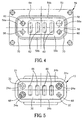
- adapter 14 includes a generally rectangular receptacle 56 projecting from flange 50 in a mating direction toward connector 12 as best seen in Figures 2, 3 and 4.
- the receptacle is defined by opposite minor sides 56a and opposite major sides 56b. In other words, the minor sides are the short sides and the major sides are the long sides of the receptacle.
- the receptacle has a bottom or base wall 56c which includes a pair of alignment holes 58 for receiving alignment pins 32 of connector 12.
- a pair of internally threaded holes 60 receive externally threaded ends 34a of jack screws 34 to secure connector 12 mated to adapter 14.
- Four rectangular holes 62 are formed in a recessed area 64 of base wall 56c through which ferrules 40 of connector modules 14 project.
- Figure 5 shows mating plug portion 24 of fiber optic connector 12 (Fig. 1).
- the plug portion is mated within receptacle 56 (Fig. 4) of adapter 14.
- the mating plug portion is defined by opposite minor sides 24a and opposite major sides 24b, with the plug portion configured or dimensioned for mating within receptacle 56.
- minor sides 24a and major sides 24b of the plug portion correspond to minor sides 56a and major sides 56b, respectively, of receptacle 56.
- face 30 of the plug portion includes four rectangular holes 66 through which ferrules 28 (Fig. 1) project.
- Plug portion 24 of connector 12 includes flattened corners 68 as best seen in Figure 5.
- Receptacle 56 of adapter 14 includes flattened corners 70 as best seen in Figure 4. These flattened corners of the plug portion and the receptacle provide a polarizing means so that connector 12 can be inserted into adapter 16 in only a preferred orientation.
- the invention is embodied in an EMI gasket, generally designated 72, which surrounds mating plug portion 24 of connector 12. Therefore, when the plug portion is inserted into receptacle 56 of adapter 14, the EMI gasket is disposed between the plug portion and the receptacle to prevent EMI leakage at the mating interface of the connector assembly.
- Figures 6-9 show the steps in fabricating EMI gasket 72 into its unique configuration.
- a flat gasket blank 74 is stamped in a wave-like or sinuous elongated strip from conductive sheet metal material, such as a copper alloy having somewhat springy or resilient characteristics.
- Figure 7 shows that gasket blank 74 then is formed into a bowed configuration in a direction transversely of the elongated strip. This transversely bowed configuration is best seen in Figure 8.
- Figure 9 shows EMI gasket 72 formed into its final, generally bow-tie configuration.
- the gasket is formed to include opposite minor sides 72a and opposite major sides 72b, with the major sides of the gasket being bowed inwardly in an unstressed condition.
- Minor sides 72a correspond to minor sides 24a (Fig. 5) of mating plug portion 24, and major sides 72b correspond to major sides 24b of the plug portion.
- major sides 72b of the gasket are spring biased against major sides 24b of the plug portion. This prevents the sides of the gasket from bowing outwardly of the plug portion and interfering with mating of connector 12 within adapter 16.
- rectangular gaskets tend to bow outwardly and, in fact, can be deformed during mating of connecting devices. The invention solves this problem.
Landscapes
- Physics & Mathematics (AREA)
- General Physics & Mathematics (AREA)
- Optics & Photonics (AREA)
- Details Of Connecting Devices For Male And Female Coupling (AREA)
- Mechanical Coupling Of Light Guides (AREA)
- Shielding Devices Or Components To Electric Or Magnetic Fields (AREA)
Abstract
Description
Claims (4)
- A connector assembly (10), comprising:a connector body (22) including a mating plug portion (24) for insertion into a receptacle (56) of a complementary mating connecting device (16), the mating plug portion being generally rectangular to define opposite minor sides (24a) and opposite major sides (24b) thereof; andan EMI gasket (72) about the rectangular mating plug portion (24) of said connector body, the EMI gasket being stamped of conductive sheet spring metal material and being rectangular to define opposite minor sides (72a) and opposite major sides (72b) thereof corresponding to the minor and major sides, respectively, of the mating plug portion, the EMI gasket (72) in an unstressed condition having a generally bow-tie configuration with the major sides (72b) thereof bowed inwardly whereby the major sides of the gasket are spring biased against the major sides (24b) of the plug portion (24) when the gasket (72) is installed on the plug portion.
- The connector assembly of claim 1 wherein said EMI gasket (72) is stamped with a sinuous configuration circumferentially about the gasket.
- An EMI gasket (72) for installing about a rectangular mating plug portion (24) of a connector (12) defined by opposite minor sides (24a) and opposite major sides (24b), the EMI gasket being rectangular to define opposite minor sides (72a) and opposite major sides (72b) thereof corresponding to the minor and major sides, respectively, of the mating plug portion, the EMI being stamped of conductive sheet spring metal material, and the EMI gasket (72) in an unstressed condition having a generally bow-tie configuration with the major sides (72b) thereof bowed inwardly whereby the major sides of the gasket are spring biased against the major sides (24b) of the plug portion (24) when the gasket is installed on the plug portion.
- The EMI gasket of claim 3 wherein the gasket (72) is stamped with a sinuous configuration circumferentially about the gasket.
Applications Claiming Priority (2)
| Application Number | Priority Date | Filing Date | Title |
|---|---|---|---|
| US09/614,758 US6305961B1 (en) | 2000-07-12 | 2000-07-12 | EMI gasket for connector assemblies |
| US614758 | 2000-07-12 |
Publications (3)
| Publication Number | Publication Date |
|---|---|
| EP1174959A2 true EP1174959A2 (en) | 2002-01-23 |
| EP1174959A3 EP1174959A3 (en) | 2003-02-05 |
| EP1174959B1 EP1174959B1 (en) | 2004-10-13 |
Family
ID=24462585
Family Applications (1)
| Application Number | Title | Priority Date | Filing Date |
|---|---|---|---|
| EP01116581A Expired - Lifetime EP1174959B1 (en) | 2000-07-12 | 2001-07-09 | EMI gasket for connector assemblies |
Country Status (7)
| Country | Link |
|---|---|
| US (1) | US6305961B1 (en) |
| EP (1) | EP1174959B1 (en) |
| JP (1) | JP3562500B2 (en) |
| KR (1) | KR100395392B1 (en) |
| CN (1) | CN1211894C (en) |
| DE (1) | DE60106343T2 (en) |
| TW (1) | TW523195U (en) |
Cited By (1)
| Publication number | Priority date | Publication date | Assignee | Title |
|---|---|---|---|---|
| WO2019113524A1 (en) | 2017-12-08 | 2019-06-13 | Smiths Interconnect Americas, Inc. | Highly configurable and modular high-speed connector system |
Families Citing this family (24)
| Publication number | Priority date | Publication date | Assignee | Title |
|---|---|---|---|---|
| US6572272B2 (en) * | 2000-11-29 | 2003-06-03 | Berg Technology, Inc. | Angled optical connector mounting assembly |
| US6442325B1 (en) * | 2001-10-17 | 2002-08-27 | Monster Cable Products, Inc. | XBOX optical adapter |
| EP1321785A3 (en) | 2001-12-14 | 2004-06-16 | Tyco Electronics Corporation | Emi shielded adapter for fiber optic connector systems |
| US6626706B2 (en) * | 2002-02-08 | 2003-09-30 | Microsoft Corporation | Eight-pin electrical connector and USB connector |
| US7029182B2 (en) * | 2002-03-01 | 2006-04-18 | Fci Americas Technology, Inc. | Angled optical connector adapter mounting assembly |
| US7121888B2 (en) * | 2002-07-10 | 2006-10-17 | 3M Innovative Properties Company | Multiple wire cable connector |
| JP4082694B2 (en) * | 2004-03-30 | 2008-04-30 | 日本航空電子工業株式会社 | EMI countermeasure connector |
| US7438596B2 (en) * | 2007-01-12 | 2008-10-21 | Tyco Electronics Corporation | Electrical connector assembly with EMI gasket |
| US7794156B2 (en) * | 2007-08-28 | 2010-09-14 | Emcore Corporation | Internal EMI washer for optical transceiver with parallel optic fiber ribbon |
| US8348516B2 (en) * | 2009-02-10 | 2013-01-08 | Amphenol Corporation | High density front panel optical interconnect |
| US8936484B2 (en) * | 2012-10-01 | 2015-01-20 | Hamilton Sundstrand Corporation | High voltage connector interfaces |
| TWI571021B (en) | 2013-12-10 | 2017-02-11 | 聯發科技股份有限公司 | High speed transmission connector |
| CN104836077A (en) * | 2013-12-10 | 2015-08-12 | 联发科技股份有限公司 | High-speed transmission connector |
| US9543710B2 (en) * | 2014-08-25 | 2017-01-10 | Tyco Electronics Corporation | Connector module with cable exit region gasket |
| US9658409B2 (en) | 2015-03-03 | 2017-05-23 | Senko Advanced Components, Inc. | Optical fiber connector with changeable polarity |
| KR101707143B1 (en) | 2015-09-23 | 2017-02-15 | 한국단자공업 주식회사 | PCB assembly having gasket and manufacturing method thereof |
| US10158194B2 (en) | 2016-01-15 | 2018-12-18 | Senko Advanced Components, Inc. | Narrow width adapters and connectors with spring loaded remote release |
| US9726830B1 (en) | 2016-06-28 | 2017-08-08 | Senko Advanced Components, Inc. | Connector and adapter system for two-fiber mechanical transfer type ferrule |
| US10228521B2 (en) | 2016-12-05 | 2019-03-12 | Senko Advanced Components, Inc. | Narrow width adapters and connectors with modular latching arm |
| US11822133B2 (en) | 2017-07-14 | 2023-11-21 | Senko Advanced Components, Inc. | Ultra-small form factor optical connector and adapter |
| US10281668B2 (en) | 2017-07-14 | 2019-05-07 | Senko Advanced Components, Inc. | Ultra-small form factor optical connectors |
| US12001064B2 (en) | 2017-07-14 | 2024-06-04 | Senko Advanced Components, Inc. | Small form factor fiber optic connector with multi-purpose boot |
| US11579379B2 (en) | 2019-03-28 | 2023-02-14 | Senko Advanced Components, Inc. | Fiber optic adapter assembly |
| CN115407459A (en) * | 2021-05-27 | 2022-11-29 | 华为技术有限公司 | MT card holder, MT card holder assembling method and adapter assembly |
Family Cites Families (11)
| Publication number | Priority date | Publication date | Assignee | Title |
|---|---|---|---|---|
| US3505463A (en) * | 1968-04-08 | 1970-04-07 | Us Army | Radio frequency energy barrier material |
| GB1179975A (en) * | 1968-08-21 | 1970-02-04 | Belling & Lee Ltd | Devices for Establishing Electrical Contact Between Movable Conductive Members. |
| US4529257A (en) * | 1983-02-22 | 1985-07-16 | International-Telephone & Telegraph Corp. | Combined electrical shield and environmental seal for electrical connector |
| US4572921A (en) * | 1984-07-30 | 1986-02-25 | Instrument Specialties Co., Inc. | Electromagnetic shielding device |
| US4676575A (en) * | 1986-06-19 | 1987-06-30 | Amp Incorporated | Sealing member for bulkhead connector |
| US4921437A (en) * | 1989-03-29 | 1990-05-01 | Amp Incorporated | Sealed electrical connector assembly with terminal retainer |
| US4940420A (en) * | 1989-08-17 | 1990-07-10 | Ford Motor Company | Electrical connector with retained boot |
| US4975065A (en) * | 1989-09-26 | 1990-12-04 | Avantek, Inc. | Microwave circuit module connector |
| DE19518567C1 (en) * | 1995-05-20 | 1996-11-28 | Kostal Leopold Gmbh & Co Kg | Electrical connector part |
| US6166919A (en) * | 1997-12-16 | 2000-12-26 | Notrel Networks Corporation | Casing mountable filler module |
| US5964621A (en) * | 1998-06-25 | 1999-10-12 | The Whitaker Corporation | Connector assembly for multi-pocket header |
-
2000
- 2000-07-12 US US09/614,758 patent/US6305961B1/en not_active Expired - Fee Related
-
2001
- 2001-07-09 EP EP01116581A patent/EP1174959B1/en not_active Expired - Lifetime
- 2001-07-09 DE DE60106343T patent/DE60106343T2/en not_active Expired - Fee Related
- 2001-07-09 JP JP2001245772A patent/JP3562500B2/en not_active Expired - Fee Related
- 2001-07-11 TW TW090211652U patent/TW523195U/en not_active IP Right Cessation
- 2001-07-12 CN CNB011254599A patent/CN1211894C/en not_active Expired - Fee Related
- 2001-07-12 KR KR10-2001-0041785A patent/KR100395392B1/en not_active Expired - Fee Related
Cited By (4)
| Publication number | Priority date | Publication date | Assignee | Title |
|---|---|---|---|---|
| WO2019113524A1 (en) | 2017-12-08 | 2019-06-13 | Smiths Interconnect Americas, Inc. | Highly configurable and modular high-speed connector system |
| CN111512201A (en) * | 2017-12-08 | 2020-08-07 | 史密斯互连美洲公司 | Highly adaptable and modular high-speed connector system |
| EP3721275A4 (en) * | 2017-12-08 | 2021-11-17 | Smiths Interconnect Americas, Inc. | HIGH-SPEED MODULAR AND HIGHLY CONFIGURABLE CONNECTOR SYSTEM |
| US11973296B2 (en) | 2017-12-08 | 2024-04-30 | Smiths Interconnect Americas, Inc. | Highly configurable and modular high-speed connector system |
Also Published As
| Publication number | Publication date |
|---|---|
| CN1211894C (en) | 2005-07-20 |
| EP1174959A3 (en) | 2003-02-05 |
| DE60106343T2 (en) | 2005-11-17 |
| US6305961B1 (en) | 2001-10-23 |
| DE60106343D1 (en) | 2004-11-18 |
| KR100395392B1 (en) | 2003-08-21 |
| TW523195U (en) | 2003-03-01 |
| CN1333587A (en) | 2002-01-30 |
| JP3562500B2 (en) | 2004-09-08 |
| KR20020006482A (en) | 2002-01-19 |
| JP2002203644A (en) | 2002-07-19 |
| EP1174959B1 (en) | 2004-10-13 |
Similar Documents
| Publication | Publication Date | Title |
|---|---|---|
| US6305961B1 (en) | EMI gasket for connector assemblies | |
| EP1026784B1 (en) | Shielded electrical connector | |
| US6095862A (en) | Adapter frame assembly for electrical connectors | |
| US6315590B1 (en) | Floating panel mounted connector assembly | |
| KR100448951B1 (en) | Fiber optic connector module | |
| US6217364B1 (en) | Electrical connector assembly with guide pin latching system | |
| EP1221630B1 (en) | Connector assembly floating mount | |
| EP1139504B1 (en) | Floating connector assembly | |
| CN100389525C (en) | Modular jack assembly for inserting plugs with multiple lead wires | |
| EP1026786B1 (en) | Grounded electrical connector with tail aligner | |
| EP1063730A1 (en) | Circuit board mounted connector assembly and method of fabricating same | |
| EP1172673A2 (en) | Alignment system for fiber optic connectors | |
| US6715928B1 (en) | Connector panel mount system | |
| US6786775B1 (en) | Modular jack assembly | |
| US20240396256A1 (en) | Single-pair ethernet mount housing | |
| EP1045486B1 (en) | Panel mounted connector assembly | |
| WO2004112201A9 (en) | Modular jack assembly | |
| US20020164899A1 (en) | Connector device and connector | |
| EP1310812A2 (en) | Optical connector system | |
| US20010003689A1 (en) | Electrical connector with terminal retainer | |
| US11378757B1 (en) | Reduced size optical connector for modules and circuit packs | |
| EP1109262A2 (en) | Electrical connector with terminal retainer | |
| CN223693405U (en) | High-speed connector shell, high-speed connector and connector assembly | |
| JP2003222760A (en) | Optical connector module |
Legal Events
| Date | Code | Title | Description |
|---|---|---|---|
| PUAI | Public reference made under article 153(3) epc to a published international application that has entered the european phase |
Free format text: ORIGINAL CODE: 0009012 |
|
| AK | Designated contracting states |
Kind code of ref document: A2 Designated state(s): AT BE CH CY DE DK ES FI FR GB GR IE IT LI LU MC NL PT SE TR |
|
| AX | Request for extension of the european patent |
Free format text: AL;LT;LV;MK;RO;SI |
|
| PUAL | Search report despatched |
Free format text: ORIGINAL CODE: 0009013 |
|
| AK | Designated contracting states |
Designated state(s): AT BE CH CY DE DK ES FI FR GB GR IE IT LI LU MC NL PT SE TR |
|
| AX | Request for extension of the european patent |
Extension state: AL LT LV MK RO SI |
|
| 17P | Request for examination filed |
Effective date: 20030712 |
|
| AKX | Designation fees paid |
Designated state(s): DE FR GB IT |
|
| 17Q | First examination report despatched |
Effective date: 20030923 |
|
| GRAP | Despatch of communication of intention to grant a patent |
Free format text: ORIGINAL CODE: EPIDOSNIGR1 |
|
| GRAS | Grant fee paid |
Free format text: ORIGINAL CODE: EPIDOSNIGR3 |
|
| GRAA | (expected) grant |
Free format text: ORIGINAL CODE: 0009210 |
|
| AK | Designated contracting states |
Kind code of ref document: B1 Designated state(s): DE FR GB IT |
|
| REG | Reference to a national code |
Ref country code: GB Ref legal event code: FG4D |
|
| RIN1 | Information on inventor provided before grant (corrected) |
Inventor name: ERNST, SCOT A. Inventor name: SZILAGYI, DANIEL B. Inventor name: GROIS, IGOR |
|
| REG | Reference to a national code |
Ref country code: IE Ref legal event code: FG4D |
|
| REF | Corresponds to: |
Ref document number: 60106343 Country of ref document: DE Date of ref document: 20041118 Kind code of ref document: P |
|
| ET | Fr: translation filed | ||
| PLBE | No opposition filed within time limit |
Free format text: ORIGINAL CODE: 0009261 |
|
| STAA | Information on the status of an ep patent application or granted ep patent |
Free format text: STATUS: NO OPPOSITION FILED WITHIN TIME LIMIT |
|
| 26N | No opposition filed |
Effective date: 20050714 |
|
| PGFP | Annual fee paid to national office [announced via postgrant information from national office to epo] |
Ref country code: FR Payment date: 20080729 Year of fee payment: 8 Ref country code: IT Payment date: 20080724 Year of fee payment: 8 |
|
| PGFP | Annual fee paid to national office [announced via postgrant information from national office to epo] |
Ref country code: GB Payment date: 20080729 Year of fee payment: 8 |
|
| PGFP | Annual fee paid to national office [announced via postgrant information from national office to epo] |
Ref country code: DE Payment date: 20090729 Year of fee payment: 9 |
|
| GBPC | Gb: european patent ceased through non-payment of renewal fee |
Effective date: 20090709 |
|
| REG | Reference to a national code |
Ref country code: FR Ref legal event code: ST Effective date: 20100331 |
|
| PG25 | Lapsed in a contracting state [announced via postgrant information from national office to epo] |
Ref country code: FR Free format text: LAPSE BECAUSE OF NON-PAYMENT OF DUE FEES Effective date: 20090731 |
|
| PG25 | Lapsed in a contracting state [announced via postgrant information from national office to epo] |
Ref country code: GB Free format text: LAPSE BECAUSE OF NON-PAYMENT OF DUE FEES Effective date: 20090709 |
|
| PG25 | Lapsed in a contracting state [announced via postgrant information from national office to epo] |
Ref country code: IT Free format text: LAPSE BECAUSE OF NON-PAYMENT OF DUE FEES Effective date: 20090709 |
|
| PG25 | Lapsed in a contracting state [announced via postgrant information from national office to epo] |
Ref country code: DE Free format text: LAPSE BECAUSE OF NON-PAYMENT OF DUE FEES Effective date: 20110201 |
|
| REG | Reference to a national code |
Ref country code: DE Ref legal event code: R119 Ref document number: 60106343 Country of ref document: DE Effective date: 20110201 |